

BOSE PANARAY LT3202 III, PANARAY LT4402 III, PANARAY LT9402 III, PANARAY LT9702 III Service Manual
Page 1

Panaray® LT Model
3202® III, 4402® III, 9402
TM
III, 9702® III,
MB24 III and MB12 III Loudspeakers
©2006 Bose Corporation
Service Manual
Reference Number 275484-SM Rev . 03
Page 2

CONTENTS
Warranty Information ......................................................................................................................................2
Specifications ............................................................................................................................................... 3-4
Product Description .........................................................................................................................................5
Part List Notes..................................................................................................................................................5
Packing List, Panaray® LT 3202® III Loudspeaker .........................................................................................6
Figure 1. Panaray L T 3202 III Loudspeaker Packaging View............................................................................6
Packing List, Panaray LT 4402® III Loudspeaker........................................................................................... 7
Figure 2. Panaray L T 4402 III Loudspeaker Packaging View............................................................................7
Packing List, Panaray L T 9402TM III Loudspeaker ....................................................................................... 8
Figure 3. Panaray L T 9402 III Loudspeaker Packaging View............................................................................8
Packing List, Panaray LT 9702® III Loudspeaker........................................................................................... 9
Figure 4. Panaray L T 9702 III Loudspeaker Packaging View............................................................................9
Packing List, Panaray L T MB24 III Bass Loudspeaker................................................................................ 10
Figure 5. Panaray L T MB24 III Bass Loudspeaker Packaging View ...............................................................10
Packing List, Panaray L T MB12 III Bass Loudspeaker................................................................................ 11
Figure 6. Panaray L T MB12 III Bass Loudspeaker Packaging View ............................................................... 11
Main Part List, Panaray LT 3202® III Loudspeaker (see Figure 7).............................................................. 12
Figure 7. Panaray L T 3202 III Loudspeaker Exploded View............................................................................12
Main Part List, Panaray LT 4402® III Loudspeaker (see Figure 8).............................................................. 13
Figure 8. Panaray L T 4402 III Loudspeaker Exploded View............................................................................13
Main Part List, Panaray LT 9402TM III Loudspeaker (see Figure 9) ............................................................ 14
Figure 9. Panaray L T 9402TM III Loudspeaker Exploded View.......................................................................14
Main Part List, Panaray LT 9702® III Loudspeaker (see Figure 10) ............................................................ 15
Figure 10. Panaray L T 9702 III Loudspeaker Exploded View.......................................................................... 15
Main Part List, Panaray L T MB24 III Bass Loudspeaker ............................................................................. 16
Figure 1 1. Panaray L T MB24 III Bass Loudspeaker Exploded View ............................................................... 16
Main Part List, Panaray L T MB12 III Bass Loudspeaker ............................................................................. 17
Figure 12. Panaray L T MB12 III Bass Loudspeaker Exploded View ...............................................................17
Disassembly Procedures .......................................................................................................................... 18-20
T est Procedures ........................................................................................................................................ 21-22
Model 4402, 9402, 9702, MB24 and MB12 Series III Speaker Test Cable................................................... 21
Model 3202 III Speaker Test Cable............................................................................................................... 21
Loudspeaker Wiring Diagrams................................................................................................................ 22-24
Accessories Used With the Panaray L T Series III Loudspeakers............................................................... 24
High Frequency Compression Driver Diaphragm Replacement Procedure ............................................. 25
Service Manual Revision History ................................................................................................................. 26
CAUTION: The Bose® Panaray LT Loudspeakers
contain no user-serviceable parts. To prevent warranty infractions,
refer servicing to warranty service stations or factory service.
WARRANTY INFORMATION
The Bose Panaray L T Model 3202, 4402, 9402, 9702, MB24 and MB12 Series III
Loudspeakers are covered by a 5-year transferable limited warranty .
PROPRIET ARY INFORMATION
THIS DOCUMENT CONT AINS PROPRIET ARY INFORMA TION OF
BOSE CORPORA TION WHICH IS BEING FURNISHED ONLY FOR
THE PURPOSE OF SERVICING THE IDENTIFIED BOSE PRODUCT
BY AN AUTHORIZED BOSE SERVICE CENTER OR OWNER OF
THE BOSE PRODUCT, AND SHALL NOT BE REPRODUCED OR
USED FOR ANY OTHER PURPOSE.
2
Page 3

MECHANICAL
SPECIFICATIONS
External dimensions, single speaker
System weight, unpackaged single speaker
System weight, packaged single speaker
®
9702
III: 42.2" H x 22.5" W x 18.0" D (1072 x 572 x 368 mm)
9402TM III: 34.6" H x 22.5" W x 23.7" D (879 x 572 x 604 mm)
4402® III: 34.0" H x 18.5" W x 24.0" D (884 x 471 x 610 mm)
3202® III: 42.2" H x 22.5" W x 35.9" D (1072 x 573 x 913 mm)
MB24 III: 28.1" H x 20.0" W x 25.5" D (712 x 508 x 647 mm)
MB12 III: 14.5" H x 20.0" W x 25.5" D (368x 508 x 647 mm)
9702 III: 95.5 lbs (43 kg)
9402 III: 1 13.0 lbs (51 kg)
4402 III: 1 11.1 lbs (50 kg)
3202 III: 194.0 lbs (88 kg)
MB24 III: 129.0 lbs (59 kg)
MB12 III: 65.0 lbs (29.5 kg)
9702 III: 123.5 lbs (56 kg)
9402 III: 145.5 lbs (66 kg)
4402 III: 141.1 lbs (64 kg)
3202 III: 240.7 lbs (109 kg)
MB24 III: 147.0 lbs (67 kg)
MB12 III: 74 lbs (34 kg)
ELECTRICAL
Driver Complement
9702 III: Mid Freq: two V2 drivers
High Freq: one 1.4" compression driver
9402 III: Mid Freq: two V2 drivers
High Freq: one 1.4" compression driver
4402 III: Mid Freq: two V2 drivers
High Freq: one 1.4" compression driver
3202 III: Mid Freq: four V2 drivers
High Freq: one 1.4" compression driver
MB24 III: Two 12" low frequency drivers
MB12 III: One 12" low frequency driver
Sensitivity (dB SPL, 1Watt at 1 meter)
9702 III: Mid 105, High 104, Passive 104
9402 III: Mid 106, High 106, Passive 106
4402 III: Mid 106, High 107, Passive 108
3202 III: Mid 1 1 1, High 107, Passive 110
MB24 III: Parallel Mode 94, Discrete Mode 91 (per driver)
MB12 III: Discrete Mode 91
3
Page 4

SPECIFICATIONS
ELECTRICAL (Continued)
Maximum sound pressure level (dB SPL) - pink noise per IEC 268-5
9702 III: Mid 127, High 123, Passive 126
9402 III: Mid 128, High 125, Passive 128
4402 III: Mid 126, High 128, Passive 130
3202 III: Mid 132, High 130, Passive 135
MB24 III: Parallel Mode 123, Discrete Mode 123
MB12 III: Discrete Mode 1 17
Frequency Range
Loudspeaker Impedance
Maximum Power Handling, Watt s
®
9702
III: 180Hz - 16kHz (+ 3dB)
9402TM III: 180Hz - 16kHz (+ 3dB)
4402® III: 180Hz - 16kHz (+ 3dB)
3202® III: 200Hz - 16kHz (+ 3dB)
MB24 III: 40Hz - 250Hz (+ 3dB)
MB12 III: 40Hz - 250Hz (+ 3dB)
Compression Driver: 8 Ohms
Vee-Two: 2 Vee-Two's are wired in series for 8 Ohms
MB24 III Bass Drivers: 8 Ohms each
MB12 III Bass Driver: 8 Ohms
9702 III: Bi-amped: Mid 140, High 75 Passive: 140
9402 III: Bi-amped: Mid 140, High 75 Passive: 140
4402 III: Bi-amped: Mid 140, High 75 Passive: 140
3202 III: Bi-amped: Mid 280, High 75 Passive: 280
Bi-amped / Dual Midrange: Mid1 140; Mid2 140; High 75
MB24 III: Parallel Mode 800, Discrete Mode 400 each driver
MB12 III: Discrete Mode 400
4
Page 5

PRODUCT DESCRIPTION
The Bose® Panaray® L T Series III Loudspeakers are designed to provide quality sound in venues where speaker-to-listener distance, room reverberation time, ambient noise and high SPL
requirements are key factors. Typical installations include performing arts facilities, theaters,
auditoriums, houses of worship, stadiums and arenas.
The Panaray LT Series III loudspeakers are a direct replacement for the Panaray LT Series II
loudspeaker in indoor spaces. The Panaray LT Series III loudspeaker does not meet the requirements for permanent outdoor installation.
The Panaray LT Series III loudspeakers utilize a high frequency compression driver and two or
more V2 assemblies for midrange. The MB24 bass module contains two 12 inch bass drivers.
The MB12 bass module contains one 12 bass driver .
The Panaray LT Series III loudspeakers come standard with a perforated metal grille and are
available in both black and white versions.
PART LIST NOTES
1. This part is not normally available from Customer Service. Approval from the Field Service
Manager is required before ordering.
2. The individual parts located on the PCBs are listed in the Electrical Part List.
3. This part is critical for safety purposes. Failure to use a substitute replacement with the
same safety characteristics as the recommended replacement part might create shock, fire
and/or other hazards.
4. This part is referenced for informational purposes only. It is not stocked as a repair part.
Refer to the next higher assembly for a replacement part.
5
Page 6

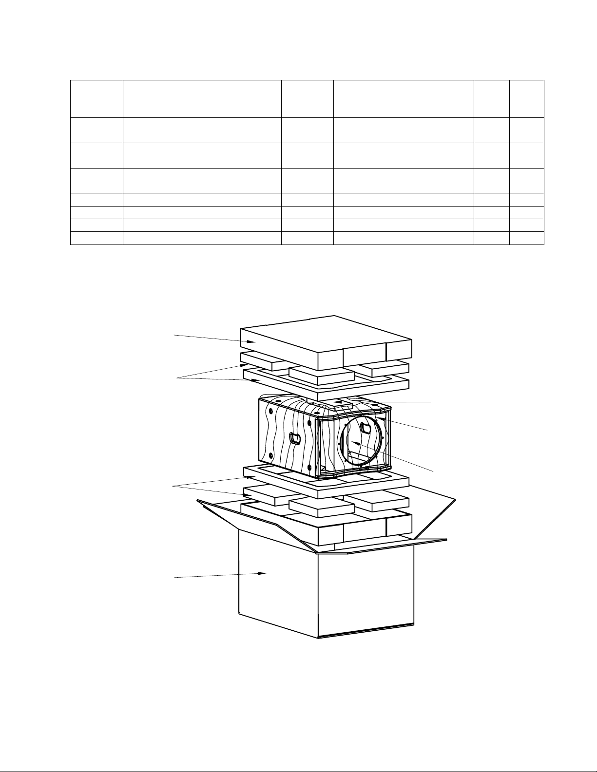
PACKING LIST
Item
Description Bose®
Vendor Part Number Qty Note
Panaray® LT 3202® III Loudspeaker
Number
Number
1 PP Cover 2 Triangle Paper 3 PP Foam Middle 4 Triangle Paper 5 Carton 6
7 PE Bag, 1850x1430x0.3 -
- Owner's Guide, Models 3202,
Kit, Carton, Model 3202 III,
includes:
Loudspeaker, Model 3202 III
(not included with carton kit)
4402, 9402 and 9702 III
276855
275484
276859
Part
- 1
LT3202-III-5-104
LT3202-III-5-102
LT3202-III-5-106
LT3202-III-5-101
LT3202-III-5-107
LT3202 III
LT3202-III-5-104
LT9702-III-5-108
2 4
2 4
1 4
2 4
1 4
1 4
1 4
1
Figure 1. Panaray LT 3202 III Loudspeaker Packaging View
6
Page 7

PACKING LIST
Item
Description Bose®
Vendor Part Number Qty Note
Panaray® LT 4402® III Loudspeaker
Number
Number
1 PP Cover 2 Triangle Paper 3 PP Foam Middle 4 Triangle Paper 5 Carton 6
7 PE Bag, 1850x1430x0.3 -
- Owner's Guide, Models 3202,
Kit, Carton, Model 4402 III,
includes:
Loudspeaker, Model 4402 III
(not included with carton kit)
4402, 9402 and 9702 III
276856
275485
276859 - 1
Part
- 1
LT4402-III-5-103
LT4402-III-5-102
LT4402-III-5-106
LT4402-III-5-101
LT4402-III-5-107
LT4402 III
LT9702-III-5-108
2 4
2 4
1 4
2 4
1 4
1 4
1 4
Figure 2. Panaray LT 4402 III Loudspeaker Packaging View
7
Page 8

PACKING LIST
Item
Description Bose®
Vendor Part Number Qty Note
Panaray® LT 9402TM III Loudspeaker
Number
Number
1 PP Cover 2 Triangle Paper 3 PP Foam Middle 4 Carton 5
6 PE Bag, 1850x1430x0.3 -
- Owner's Guide, Models 3202,
Kit, Carton, Model 9402 III,
includes:
Loudspeaker, Model 9402 III
(not included with carton kit)
4402, 9402 and 9702 III
276857
263940
276859 - 1
Part
- 1
LT9402-III-5-105
LT9402-III-5-101
LT9402-III-5-106
LT9402-III-5-107
LT9402 III
LT9702-III-5-108
2 4
2 4
1 4
1 4
1 4
1 4
Figure 3. Panaray LT 9402 III Loudspeaker Packaging View
8
Page 9

PACKING LIST
Item
Description Bose®
Vendor Part Number Qty Note
Panaray® LT 9702® III Loudspeaker
Number
Number
1 PP Cover 2 Triangle Paper 3 PP Foam Middle 4 Carton 5
6 PE Bag, 1850x1430x0.3 -
- Owner's Guide, Models 3202,
Kit, Carton, Model 9702 III,
includes:
Loudspeaker, Model 9702 III
(not included with carton kit)
4402, 9402 and 9702 III
276858
275486
276859 - 1
Part
- 1
LT9702-III-5-104
LT9702-III-5-101
LT9702-III-5-105
LT9702-III-5-106
LT9702 III
LT9702-III-5-107
2 4
2 4
1 4
1 4
1 4
1 4
Figure 4. Panaray LT 9702 III Loudspeaker Packaging View
9
Page 10

PACKING LIST
Item
Description Bose®
Vendor Part Number Qty Note
Panaray® LT MB24 III Bass Loudspeaker
Number
Kit, Carton, Model MB24 III,
includes:
1 PE Bag, 1600 x 1160 x 0.1mm - LTMB24-III-2-104 1 4
2 PE Bag, 240 x 350 x 0.1mm - LT9702-III-5-102 1 4
3 PP Foam, 672 x 790 x 150mm - LTMB24-III-2-103 2
4 PP Foam, Middle,
804 x 686 x 80mm
5 Paper Cover,
808 x 676 x 157mm
6 Triangle Paper,
790 x 236 x 80mm
7 Carton, MB24 - LTMB24-III-2-101 1
- Manual, Users 278247 - 1
Part
Number
-
- LTMB24-III-2-106 1
- LTMB24-III-2-105 2
- LTMB24-III-2-102 4
- 1
1
5
6
4
6
5
7
2
6
4
6
3
Figure 5. Panaray LT MB24 III Bass Loudspeaker Packaging View
10
Page 11
PACKING LIST
Item
Description Bose®
Vendor Part Number Qty Note
Panaray® LT MB12 III Bass Loudspeaker
Number
Kit, Carton, Model MB24 III,
includes:
1 Paper Cover,
774x636x107mm
2 Cushioning Material,
770x632x100mm
3 Manual, Users 278247 BOSE/LT_MB12 1
4 PE Bag, 1200x1260x0.04mm - BS1000 1 4
5
6 Carton, MB12 309574 LTMB12-III-2-101 1
LT MB12 III Loudspeaker
Part
Number
-
- LTMB12-III-2-103 1
- LTMB12-III-2-102 2
REF - 1
- 1
1
2
2
6
3
4
5
Figure 6. Panaray LT MB12 III Bass Loudspeaker Packaging View
11
Page 12

MAIN PART LIST
Part Number Item
Description
Qty Note
Panaray® LT 3202® III Loudspeaker (see Figure 7)
Number
1 Logo, Panaray LT - - 1 4
2 Kit, Grille Screw, TA4x15 (14 screws per kit) 297502 297503 1
3 Cap, Spring - - 1 4
4 Spring, Logo - - 1 4
5 Clip, Retaining, Logo - - 1 4
6 Grille Assembly, include s screws, tape, logo,
fastener and spring
7 Gasket, Grille, consists of 3 sect ions 274622 274622 1 4
8 Gasket, Compression Driver 263911 263911 1 4
9 Disk, Align, Compression Driver 263912 263912 1 4
10 Screw, KM4x12 - - 10 4
11 Screw, KM6x12 - - 4 4
12 Plate, Mount, Compressio n Driver 276849 276849 1 4
13 Screw, TM6x30 - - 20 4
14 Compression Driver, 1.4” 276860 276860 1
15 Gasket, Rear Panel 298558 298558 1 4
16 Panel, Rear 273489 273489 1 4
17 Screw, TM4x15 - - 12 4
18 VEE Two Assembly (includes drivers) 298172 298559 4
19 Input Panel with Cros sover PCB 297510 298560 1
- Gasket, Input Panel 274628 274628 2 4
- Compression Driver Replaceme nt Di aphragm 276861 276861 1
- Logo Kit with tape, fastener and spring 297504 297505 1
- Screw, Hang Point, 3/8” x 16 2985 91 299316 16
Black White
298171 298556 1
2
1
2
3
4
5
6
7
8 9 10 11 12 13 14 15 16
19
17
18
Figure 7. Panaray
®
LT 3202® III Loudspeaker Exploded View
12
Page 13

MAIN PART LIST
Part Number Item
Description
Qty Note
Panaray® LT 4402® III Loudspeaker (see Figure 8)
Number
1 Grille Assembly, includes:
screws, tape, logo, fastener and spring
2 Gasket, Grille (consists of three sections) - - 1 4
3 Kit, Grille Screw, TA4x15 (14 screws per kit) 297502 297503 1
4 Gasket, Compression Driver 263911 263911 1 4
5 Disk, Alignment, Compression Driver 263912 263912 1 4
6 Screw, KM4x12 - - 4 4
7 Screw, KM6x12 - - 4 4
8 Plate, Mount, Compression Driver 276849 276849 1
9 Screw, TM6x30 - - 14 4
10 Compression Driver 276860 276860 1
11 Gasket, Panel, 9702 263909 263909 1 4
12 Panel, Rear 263908 - 1 4
13 Screw, TM4x15 - - 12 4
14 VEE Two Assembly (includes drivers) 298172 298559 2
15 Input Panel with Crossover PCB 297523 298583 1
16 Screw, KM3x12 - - 4 4
17 Gasket, Input Panel 263920 263920 2 4
- Compression Driver Replacement Diaphragm 276861 276861 1
- Logo Kit with tape, fastener and spring 297504 297505 1
- Screw, Hang Point, 3/8” x 16 298591 299316 16
Black White
297521 298580 1
9
6
5
4
3
2
1
8
7
10
11
12
13
Figure 8. Panaray
9
®
LT 4402® III Loudspeaker Exploded View
17
16
15
14
13
Page 14

MAIN PART LIST
Part Number Item
Description
Qty Note
Panaray® LT 9402TM III Loudspeaker (see Figure 9)
Number
1 Kit, Grille Screw, TA4x15 (14 screws per kit) 297502 297503 10
2 Logo, Panaray LT - - 1 4
3 Grille Assembly (includes screws, tape, logo,
fastener and spring)
4 Cap, Spring - - 1 4
5 Spring, Logo - - 1 4
6 Clip, Retaining, Logo - - 1 4
7 Gasket, Grille
(consists of three sections)
8 Gasket, Compression Driver 263911 263911 1 4
9 Disk, Alignment, Comp Driver 263912 263912 1 4
10 Screw, KM4x12 - - 4 4
11 Screw, KM6x12 - - 4 4
12 Plate, Mount, Compression Driver 276849 276849 1
13 Screw, TM6x30 - - 14 4
14 Compression Driver 276860 276860 1
15 Gasket, Panel 263909 263909 1 4
16 Panel, Rear 263908 - 1 4
17 Screw, TM4x15 - - 12 4
18 VEE Two Assembly (includes drivers) 298172 298559 2
19 Panel, Input, with Crossover 297526 298585 1
- Compression Driver Replacement Diaphragm 276861 276861 1
- Logo Kit (includes tape, fastener and spring) 297504 297505 1
- Screw, Hang Point, 3/8” x 16 298591 299316 16
Black White
297525 298584 1
- - 1 4
1
2
3
4
5
6
7
1
8 9 10 11 12 13 14 15 16
19
Figure 9. Panaray® LT 9402TM III Loudspeaker Exploded View
17
18
14
Page 15

MAIN PART LIST
Part Number Item
Description
Qty Note
Panaray® LT 9702® III Loudspeaker (see Figure 10)
Number
1 Grille Assembly (includes: screws, tape, logo,
fastener and spring)
2 Kit, Grille Screw, TA4x15(14 screws per kit) 297502 297503 1
3 Clip, Retaining, Logo - - 1 4
4 Spring, Logo - - 1 4
5 Cap, Spring - - 1 4
6 Logo, Panaray LT - - 1 4
7 Gasket, Grille (consists of three sections) - - 1 4
8 Gasket, Compression Driver 263911 263911 1 4
9 Disk, Alignment, Comp Driver 263912 263912 1 4
10 Screw, KM4x12 - - 4 4
11 Screw, KM6x12 - - 4 4
12 Plate, Mount, Compression Driver 276849 276849 1
13 Screw, TM6x30 - - 14 4
14 Compression Driver 276860 276860 1
15 Gasket, Panel, 9702 263909 263909 1 4
16 Panel, Rear 263908 - 1 4
17 Screw, TM4x15 - - 12 4
18 VEE Two Assembly (includes drivers) 298172 298559 2
19 Panel, Input, with Crossover 297528 298587 1
- Compression Driver Replacement Diaphragm 276861 276861 1
- Logo Kit (includes tape, fastener and spring) 297504 297505 1
- Screw, Hang Point, 3/8” x 16 298591 299316 16
Black White
297527 298586 1
91011
8
7
6
5
4
3
2
1
12 13 14 15
19
16
17
18
Figure 10. Panaray® LT 9702® III Loudspeaker Exploded View
15
Page 16

MAIN PART LIST
Part Number Item
Description
Qty Note
Panaray® LT MB24 III Bass Loudspeaker
Number
1 Gasket, Grille, MB24 Bass Module - - 1 4
2 Grille Assembly, includes screws, logo, tape,
fastener and spring
3 Logo Kit, includes tape, fastener and spring 276848 297505 1
4 Grille Screw Kit (14 screws) 297502 291904 1
5 Gasket, Woofer - - 2 4
6 Gasket, Input Panel - - 1 4
7 Input Panel Kit 297518 298570 1
8 Woofer Assembly, 12 inch, TBX 297519 297519 2
9 Screw, Woofer - - 16 4
Black White
297514 298561 1
9
8
1
2
3
6
4
5
7
Figure 11. Panaray LT MB24 III Bass Loudspeaker Exploded View
16
Page 17

MAIN PART LIST
Part Number Item
Description
Qty Note
Panaray® LT MB12 III Bass Loudspeaker
Number
1 Gasket, Grille, MB12 Bass Module - - 1 4
2 Grille Screw Kit (14 screws) 297502 297503 1
3 Grille Assembly, (includes screws and logo) 296721 298588 1
4 Logo Kit, includes tape, fastener and spring 297504 297505 1
5 Screw, Woofer - - 8 4
6 Woofer Assembly, 12 inch, TBX 297519 297519 1
7 Gasket, Woofer - - 1 4
8 Gasket, Input Panel - - 1 4
9 Input Panel Kit 297518 298589 1
Black White
4
3
2
6
5
7
1
8, 9
Figure 12. Panaray LT MB12
III Bass Loudspeaker Exploded View
17
Page 18

DISASSEMBLY PROCEDURES
CAUTION: The rear of the Panaray® LT
loudspeakers can become extremely hot
during normal use. Do not attempt to service
the loudspeakers until they have cooled to
room temperature.
Model 3202® III Loudspeaker
Note: Refer to Figure 7 for the following
procedures.
1. Grille Removal
1.1 Remove the fourteen screws (2) that
secure the grille assembly (6) to the cabinet.
1.2 Lift the grille assembly off of the cabinet.
Retain the grille gasket (7) for re-use.
2. Logo Removal
2.1 Remove the grille using procedure 1
above.
2.2 On the back of the grille, carefully remove the slotted washer that retains the
spring and spacer against the back of the
grille. Note the direction the spacer faces.
Slide the spring and spacer off of the logo
post.
4. VEE T wo Assembly Removal
4.1 Remove the four screws that secure the
assembly to the cabinet. These screws are
located at the four corners of the VEE Two
assembly. Do not remove the other screws
around the casting. Carefully lift the assembly out of the cabinet. Make a note of the
wiring configuration, and disconnect the two
wires from the connector.
5. Input Panel Assembly Removal
5.1 Remove the four screws that secure the
input panel assembly to the cabinet. Disconnect the cables that plug into the PCB. Lift
out the assembly.
Model 4402
Note: Refer to Figure 8 for the following
procedures.
1. Grille Removal
1.1 Remove the fourteen screws (3) that
secure the sides of the grille assembly (1) to
the cabinet. Remove the six screws (3) that
secure the grille assembly to the front of the
cabinet.
®
III Loudspeaker
3. Compression Driver Removal
3.1 Remove the twelve screws (18) that
secure the rear panel (16) to the cabinet. Lift
off the rear panel. Retain the gasket (15) for
re-use.
3.2 Remove the four screws (13) that secure
the Compression Driver Mounting Plate (12)
to the cabinet. Lift the compression driver
(14) out of the cabinet. Make a note of the
wiring configuration, and disconnect the
wires from the compression driver.
3.3 Remove the four screws (11) that secure
the compression driver to the mounting plate.
Lift off the driver .
1.2 Lift the grille assembly off of the cabinet.
The gasket should remain adhered to the
cabinet.
2. Logo Removal
2.1 Remove the grille using procedure 1
above.
2.2 On the back of the grille, carefully remove the slotted washer that retains the
spring and spacer against the back of the
grille. Note the direction the spacer faces.
Slide the spring and spacer off of the logo
post.
2.3 Lift the logo off of the grille.
18
Page 19

DISASSEMBLY PROCEDURES
3. Compression Driver Removal
3.1 Remove the twelve screws (13) that
secure the rear panel (12) to the cabinet. Lift
off the rear panel. The gasket should remain
adhered to the cabinet.
3.2 Make a note of the wiring configuration,
and disconnect the wires from the compression driver. Remove the four screws (9) that
secure the Compression Driver Mounting
Plate (8) to the cabinet. Lift the compression
driver (10) out of the cabinet.
4. VEE T wo Assembly Removal
4.1 Remove the four screws that secure the
assembly to the cabinet. These screws are
located at the four corners of the VEE Two
assembly. Do not remove the other screws
around the casting. Carefully lift the assembly out of the cabinet. Make a note of the
wiring configuration, and disconnect the two
wires from the connector.
5. Input Panel Assembly Removal
5.1 Remove the four screws that secure the
input panel assembly to the cabinet. Lift the
assembly away from the cabinet. Be careful
not to damage any wires.
Model 9402TM III Loudspeaker
Note: Refer to Figure 9 for the following
procedures.
1. Grille Removal
2. Logo Removal
2.1 Remove the grille using procedure 1
above.
2.2 On the back of the grille, carefully remove the slotted washer that retains the
spring and spacer against the back of the
grille. Note the direction the spacer faces.
Slide the spring and spacer off of the logo
post.
2.3 Lift the logo off of the grille.
3. Compression Driver Removal
3.1 Remove the twelve screws (17) that
secure the rear panel (16) to the cabinet.
Lift off the rear panel. The gasket should
remain adhered to the cabinet.
3.2 Make a note of the wiring configuration,
and disconnect the wires from the compression driver. Remove the four screws (13)
that secure the Compression Driver Mounting Plate (12) to the cabinet. Lift the compression driver (14) out of the cabinet.
4. VEE T wo Assembly Removal
4.1 Remove the four screws that secure the
assembly to the cabinet. These screws are
located at the four corners of the VEE Two
assembly. Do not remove the other screws
around the casting. Carefully lift the assembly out of the cabinet. Make a note of the
wiring configuration, and disconnect the two
wires from the connector.
1.1 Remove the fourteen screws (1) that
secure the grille assembly (3) to the cabinet.
1.2 Lift the grille assembly off of the cabinet.
The gasket should remain adhered to the
cabinet.
5. Input Panel Assembly Removal
5.1 Remove the four screws that secure the
input panel assembly to the cabinet. Lift the
assembly away from the cabinet. Be careful
not to damage any wires.
19
Page 20

DISASSEMBLY PROCEDURES
Model 9702® III Loudspeaker
Note: Refer to Figure 10 for the following
procedures.
1. Grille Removal
1.1 Remove the fourteen screws (2) that
secure the grille assembly (1) to the cabinet.
1.2 Lift the grille assembly off of the cabinet.
The gasket should remain adhered to the
cabinet.
2. Logo Removal
2.1 Remove the grille using procedure 1
above.
2.2 On the back of the grille, carefully remove the slotted washer that retains the
spring and spacer against the back of the
grille. Note the direction the spacer faces.
Slide the spring and spacer off of the logo
post.
2. Place the VEE T wo assembly on a flat
surface so that the aluminum casting with
the Bose logo is facing upward.
3. Using a Phillips-head screwdriver, remove
all of the screws around the perimeter of the
casting. Carefully lift off the casting. The
drivers will be exposed.
4. Make a note of the wiring configuration,
and cut the wires as close to the terminals
as possible.
5. Remove the three screws that secure the
driver into the housing. Lift it out of the
housing.
Re-assembly note: When installing the
new driver, ensure that the gasket for the
driver and the gasket for the aluminum
casting are correctly positioned to provide
an airtight seal after re-assembly.
Model MB24 and MB12 III Bass Loudspeakers
2.3 Lift the logo off of the grille.
3. VEE T wo Assembly Removal
3.1 Remove the four screws that secure the
assembly to the cabinet. These screws are
located at the four corners of the VEE Two
assembly. Do not remove the other screws
around the casting. Carefully lift the assembly out of the cabinet. Make a note of the
wiring configuration, and disconnect the two
wires from the connector.
4. Input Panel Assembly Removal
4.1 Remove the four screws that secure the
input panel assembly to the cabinet. Disconnect the cables that plug into the PCB. Lift
out the assembly.
VEE Two Driver Removal Procedure
1. Remove the VEE Two assembly using the
appropriate disassembly procedures for the
speaker under repair .
Refer to Figure 1 1 or 12, as appropriate,
for the following procedures.
1. Grille Removal
1.1 Using a Phillips-head screwdriver , re-
move the screws that secure the grille to the
enclosure. Lift off the grille.
2. Driver Removal
2.1 Perform procedure 1 above.
2.2 Using a Phillips-head screwdriver , re-
move the 8 screws that secure the driver to
the enclosure.
2.3 Lift the driver out of the enclosure. Make
a note of the wiring configuration and cut the
wires as close to the terminals as possible.
Re-assembly Note: Be sure that the driver
gasket is properly aligned to provide an
airtight seal. If the gasket is damaged, use a
new one.
20
Page 21

TEST PROCEDURES
3. Input Panel Removal
3.1 Using a Phillips-head screwdriver , re-
move the 8 screws that secure the input
panel to the enclosure. Lift the input panel
out of the enclosure.
Test Cables for Model 3202®, 4402®,
TM
9402
, 9702® and MB24 III Loudspeakers
You will need to make up a test cable in order
to be able to perform the tests below .
Parts Needed:
1 - Neutrik Speakon NL4FX 4-pole connector
(4402, 9402 and 9702 speakers)
1 - Neutrik Speakon NL8 8-pole connector
(3202 speaker)
1 - Dual banana jack
6 feet of 16-18 AWG twisted pair wire
®
Panaray
LT Model 3202®, 4402®, 9402
and 9702® Series III Loudspeakers
Note: Ensure that the speaker under test
is in P ASSIVE mode for the following test s.
To check the mode the speaker is set up to
operate in, you will need to remove the four
screws that secure the input panel assembly
in place and verify that the jumpered connector plugged into the crossover PCB is in the
P ASSIVE jack. Refer to the disassembly
procedures in this service manual for instructions on how to remove the input panel.
1. Rub and Tick Test
1.1 Apply an 8 V rms, 10 Hz signal to the
input terminals of the speaker.
1.2 No extraneous noise such as rubbing,
scraping or ticking should be heard.
TM
Connect one lead of the twisted pair wire to
the positive tab of the dual banana jack.
Connect the other lead to the GND tab of the
dual banana jack.
Connect the positive lead of the wire to
the 1+ position of the Neutrik connector.
Connect the negative lead of the wire to the
1- position of the Neutrik connector. Refer
to the appropriate drawing for the speaker
below.
16-18AWG
2+
2-
1-
Neutrik Speakon
1+
4 pole connector
(back shown)
twisted pair wire
GND
Dual banana jack
Model 4402, 9402, 9702, MB24 and MB12
Series III Speaker Test Cable
Neutrik Speakon
Dual banana jack
GND
8 pole connector
(back shown)
16-18AWG
twisted pair wire
4+
4-
1+
1-
2+
2. Phase Test
2.1 Disconnect the connectors at the VEE-2
terminals. Momentarily apply 8 Vdc + 1 Vdc
to the terminals, observing polarity when
connecting the DC power supply. Both of the
drivers should move outward when the DC
level is applied.
3. Frequency Power Sweep Test
3.1 Apply an 8 V rms, 10 Hz signal to the
speaker input terminals.
3.2 Sweep the input frequency from 10 Hz
to 2 kHz.
3.3 Lower the applied input to 4 Vrms, and
sweep the input frequency from 2 kHz to 5
kHz.
3.4 Listen for any buzzes, rattles or other
3-
3+
2-
extraneous noises from the loudspeaker.
Model 3202 III Speaker Test Cable
21
Page 22

TEST PROCEDURES
Model MB24 and MB12 Series III Bass
Loudspeakers
Note: For the MB24, ensure that the speaker
under test is in P ARALLEL mode for the
following tests. To check the mode the
speaker is set up to operate in, you will need
to remove the eight screws that secure the
input panel assembly in place and verify that
the jumpered connector plugged into the
crossover PCB is in the PARALLEL jack.
Refer to the disassembly procedures in this
service manual for instructions on how to
remove the input panel. This does not apply
to the MB12, as it has only one woofer.
1. Rub and Tick Test
1.1 Apply a 10 V rms, 10 Hz signal to the
input terminals of the speaker.
1.2 No extraneous noise such as rubbing,
scraping or ticking should be heard.
2. Phase Test
2.1 Disconnect the connectors at the driver
terminals. Momentarily apply 10 Vdc + 1 Vdc
to the terminals, observing polarity when
connecting the DC power supply. Both of the
drivers should move outward when the DC
level is applied.
3. Frequency Power Sweep Test
3.1 Apply a 10 V rms, 10 Hz signal to the
speaker input terminals.
3.2 Sweep the input frequency from 10 Hz
to 250 Hz.
3.3 Listen for any buzzes, rattles or other
extraneous noises from the loudspeaker.
Loudspeaker Wiring Diagrams
1+
1-
4-
3-
4-
3-
3+ 2-
1+
3+ 2-
2+
1-
2+
1+
1-
EAG011-03 V1.1
2+
2-
3+
3-
4+
4-
4+
4+
CON1
Passive
CON2
Biamped
Biamped(Dual Mid Range)
Mid 1+
Mid 1-
Mid 2+
CON3
Mid 2-
To In+
To In-
V2
+
-
4.5'
+
-
4.5'
MID-FREQUENCY DRIVERS
V2
+
-
4.5'
+
-
4.5'
EAG011-02
C1
+
3UF/250V
IN
-
HIGH-FREQUENCY
DRIVER
C2
6UF/250V
L1
0.72mH/
1.3mm
OUT
4.5'
4.5'
4.5'
4.5'
HI+HI-
V2
+
-
+
-
V2
+
-
+
-
Connector
5556 2Î11P
HI
+
-
T1.4hp
Model 3202® Series III Wiring Diagram
22
Page 23

Loudspeaker Wiring Diagrams
+
IN
2-2+1+ 1-
2-
1+
2+
1-2-
1+
2+
1-
+
-
-
Discrete
Parallel
EAG013-01 1-01
+
-
+
-
Woofer1 Woofer2
8981 5.08mm4P
Connector
IN
C1
EAG011-01 V1.1
Biamped
C2
3UF/250V
2-2+ 1+ 1-
6UF/250V
L1
0.72mH/1.3mm
Connector
8981 5.08mm4P
Passive
OUT
HI+HI-
HI
+
T1.4hp
-
HIGH-FREQUENCY
DRIVER
MID-FREQENCY DRIVERS
V2
1+
2-
1-
2+
1+
2-
1-
2+
+
-
4.5'
+
-
4.5' 4.5'
V2
+
-
4.5'
+
-
Model 4402®, 9402TM and 9702® Series III Wiring Diagram
Model MB24 Series III Bass Loudspeaker Wiring Diagram
23
Page 24

Speaker Product Code
Region Variation Product Code
Loudspeaker Wiring Diagrams
2-
2+
2+
1+
1-
Discrete
IN
2-
1+
1-
2-2+1+ 1-
EAG013-01 1-01
Parallel
Woofer1
+
-
Woofer2
+
-
Model MB12 Series III Bass Loudspeaker Wiring Diagram
Accessories Used With the Panaray® LT Series III Loudspeakers
+
-
Panaray Digital Controller
The Panaray System Digital Controller has a universal power suppy for worldwide use. Variants
of the product refer to the AC cord included with the product. There are five variations.
North America 028021
Europe 028022
United Kingdom 028023
Australia 028024
Japan 028025
Panaray EQ Cards
Active equalization for the Panaray L T loudspeakers can be provided by using the active EQ card
for that loudspeaker as listed in the table below , or the Panaray system digit al controller with
presets for each Panaray speaker and combination of speakers.
Panaray LT 3202® III EQ Card 011502
Panaray LT 4402® III EQ Card 011504
Panaray LT 9402TM III EQ Card 035325
Panaray LT 9702® III EQ Card 017929
Panaray LT MB24 III 028666
24
Page 25

High Frequency Compression Driver Diaphragm Replacement Procedure
The compression driver diaphragm is replaceable using a kit, part number 181470 or 276861.
Perform the steps below.
®
1. Remove the compression driver using the disassembly procedures for the Panaray
you are repairing.
2. Place the driver on a flat surface. Using an allen head wrench, remove the three cap screws
that secure the driver cover in place. Lift it off.
3. Note the alignment of the diaphragm assembly and lift it straight off of the magnet assembly.
4. Ensure that there is no dirt or debris in the magnet gap. Insert a small piece of clean paper
into the gap and work it around the perimeter of the gap to ensure that it is clean. Blow any
debris out of the gap with dry compressed air, if available.
5. Align the replacement diaphragm with the magnet assembly. Carefully slide the voice coil into
the gap of the magnet assembly . Take care not to damage the voice coil.
6. Ensure that the rubber gasket on the compression driver cover is properly aligned to provide
an airtight seal. Align the cover with the diaphragm and slide it into place.
speaker
7. Secure the compression driver cover in place using the three allen head cap screws removed
in step 2. Torque them in the following sequence; clockwise to 5 inch lbs, counter-clockwise to
15 inch lbs and clockwise to 25 inch lbs.
8. Re-install the compression driver into the cabinet. Observing polarity, connect the driver wires
from the input panel.
9. Replace the rear panel.
10. Perform the test procedures in this service manual to ensure proper operation before return-
ing the unit to the customer.
25
Page 26

SERVICE MANUAL REVISION HISTORY
Date Revision
Description of Change Change Driven
Pages
Level
4/04 00 Document released at revision 00. Service manual
12/04 01 Packaging part number and exploded view
changes.
10/05 02 1. Added new compression driver and
replacement diaphragm part numbers.
2. Added new white version part numbers
for all speakers.
9/06 03 Added new RoHS compliant part numbers RoHS initiative Main
By
initial release
Vendor 4-17
Part number
changes and
additions
Affected
Various
All
parts
lists
26
Page 27

SPECIFICATIONS AND FEATURES SUBJECT TO CHANGE WITHOUT NOTICE
Bose Corporation
The Mountain
Framingham Massachusetts USA 01701
Reference Number 275484-SM Rev . 03; 9/2006 (P)
http://serviceops.bose.com
 Loading...