

Page 1

PANARAY®LT Systems
3202™II / 4402™II / 9702™II
®
®
3202 II
©
1997 Bose Corporation
4402 II
9702 II
Service Manual
Part Number 190489
Page 2

Contents
Specifications................................................................................................................................3-8
Figure 1. Panaray
®
Exploded View .................................................................................................. 9
Figure 2. Panaray Series II Exploded View...................................................................................... 9
Disassembly/Assembly Procedures ....................................................................................... 10-12
Diaphragm Replacement Procedure ............................................................................................ 13
Test Procedures ............................................................................................................................. 14
Figure 3. Connection Diagram ....................................................................................................... 14
Part List Notes................................................................................................................................ 15
Figure 4. Panaray Series II Exploded View....................................................................................16
Panaray Lt Series II Part List......................................................................................................... 16
Panaray Lt Part List ....................................................................................................................... 17
Figure 5. Panaray Exploded View.................................................................................................. 17
Packing Part List ............................................................................................................................ 18
Figure 6. Packing ........................................................................................................................... 18
CAUTION: THE PANARAY LOUDSPEAKERS CONTAIN NO USER-SERVICEABLE
PARTS. TO PREVENT WARRANTY INFRACTIONS, REFER SERVICING TO WARRANTY
SERVICE STATIONS OR FACTORY SERVICE.
PROPRIETARY INFORMATION
THIS DOCUMENT CONTAINS PROPRIETARY INFORMATION OF
BOSE
®
CORPORATION WHICH IS BEING FURNISHED ONLY FOR
THE PURPOSE OF SERVICING THE IDENTIFIED BOSE PRODUCT
BY AN AUTHORIZED BOSE SERVICE CENTER OR OWNER OF THE
BOSE PRODUCT, AND SHALL NOT BE REPRODUCED OR USED
FOR ANY OTHER PURPOSE.
2
Page 3

SPECIFICATIONS
3202™ II
Mechanical Specification
Dimensions:
Weight: 106lb 48kg
Components: One High-frequency
Frequency Range: 160Hz to 16kHz (± 3dB) Crossover frequency 2kHz
Nominal Impedance: Passive 2-Way
Maximum Acoustic Output:
(IEC Noise)
42"H x 22.2"W front/
12.2"W x 37.2"D rear
Compression Driver
Two Mid-range Drivers
Bi-amplified
Mid-frequency
High-frequency
Passive 2-Way
106.7 x 56.4cm
30.9 x 94.5cm
t1.4hp
Vee Four Mid-range
Driver Assembly
16Ω
16Ω
8Ω
134dB SPL, 1m (rms)
140dB SPL, 1m (peak)
Bi-amplified 134dB SPL, 1m (rms)
Sensitivity: (Pink Noise) Passive 2-Way
Bi-amplified
Mid-frequency
High-frequency
Beamwidth (-6dB point): Horizontal
Vertical
Maximum Recommended
Amplifier Power:
Passive 2-Way
Bi-amplified
Mid-frequency
High-frequency
140dB SPL, 1m (peak)
110dB-SPL, 1w, 1m
107dB SPL, 1w, 1m
111dB SPL, 1w, 1m
27 degrees
20 degrees
1200W into 16Ω
1200W into 16Ω
150W into 8Ω
3
Page 4

SPECIFICATIONS
4402™ II
Mechanical Specification
Dimensions:
Weight: 70lb 32kg
Components: One High-Power
Frequency Range: 160Hz to 16kHz (± 3dB)
Nominal Impedance: Passive 2-Way
Maximum Acoustic Output:
(IEC Noise)
34"H x 19.2"W front
12.2"W x 25.3"D rear
Compression Driver
One Mid-range Driver
Bi-amplified
Mid-frequency
High-frequency
Passive 2-Way 130dB SPL, 1m (rms)
86.4 x 48.8cm
31.0 x 64.3cm
t1.4hp
Vee Four Mid-range
Driver Assembly
Crossover frequency 2kHz
8Ω
8Ω
8Ω
136dB SPL, 1m (peak)
Bi-amplified 130dB SPL, 1m (rms)
Sensitivity: (Pink Noise) Passive 2-Way
Bi-amplified
Mid-frequency
High-frequency
Beamwidth (-6dB point): Horizontal
Vertical
Maximum Recommended
Amplifier Power:
Passive 2-Way
Bi-amplified
Mid-frequency
High-frequency
136dB SPL, 1m (peak)
108dB SPL, 1w, 1m
106dB SPL, 1w, 1m
107dB SPL, 1w, 1m
36 degrees
36 degrees
600W into 8Ω
600W into 8Ω
150W into 8Ω
4
Page 5

SPECIFICATIONS
9702™ II
Mechanical Specification
Dimensions:
Weight: 60lb 27k g
Components: One High-Power
Frequency Range: 160Hz to 16kHz (± 3dB)
Nominal Impedance: Passive 2-Way
Maximum Acoustic Output:
(IEC Noise)
34"H x 22.3"W front
12.2"W x 15.8"D rear
Compression Driver
One Mid-range Driver
Bi-amplified
Mid-frequency
High-frequency
Passive 2-Way
86.4 x 56.6cm
31.0 x 40.1cm
t1.4hp
Vee Four Mid-range
Driver Assembly
Crossover frequency 2kHz
8Ω
8Ω
8Ω
128dB SPL, 1m (rms)
134dB SPL, 1m (peak)
Bi-amplified
Sensitivity: (Pink Noise) Passive 2-Way
Bi-amplified
Mid-frequency
High-frequency
Beamwidth (-6dB point): Horizontal
Vertical
Maximum Recommended
Amplifier Power:
Passive 2-Way
Bi-amplified
Mid-frequency
High-frequency
128dB SPL, 1m (rms)
134dB SPL, 1m (peak)
104dB SPL, 1w,1m
105dB SPL, 1w, 1m
104dB SPL, 1w, 1m
87 degrees
70 degrees
600W into 8Ω
600W into 8Ω
150W into 8Ω
5
Page 6

SPECIFICATIONS
3202™
Mechanical Specification
Dimensions:
Weight: 98lb 44.5kg
Components: One High-frequency
Frequency Range: 160Hz to 16Hz ±3dB
Nominal Impedance: Mid-frequency
Maximum Acoustic Output: Mid-frequency 130dB SPL, 1m (rms)
Sensitivity: Mid-frequency
Beamwidth (-6dB point): Horizontal
42"H x 22.2"W front
12.2"W x 33.5"D rear
Compression Driver
One Mid-range Driver
High-frequency
High-frequency 130dB SPL, 1m (rms)
High-frequency
Vertical
106.7 x 56.4cm
30.9 x 85.1cm
t1.4
M10
8Ω
8Ω
136dB SPL, 1m (peak)
136dB SPL, 1m (peak)
109dB SPL, 1w, 1m
114dB SPL, 1w, 1m
27 degrees
20 degrees
Recommended Amplifier
Power:
Mid-frequency
High-frequency
6
600W
150W
Page 7

SPECIFICATIONS
4402™
Mechanical Specification
Dimensions:
Weight: 66lb 30k g
Components: One High-frequency
Frequency Range: 160Hz to 16kHz ±3dB
Nominal Impedance: Mid-frequency
Maximum Acoustic Output: Mid-frequency 124dB SPL, 1m (rms)
Sensitivity: Mid-frequency
34"H x 19.2"W front
12.2"W x 21.6"D rear
Compression Driver
One Mid-range Driver
High-frequency
High-frequency 128dB SPL, 1m (rms)
High-frequency
86.4 x 48.8cm
31.0 x 54.9cm
t1.4
M10
16Ω
8Ω
130dB SPL, 1m (peak)
134dB SPL, 1m (peak)
105dB SPL, 1w, 1m
112dB SPL, 1w, 1m
Beamwidth (-6dB point): Horizontal
Vertical
Recommended Amplifier
Power:
Mid-frequency
High-frequency
40 degrees
40 degrees
300W
150W
7
Page 8

SPECIFICATIONS
9702™
Mechanical Specification
Dimensions:
Weight: 66lb 30k g
Components: One High-frequency
Frequency Range: 160Hz to 16kHz ±3dB
Nominal Impedance: Mid-frequency
Maximum Acoustic Output: Mid-frequency 122dB SPL, 1m (rms)
Sensitivity: Mid-frequency
34"H x 22.3"W front
12.2"W x 12.1"D rear
Compression Driver
One Mid-range Driver
High-frequency
High-frequency 124dB SPL, 1m (rms)
High-frequency
86.4 x 56.6cm
31.0 x 30.7cm
t1.4
M10
16Ω
8Ω
128dB SPL, 1m (peak)
130dB SPL, 1m (peak)
103dB SPL, 1w, 1m
105dB SPL, 1w, 1m
Beamwidth (-6dB point): Horizontal
Vertical
Recommended Amplifier
Power:
Mid-frequency
High-frequency
87 degrees
70 degrees
300W
150W
8
Page 9
7
5
3
8
2
4
1
5
6
10
9
11
®
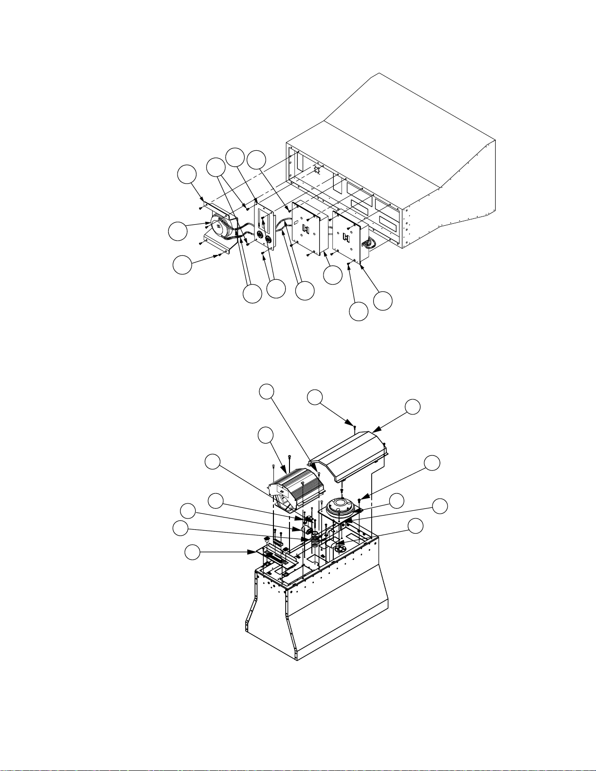
Figure 1. Panaray
Exploded View
5
2
19
12
11
13
6
7
15
4
1
3
10
Figure 2. Panaray Series II Exploded View
9
Page 10

DISASSEMBLY/ASSEMBLY PROCEDURES
3202™/4402™/9702™ SERIES I
Note: Numbers in parentheses correspond
to the item call outs in Figure 1.
1. Compression Driver Removal
1.1 Disconnect the Neutrik Speakon™
connector(s) and the weather protector, (if
used).
1.2 Disconnect the red and black wires (6)
from the compression driver terminals.
Note: On some models, the connectors
may have been soldered.
1.3 Remove the four screws (4) holding
the compression driver assembly (3) to the
cabinet.
1.4 Remove the four screws holding the
compression driver (2) to the mounting
plate.
2. Compression Driver Replacement
2.1 Place the new compression driver on
to the mounting plate, and secure it to the
plate.
2.2 Place the compression driver assembly (3) on to the cabinet and secure it to
the cabinet.
Note: Tighten screws in the following
order: clockwise with a torque setting of 5
inch-pounds. Counter clockwise with a
torque setting of 15 inch-pounds. Clockwise with a torque setting of 25 inchpounds.
2.3 Reconnect the red and black wires (6)
to the terminals on the driver.
3. M-10 Driver Removal
3.1 Perform procedure 1.1.
3.2 Remove the bottom two screws (5) on
the connector panel (7).
3.3 Loosen the two top screws on the
connector panel. This will allow room for
the M-10 driver when lifting it out of the
cabinet.
3.4 Remove the four screws (8) holding
the M-10 driver (1) to the cabinet.
Note: Do not let the driver fall out of the
cabinet.
3.5 Disconnect the green and white wires
(10) from the M-10 driver.
4. M-10 Driver Replacement
4.1 Reconnect the green and white wires
onto the new M-10 driver.
4.2 Place the new M-10 driver (1) onto the
cabinet, carefully routing the green and
white wires around the side of the driver.
4.3 Secure the M-10 driver to the cabinet.
4.4 Replace the two screws (5) in the
bottom of the connector panel, and tighten
all four screws.
4.5 Perform procedure 2.4 and 2.5.
Note: To remove the lower M-10 driver (9)
from the model 3202 simply remove the
four screws (11) holding the driver to the
cabinet, and disconnect the speaker wires.
2.4 Perform the test procedures on page
13.
2.5 Reconnect the Neutrik Speakon
connector to the speaker panel and replace the weather protector, (if used).
10
Page 11

DISASSEMBLY/ASSEMBLY PROCEDURES
3202™/4402™/9702™ SERIES II
Caution: The rear of the Panaray® LT
loudspeakers can become extremely hot
during normal use. Do not attempt to
service the loudspeakers until they have
cooled to room temperature.
Note: Numbers in parentheses correspond
to the item call outs in Figure 2.
1. Compression Driver Removal
1.1 Disconnect the Neutrik Speakon™
connector from the connector panel (6).
1.2 Remove the two screws (7) holding the
cover assembly on to the cabinet. Slide the
cover assembly (15) up and remove it from
the cabinet.
1.3 Disconnect the red and black wires
from the terminals of the compression
driver (1).
Note: On some models, the connectors
may have been soldered.
2.3 Reconnect the red and black wires
on the compression driver terminals.
Take care to place the red wire on the
positive(+) terminal and the black wire
on the negative (-) terminal.
2.4 Perform the test procedures on page
13.
2.5 Align the cover assembly (15) tabs
with the slots in the cabinet and slide the
cover into place. Secure the cover to the
cabinet.
2.6 Reconnect the Neutrik Speakon
connector to the connector panel.
3. Vee Four Driver Removal
3.1 Perform steps 1.1 and 1.2.
3.2 Disconnect the green and white wires
from the Vee Four terminals.
1.4 Remove the four screws (4) holding
the compression driver assembly (1) to the
cabinet.
1.5 Remove the compression driver assembly from the cabinet.
1.6 Remove the four screws holding the
compression driver to the mounting plate
(3).
2. Compression Driver Replacement
2.1 Place the new driver on to the mount-
ing plate (3) and secure it to the plate.
2.2 Place the compression driver assembly
(1) into the cabinet and secure it to the
cabinet.
3.3 Remove the four screws (5) holding
the Vee Four driver assembly (2) to the
cabinet.
3.4 Remove the Vee Four driver assembly
(2) from the cabinet.
4. Vee Four Driver Replacement
4.1 Place the new Vee Four driver assem-
bly into the cabinet.
4.2 Secure the driver assembly (2) to the
cabinet using the screws supplied with the
new driver assembly package.
4.3 Reconnect the green and white wires
to the terminals on the driver assembly.
Take care to place the green wire on to the
positive (+) terminal and the white wire on
to the negative (-) terminal.
11
4.4 Perform steps 2.4 thru 2.6.
Page 12

DISASSEMBLY/ASSEMBLY PROCEDURES
3202™/4402™/9702™ SERIES II
Note: The 3202 II loudspeaker has two V ee
Four driver assemblies. The cover does not
need to be removed to access the lower
driver assembly.
5. Vee Four Lower Driver Removal
5.1 Disconnect the two wires connected to
the terminals on the driver assembly.
5.2 Remove the four screws holding the
driver assembly to the cabinet.
5.3 Remove the driver assembly.
6. Vee Four Lower Driver Replacement
6.1 Place the new Vee Four driver assem-
bly onto the cabinet.
6.2 Secure driver assembly to the cabinet
using the screws provided in the new driver
assembly packaging.
8.3 Place the new inductor assembly (13)
into the cabinet and secure it to the cabinet.
Connect the wires to the capacitor and wire
harness.
8.4 Perform the test procedures on page
13.
8.5 Perform step and 2.5.
6.3 Perform the test procedures on page
13.
7. Crossover Component Removal
7.1 Perform steps 1.1 and 1.2.
7.2 To remove the capacitors remove the
screws from the bracket (12) and disconnect the wires.
7.3 To remove the inductor assembly (13)
remove the screw (19) from the center of
the inductor. Disconnect the inductor from
the capacitor and the wire harness and
remove the inductor.
8. Crossover Component Replacement
8.1 Reconnect the wires to the new ca-
pacitor and place it into the cabinet. Place
the bracket (12) over the capacitor and
secure it to the cabinet.
12
Page 13

DIAPHRAGM REPLACEMENT PROCEDURE
Note: Use a clean, well lit work area to
replace the diaphragm. The work area must
be free of magnetic materials that might be
attracted to the magnet in the compression
driver.
1. Rear Cover Removal
1.1 Carefully clean the outside of the
compression driver with a damp cloth.
1.2 Place the compression driver so the
rear is facing up.
1.3 Remove the three stainless steel
hexhead screws with a 5/32" hex wrench
by first loosening each screw one turn.
Then alternately loosen each screw until
they are removed from the rear cover.
1.4 Gently lift the rear cover straight up.
Set it down on its outside to keep the inside
clean.
2. Diaphragm Removal
2.1 Remove the black diaphragm assem-
bly by gently lifting and rotating it.
Note: If the gap is still not clean
replace the entire compression driver.
C. The front plate may have some small
smudges from fingerprints but there should
be no debris (from a shattered aluminum
diaphragm or any other source) and it
should feel smooth to the touch with no pits
in the metal.
4. Diaphragm Kit Replacement
4.1 Remove the replacement diaphragm
from its carton. Set it down so the coil is
facing up.
4.2 Grasp the diaphragm assembly around
its edges and gently place it onto the front
of the compression driver assembly.
Note: Take care not to damage the bobbin
as it comes in contact with the driver
assembly.
4.3 Slowly and gently rotate the diaphragm assembly so that the coil is worked
into the gap and the diaphragm assembly
rests smoothly against the front of the
compression driver.
3. Compression Driver Magnet Inspection
Procedure
3.1 Examine the gap in which the coil of
the diaphragm sits by doing the following
steps.
A. Gently insert one end of a piece of
paper (approximately 1" x 1/2") into the
gap. Move the paper around the perimeter
of the gap. You should not feel any debris
or obstructions with the paper.
B. To remove the debris (if any) from
the gap, fold a piece of masking tap so that
both sides are sticky. Insert the tape into
the gap and work into and around the gap,
removing any debris. Check the gap with a
piece of paper. Once the gap is clean make
sure that there is no debris on the front
plate.
4.4 Align the holes in the diaphragm
assembly with the holes in the compression
driver.
4.5 Place the rear cover back on by aligning the three screw holes and the three
post holes.
Note: Make sure the assembly fits together
flush, and the holes are aligned.
4.6 Place screw with lock washer into each
of the three holes. Tighten screws in this
order: clockwise with a torque setting of 5
inch-pounds. Counter clockwise with a
torque setting of 15 inch-pounds. Clockwise
with a torque setting of 25 inch-pounds.
4.7 Perform step 2 in the Disassembly/
Assembly Procedures.
4.8 Perform Test Procedures.
13
Page 14

High-Frequency -
Mid-Range -
High-Frequency +
Mid-Range +
IF THE JUMPERS ARE NOT USED
CONNECT TO THE TERMINAL BLOCK
ACCORDING TO THIS PIN LAY-OUT.
TEST PROCEDURES
pin 1 +
pin 2 +
pin 1 -
pin 2 -
CONNECT TEST CABLES
HERE AT THE TERMINAL
BLOCK.
JUMPER
JUMPERIF JUMPERS ARE USED
Figure 3. Connection Diagram
Note: Connect the cables to the terminal
block as shown in Figure 3.
1. Rub and Tick Test
1.1 Apply an 8Vrms, 10Hz signal to the
input terminals of the speaker.
1.2 No extraneous noise such as rubbing,
scraping or ticking should be heard.
2. Phase Test
2.1 Disconnect the connectors at the V-4
or M-10 terminals. Momentarily apply
±1Vdc to the terminals. Observe polarity
8
when connecting the dc power supply. All
the drivers should move outward.
3. Frequency Power Sweep Test
3.1 Apply an 8Vrms, 10Hz signal to the
speaker input terminals.
3.2 Sweep the Loudspeaker from 10Hz to
2kHz.
3.3 Lower the applied voltage to 4Vrms
and sweep the loudspeaker from 1kHz to
5kHz.
3.4 Listen for any buzzes, rattles or other
extraneous noises from the loudspeaker.
14
Page 15

PART LIST NOTES
1. There are two high-frequency compression drivers available.
Part number 176605 is used for the original Panaray
Part number 186100 is used for the Panaray LT Series II Systems.
2. The replacement diaphragm kit is used to repair both the original and series II high-frequency compression drivers.
3. There are two Vee Four mid-range driver assemblies used on the 3202™ II.
4. There are two M-10 drivers used on the 3202 panaray loudspeaker.
®
LT Systems.
15
Page 16

PANARAY® LT SERIES II PART LIST
Item
Number
Desription Qty Part
Number
1 Driver, Compression, T1.4 HP 1 186100 1
1 Replacement Diaphragm Kit (T1.4) 1 181470 2
2 Sys Assy, Vee Four, Blk 1 190700-001 3
3 Bracket, High Freq. Driver 1 176896
4 Screw, Mach, .25-20, Pan, XREC 12 176801-16
5 Screw, Mach, . 25-20, Flat, XREC, SS 4 176614-08
6 Connector Panel Assy, LT II 1 187976-03 3202™-II
6 Connector Panel Assy, LT II 1 187976-02
7 Screw, Tapp, 8-11X.75, Pan, XRC/SQ 8 187942-12
8 Conn, Speakon, Panel Mount 2 187887
9 Clip, Tinnerman 2 187943
10 Cap, Filter, Oval, 10%, 6uF 1 187890
11 Cap, Filter, Oval, 3uF 1 176668
12 Strap, Mounting, Cap 2 176669
13 Inductor, .63uH 1 187889
14 Spacer, Round, 1.150x.074 1 130913
15 Cover Assy, Back, LT II 1 176897-01 3202-II
15 Cover Assy, Back, LT II 1 176897-02
16 Label, Bose, Logo 1 183067
17 Clip, Cable, Dbl Face Adh, .25" 4 145716
18 Connector, Terminal Blockstrip 1 188629-004
19 Screw, Pan Head, 1.5" #6-32 1 146092-24
20 Screw, Mach, 6-32, FH, XREC 2 187935-10
21 Nut, Hex, W/Lock washer 2 133803-06
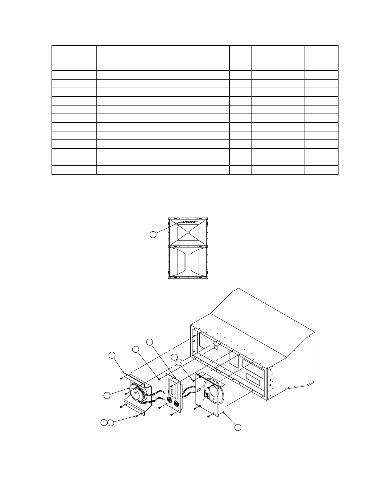
Note
NL4MP
1+
2-
1-
2+
8
(QTY 4)
5
4
2
19
11
(QTY 2)
13
14
(QTY 2)
21
20
18
(QTY 2)
27
V4
V4
PIN 1PIN 2-
PIN 2+
PIN 1+
8
(QTY 2)
7
6
(QTY 2)
9
(QTY 4)
17
CLIP
15
7
(QTY 2)
16
(QTY 4)
4
5
3
1
(QTY 4)
8
(QTY 2)
12
10
Figure 4. Panaray® Series II Exploded View
Page 17
PANARAY® LT PART LIST
Item
Number
Description Qty Part
Number
1 Driver Assy, Midrange, 10" M10 1 176606 4
2 Driver, Compression, T1.4 1 176605
2 Diaphragm Kit, Driver, T1.4 1 181470 2
3 Bracket, High-Freq. Driver 1 176665
4 Screw, Mach, .25-20, Flat, XREC 8 176601-12
5 Screw, Mach, .25-20, Pan, XREC 4 176801-16
6 Screw, Mach, .25-20, Flat, XREC, SS 8 176614-08
7 Connector Panel Assy 1 176675 3202™
7 Connector Panel Assy 1 176720 4402™
7 Connector Panel Assy 1 176864 9702™
7 Cap, Filter, Oval , 3uF 1 176668
7 Stip, Mounting, 3uF Cap 1 176669
8 Label, Bose, Logo 1 183067
Note
8
(NOTE 1)
3
2
7
5
6
4
4
6
1
Figure 5. Panaray Exploded View
Page 18

PACKING PART LIST
Item
Number
1 Packing, Insert, eps 148044 4
2 Poly B ag N/A 1 3202™ II
2 Poly B ag N/A 1 4402™ II
2 Poly B ag N/A 1 9702™ II
3 Tray, Packing 181 674 2 3202 II
3 Tray, Packing 181 676 2 4402 II
3 Tray, Packing 181 678 2 9702 II
4 Packing, Insert, Crease
Sheet
Desription Part
Number
181679 2
Oty Note
3
4
3
2
1
Figure 6. Packing
18
 Loading...