

Page 1

General-Purpose AC Servo
J2-Super
Series
SSCNET Compatible
MR-J2S- B
Servo Amplifier
Instruction Manual
B
Page 2
Safety Instructions
(Always read these instructions before using the equipment.)
Do not attempt to install, ope rate, maint ain or inspect the servo amplif ier and servo m otor until you hav e read
through this I nstruction M anual, Insta llation guid e, Servo motor Instructio n Manual and appen ded docum ents
carefully and can us e th e equ i pment correctl y. D o no t us e t he s er vo amplifier an d servo motor un ti l you have a
full knowledge of the equipment, safety information and instructions.
In this Instruction Manual, the safety instruction levels are classified into "WARNING" and "CAUTION".
Indicates that incorrect handling may cause hazardous conditions,
WARNING
CAUTION
Note that the CAUTION level may lead to a serious consequence according to conditions. Please follow the
instructions of both levels because they are important to personnel safety.
What must not be done and what must be done are indicated by the following diagrammatic symbols:
resulting in death or severe injury.
Indicates that incorrect handling may cause hazardous conditions,
resulting in medium or slight injury to personnel or may cause physical
damage.
: Indicates what must not be done. For example, "No Fire" is indicated by
: Indicates what must be done. For example, grounding is indicated by
In this Instructi on Manual, ins tructions at a lo wer level t han the abo ve, instruc tions for other func tions, an d so
on are classified into "POINT".
After reading this Instruction Manual, always keep it accessible to the operator.
.
.
A - 1
Page 3
1. To prevent electric shock, note the following:
WARNING
Before wiring or inspection, switch power off and wait for more than 10 minutes. Then, confirm the voltage
is safe with voltage tester. Otherwise, you may get an electric shock.
Connect the serv o a mpl i fie r and se rvo mot o r to grou nd .
Any person who is involved in wiring and inspection should be fully competent to do the work.
Do not attempt to wire the servo amplifier and servo motor until they have been installed. Otherwise, you
may get an electric shock.
Operate the switches with dry hand to prevent an electric shock.
The cables should not be damaged , stressed, loaded, or pinched. Othe rwi se, you may get an ele ctric shoc k.
2. To prevent fire, note the following:
CAUTION
Do not install the servo amplifier, servo motor and regenerative brake resistor on or near combustibles.
Otherwise a fire may cause.
When the servo amplifier has become faulty, switch off the main servo amplifier power side. Continuous
flow of a large current may cause a fire.
When a regenerative brake resistor is used, use an alarm signal to switch main power off. Otherwise, a
regenerative brake transistor fault or the like may overheat the regenerative brake resistor, causing a fire.
3. To prevent injury, note the follow
CAUTION
Only the voltage specified in the Instruction Manual should be applied to each terminal. Otherwise, a burst,
damage, etc. may occur.
Connect the terminals correctly to prevent a burst, damage, etc.
Ensure that polarity ( , ) is correct. Otherwise, a burst, damage, etc. may occur.
During power-on or for some time after power-off, do not touch or close a parts (cable etc.) to the servo
amplifier heat sink, regenerative brake resistor, servo motor, etc. Their temperatures may be high and you
may get burnt or a parts may dameged.
A - 2
Page 4
4. Additional instructions
The following instructions should also be fully noted. Incorrect handling may cause a fault, injury, electric
shock, etc.
(1) Transportation and installation
CAUTION
Transport the products correctly according to their weights.
Stacking in excess of the specified number of products is not allowed.
Do not carry the motor by the cables, shaft or encoder.
Do not hold the front cover to transport the controller. The controller may drop.
Install the servo amplifier in a load-bearing place in accordance with the Instruction Manual.
Do not climb or stand on servo equipment. Do not put heavy objects on equipment.
The controller and servo motor must be installed in the specified direction.
Leave specified clearances between the servo amplifier and control enclosure walls or other equipment.
Do not install or operate the servo amplifier and servo motor which has been damaged or has any parts
missing.
Provide adequate protection to prevent screws and other conductive matter, oil and other combustible
matter from entering the servo amplifier.
Do not drop or strike servo amplifier or servo motor. Isolate from all impact loads.
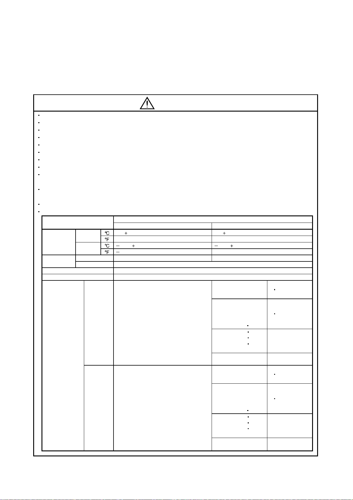
Use the servo amplifier and servo motor under the following environmental conditions:
Environment
Ambient
temperature
Ambient
humidity
Ambience Indoors (no direct sunlight) Free from corrosive gas, flammable gas, oil mist, dust and dirt
Altitude Max. 1000m (3280 ft) above sea level
Vibration
Operation
Storage
Operation 90%RH or less (non-condensing) 80%RH or less (non-condensing)
Storage 90%RH or less (non-condensing)
[ ]0 to 55 (non-freezing) 0 to 40 (non-freezing)
[
] 32 to 131 (non-freezing) 32 to 104 (non-freezing)
[ ] 20 to 65 (non-freezing) 15 to 70 (non-freezing)
[
] 4 to 149 (non-freezing) 5 to 158 (non-freezing)
[m/s2] 5.9 or less
2
] 19.4 or less
[ft/s
Servo amplifier Servo motor
Conditions
HC-UFS202 to 502
HC-SFS502 to 702
HC-UFS202 to 502
HC-SFS502 to 702
HC-KFS Series
HC-MFS Series
HC-UFS13 to 73
HC-SFS81
HC-SFS52 to 152
HC-SFS53 to 153
HC-RFS Series
HC-UFS 72
HC-SFS121 201
HC-SFS202
HC-SFS203
HC-SFS301
HC-KFS Series
HC-MFS Series
HC-UFS 13 to 73
HC-SFS81
HC-SFS52 to 152
HC-SFS53 to 153
HC-RFS Series
HC-UFS 72
HC-SFS121 201
HC-SFS202
HC-SFS203
HC-SFS301
152
352
353
152
352
353
X
Y : 49
Y : 24.5
X
X : 24.5
Y : 49
X : 24.5
Y : 29.4
X
Y : 161
Y : 80
X
X : 80
Y : 161
X : 80
Y : 96
A - 3
Page 5
CAUTION
Securely attach the servo motor to the machine. If attach insecurely, the servo motor may come off during
operation.
The servo motor with reduction gear must be installed in the specified direction to prevent oil leakage.
For safety of personnel, always cover rotating and moving parts.
Never hit the servo motor or shaft, especially when coupling the servo motor to the machine. The encoder
may become faulty.
Do not subject the servo motor shaft to more than the permissible load. Otherwise, the shaft may break.
When the equipment has been stored for an extended period of time, consult Mitsubishi.
(2) Wiring
CAUTION
Wire the equipment correctly and securely. Otherwise, the servo motor may misoperate.
Do not install a power capacitor, surge absorb er or radio nois e filter (FR-BI F option) bet ween the servo
motor and servo amplifier.
Connect the output terminals (U, V, W) correctly. Otherwise, the servo motor will operate improperly.
Do not connect AC power directly to the servo motor. Otherwise, a fault may occur.
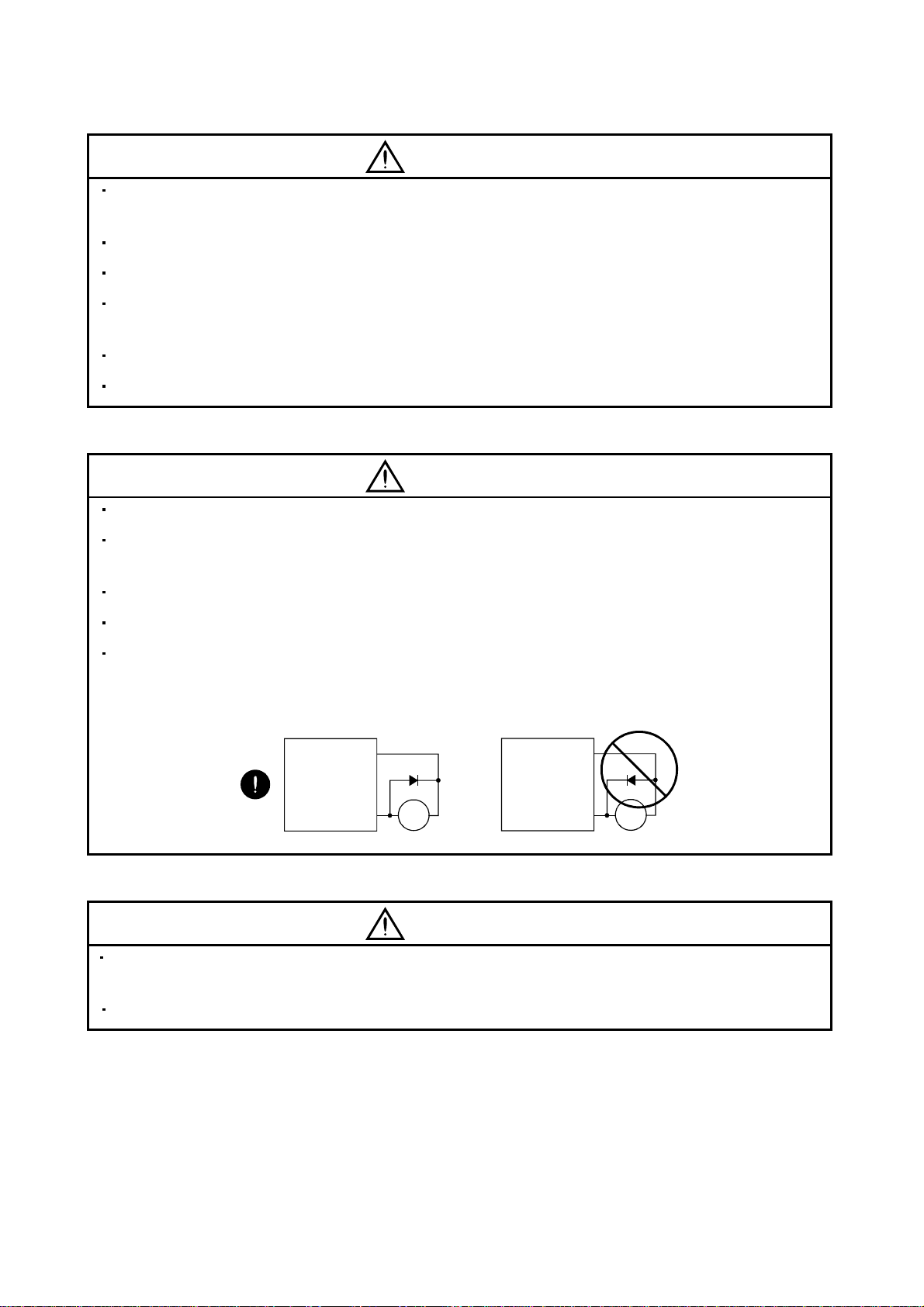
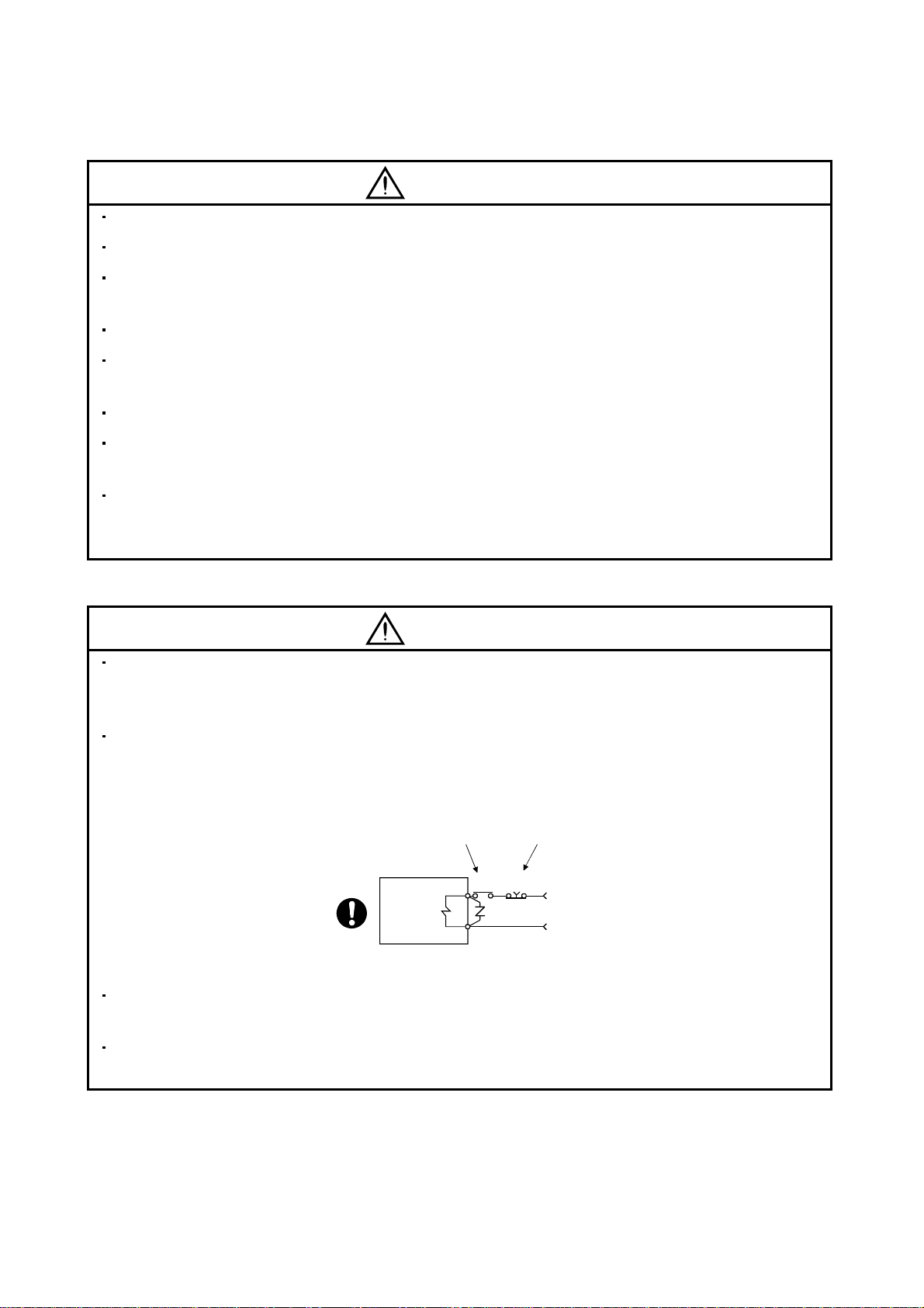
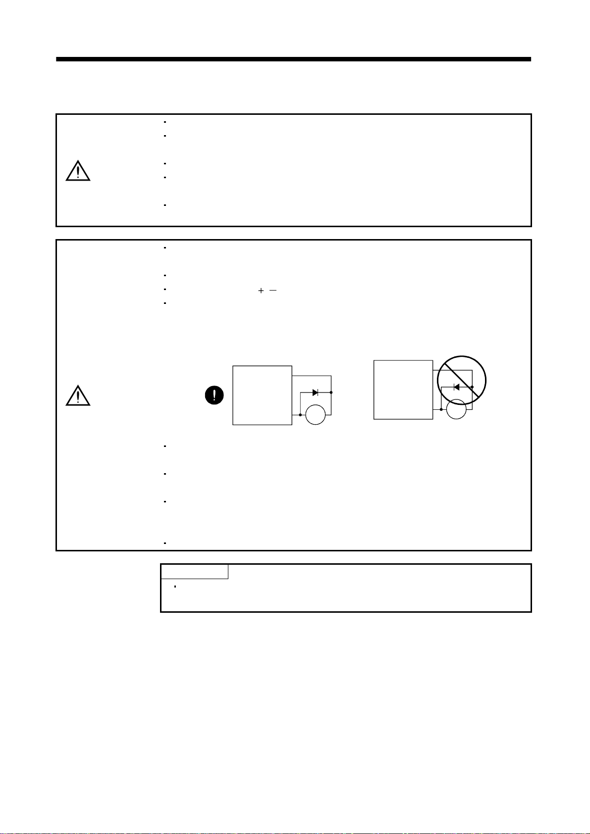
The surge absorbi ng diode in stal le d on th e DC ou t put si gna l r el ay must be wired in the specifie d dire ctio n .
Otherwise, the forced stop and other protective circuits may not operate.
Servo
Amplifier
(24VDC)
Control
output
signal
COM
RA
Servo
Amplifier
(24VDC)
Control
output
signal
COM
RA
(3) Test run adjustment
CAUTION
Before operat ion, check the par ameter setti ngs. Im proper sett ings m ay cause som e mac hines to p erform
unexpected operation.
The parameter settings must not be changed excessively. Operation will be insatiable.
A - 4
Page 6
(4) Usage
CAUTION
Provide a forced stop circuit to ensure that operation can be stopped and power switched off immediately.
Any person who is involved in disassembly and repair should be fully competent to do the work.
Before resettin g an alarm , make sure th at the run s igna l is of f to pr event an acc ident. A sudden r est art is
made if an alarm is reset with the run signal on.
Do not modify the equipment.
Use a noise filter, etc. to minim i ze the inf lue nce of electr om agne tic int erfer enc e, wh ich m ay b e ca use d b y
electronic equipment used near the servo amplifier.
Use the servo amplifier with the specified servo motor.
The electromagnetic brake on the servo motor is designed to hold the motor shaft and should not be used
for ordinary braking.
For such reas ons as servic e life and m echanical struc ture (e.g. wher e a ballscre w and the servo motor
are coupled via a tim ing belt) , the e lectrom agnet ic br ake m ay not ho ld the motor shaft. T o ens ure saf ety,
install a stoppe r on the machin e si de.
(5) Corrective actions
CAUTION
When it is ass umed that a hazardous c ondition ma y take place a t the occur d ue to a power failure or a
product fault, use a servo motor with electromagnetic brake or an external brake mechanism for the
purpose of prev en ti on .
Configure th e electromagnet ic brake circu it so that it is activated n ot only by t he servo amplifier s ignals
but also by a forced stop signal.
Contacts must be open when
servo-on signal is off, when an
alarm (trouble) is present and when
an electromagnetic brake signal.
Servo motor
Electromagnetic brake
When any alarm has occurred, eliminate its cause, ensure safety, and deactivate the alarm before
restarting operation.
When power is restor ed after an inst antaneous power failu re, keep away from the machine because th e
machine may be restarted suddenly (design the machine so that it is secured against hazard if restarted).
Circuit must be
opened during
forced stop signal.
EM1RA
24VDC
A - 5
Page 7
(6) Maintenance, inspection and parts replacement
CAUTION
With age, the electrolytic capacitor will deteriorate. To prevent a secondary accident due to a fault, it is
recommended to replace the electrolytic capacitor every 10 years when used in general environment.
Please consult our sales representative.
(7) Disposal
CAUTION
Dispose of the product as general industrial waste.
(8) General instruction
To illustrate details, the equipment in the diagrams of this Instruction Manual may have been drawn
without covers and safet y guards. W hen the equipm ent is operate d, the covers and safet y guards must
be installed as specified. Operation must be performed in accordance with this Instruction Manual.
A - 6
Page 8
COMPLIANCE WITH EC DIRECTIVES
1. WHAT ARE EC DIRECTIVES?
The EC directives were issued to standardize the regulations of the EU countries and ensure smooth
distribution of safety-guaranteed products. In the EU countries, the machinery directive (effective in
January, 1995), EMC dire ctive (effecti ve in January, 1996) and low voltage directive (effective in January,
1997) of the EC directives require that products to be sold should meet their fundamental safety
requirements and carry the CE marks (CE mar king). CE marking applies to machines and equipment
into which servo amplifiers have been installed.
(1) EMC directive
The EMC directive applies not to the servo units alone but to servo-incorporated machines and
equipment. This requires the EMC filters to be used with the servo-incorporated machines and
equipment to comply with the EMC directive. For specific EMC directive conforming methods, refer to
the EMC Installation Guidelines (IB(NA)67310).
This servo is certified by TUV, third-party assessment organization, to comply with the EMC di rective
in the conforming methods of the EMC Installation Guidelines.
(2) Low voltage di re ctiv e
The low voltage directive applies also to servo units alone. Hence, they are designed to comply with
the low voltage directive.
This servo is certified by TUV, third-party assessment orga nization, to comply with the low voltage
directive.
(3) Machine directive
Not being machines, the servo amplifiers need not comply with this directive.
2. PRECAUTIONS FOR COMPLIANCE
(1) Servo amplifiers and servo motors used
Use the servo amplifiers and servo motors which comply with the standard model.
Servo amplifie r :MR-J2S-10B t o MR-J2 S -700 B
MR-J2S-10B1 to MR-J2S-40B1
Servo motor :HC-KFS
HC-MFS
HC-SFS
HC-RFS
HC-UFS
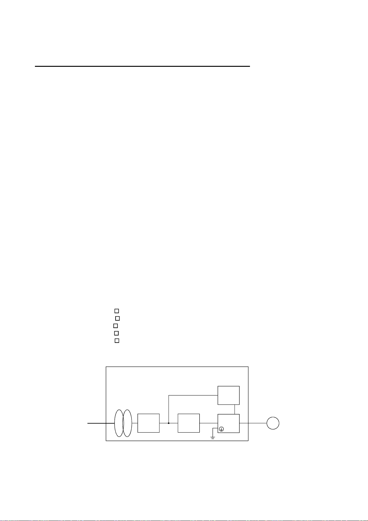
(2) Configuration
Control box
Reinforced
insulating type
Reinforced
insulating
transformer
No-fuse
breaker
NFB
Magnetic
contactor
MC
24VDC
power
supply
Servo
amplifier
Servo
motor
SM
(3) Environment
Operate the servo amplifier at or above the contamination level 2 set forth in IEC664. For this
purpose, install the servo amplifier in a control box which is protected against water, oil, carbon, dust,
dirt, etc. (IP54).
A - 7
Page 9
(4) Power supply
(a) Operate the servo amplifier to meet the requirements of the overvoltage category II set forth in
IEC664. For this purpose, a reinforced insulating transformer conforming to the IEC or EN
standard should be used in the power input section.
(b) When supplying interface power from external, use a 24VDC power supply which has been
insulation-reinforced in I/O.
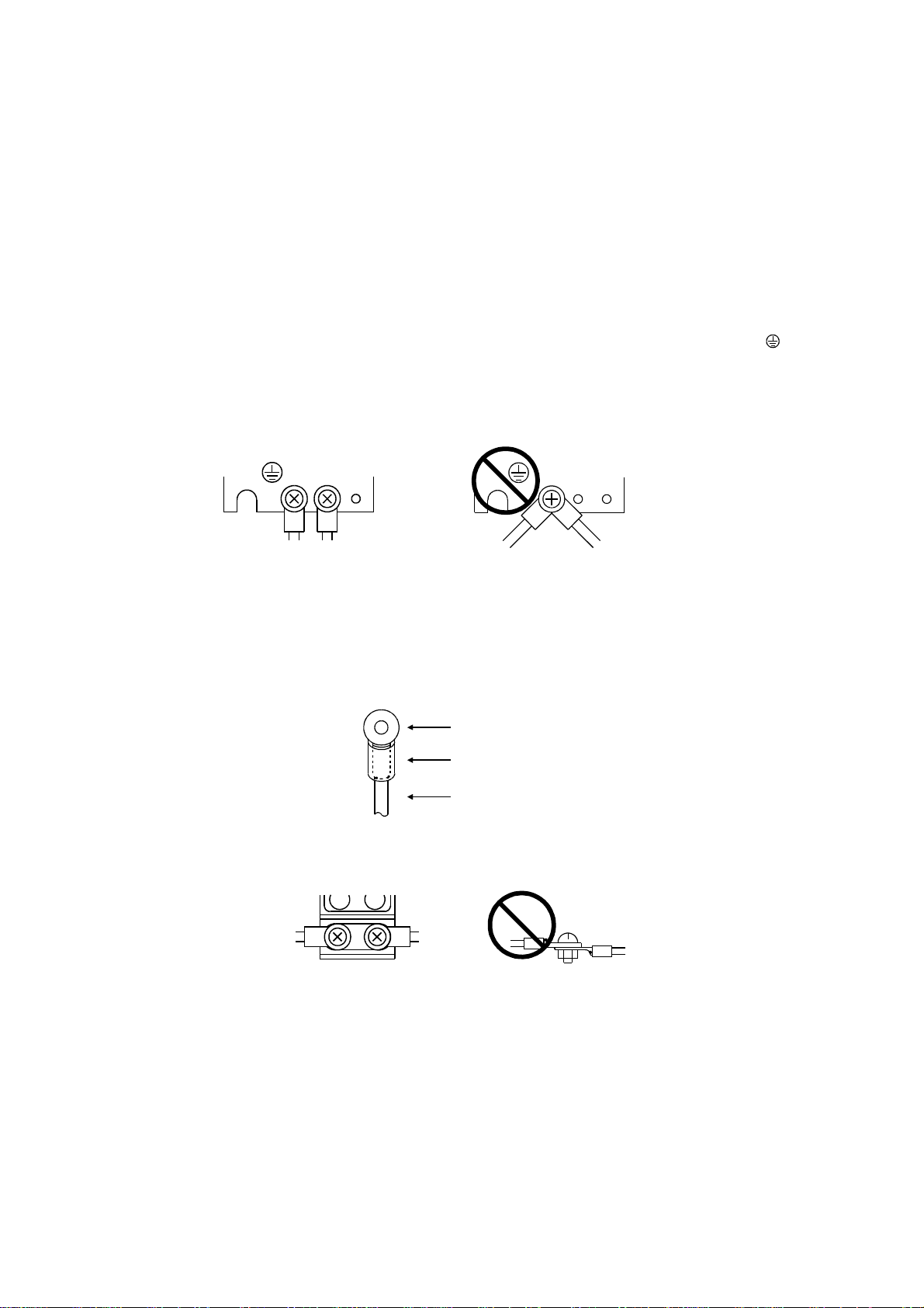
(5) Grounding
(a) To prevent an electric shock, always connect the protective earth (PE) terminals (marked
servo amplifier to the protective earth (PE) of the control box.
(b) Do not co nnect two g round c ables to the same pro tective e arth (PE) terminal. Always c onnect the
cables to the terminals one-to-one.
) of the
PE terminals
PE terminals
(c) If a leakage current breaker is used to prevent an electric shock, the protective earth (PE) terminals
of the servo amplifier must be con ne ct ed t o t h e c orr espo ndi n g eart h te rmin als .
(6) Wiring
(a) The cables to be connected to the terminal block of the servo amplifier must have crimping
terminals provided with insulating tubes to prevent contact with adjacent terminals.
Crimping terminal
Insulating tube
Cable
(b) When the servo motor has a power supply lead , use a fixed terminal block to connect it with the
servo amplifier. Do not connect cables directly.
Terminal block
A - 8
Page 10

(7) Auxiliary equipment and options
(a) The no-fuse breaker and magnetic contactor used should be the EN or IEC standard-compliant
products of the models described in Section 12.2.2.
(b) The sizes of the cable s described in Section 12.2. 1 meet the following req uirements. To meet t he
other requirements, follow Table 5 and Appendix C in EN60204-1.
Ambient tempera t ur e: 40 (104 ) [ ( )]
Sheath: PVC (polyvinyl chloride)
Installed on wall surface or open table tray
(c) Use the EMC filter for noise reduction. The radio noise filter (FR-B IF) is not required.
(8) Performing EMC tests
When EMC tests are ru n on a machine/device in to which the servo amplifier has been installed, i t
must conform to the electromagnetic compatibility (immunity/emission) standards after it has
satisfied the operating environment/electrical equipment specificati ons.
For the other EMC directive guidelines on the servo amplifier, refer to the EMC Installation
Guidelines(IB(NA)67310).
A - 9
Page 11
CONFORMANCE WITH UL/C-UL STANDAR D
(1) Servo amplifiers and servo motors used
Use the servo amplifiers and servo motors which comply with the standard model.
Servo amplifie r :MR-J2S-10B t o MR-J2 S -700 B
MR-J2S-10B1 to MR-J2S-40B1
Servo motor :HC-KFS
HC-MFS
HC-SFS
HC-RFS
HC-UFS
(2) Installation
Install a fan of 100CFM air flow 10.16 cm (4 in) above the servo amplifier or provide cooling of at least
equivalent capability.
(3) Short circuit rating
This servo amplifier conforms to the circuit whose peak current is limited to 5000A or less. Having
been subjected to the short-circuit tests of the UL in the alternating-current circuit, the servo
amplifier conforms to the above circuit.
(4) Capacitor discharge time
The capacitor disc har ge tim e is a s listed belo w. To ensu re safety , do no t touch th e ch arg ing sec tion for
10 minutes after power-off.
Servo amplifier
MR-J2S-10B(1) 20B(1) 1
MR-J2S-40B(1) 60B 2
MR-J2S-70B to 350B 3
MR-J2S-500B 700B 5
(5) Options and auxiliary equipment
Use UL/C-UL standard-compliant products.
<<About the manual s>>
This Instruction Manua l and the MEL SERVO Se rvo Moto r Ins truc tion M anua l are re quired if yo u use
the General-Purpose AC servo MR-J2S-B for the first time. Always purchase them and use the MRJ2S-B safely.
Also read the manual of the servo system controller.
Relevant manuals
Discharge time
[min]
Manual name Manual No.
MELSERVO-J2-Super Series To Use the AC Servo Safely
(Packed with the servo amplifier)
MELSERVO Servo Motor Instruction Manual SH(NA)3181
EMC Installation Guidelines IB(NA)67310
A - 10
IB(NA)0300010
Page 12

CONTENTS
1. FUNCTIONS AND CONFIGURATION 1- 1 to 1-18
1.1 Introduction.............................................................................................................................................. 1- 1
1.2 Function block diagram ..........................................................................................................................1- 2
1.3 Servo amplifier standard specifications................................................................................................1- 3
1.4 Function list.............................................................................................................................................1- 4
1.5 Model code definition ..............................................................................................................................1- 5
1.6 Combination with servo motor...............................................................................................................1- 6
1.7 Structure...................................................................................................................................................1- 7
1.7.1 Parts identification...........................................................................................................................1- 7
1.7.2 Removal and reinstallation of the front cover ..............................................................................1-11
1.8 Servo system with auxiliary equipment...............................................................................................1-13
2. INSTALLATION 2- 1 to 2- 4
2.1 Environmental conditions.......................................................................................................................2- 1
2.2 Installation direction and clearances ....................................................................................................2- 2
2.3 Keep out foreign materials .....................................................................................................................2- 3
2.4 Cable stress..............................................................................................................................................2- 4
3. SIGNALS AND WIRING 3- 1 to 3-26
3.1 Connection example of control signal system.......................................................................................3- 2
3.2 I/O signals................................................................................................................................................. 3- 4
3.2.1 Connectors and signal arrangements.............................................................................................3- 4
3.2.2 Signal explanations ..........................................................................................................................3- 5
3.3 Alarm occurrence timing chart ..............................................................................................................3- 6
3.4 Interfaces.................................................................................................................................................. 3- 7
3.4.1 Common line .....................................................................................................................................3- 7
3.4.2 Detailed description of the interfaces.............................................................................................3- 8
3.5 Power line circuit....................................................................................................................................3-11
3.5.1 Connection example.........................................................................................................................3-11
3.5.2 Terminals..........................................................................................................................................3-13
3.5.3 Power-on sequence...........................................................................................................................3-14
3.6 Connection of servo amplifier and servo motor...................................................................................3-15
3.6.1 Connection instructions ..................................................................................................................3-15
3.6.2 Connection diagram.........................................................................................................................3-15
3.6.3 I/O terminals....................................................................................................................................3-17
3.7 Servo motor with electromagnetic brake .............................................................................................3-19
3.8 Grounding................................................................................................................................................3-22
3.9 Servo amplifier terminal block (TE2) wiring method.........................................................................3-23
3.10 Instructions for the 3M connector.......................................................................................................3-24
3.11 Control axis selection ...........................................................................................................................3-25
4. OPERATION AND DISPLAY 4- 1 to 4- 8
4.1 When switching power on for the first time..........................................................................................4- 1
1
Page 13

4.2 Start up.....................................................................................................................................................4- 2
4.3 Servo amplifier display ...........................................................................................................................4- 4
4.4 Test operation mode................................................................................................................................4- 6
5. PARAMETERS 5- 1 to 5-18
5.1 Parameter write inhibit.......................................................................................................................... 5- 1
5.2 Lists...........................................................................................................................................................5- 1
5.3 Analog output..........................................................................................................................................5-11
5.4 Replacement of MR-J2-
5.4.1 Main modifications made to the parameters ................................................................................5-14
5.4.2 Explanation of the modified parameters.......................................................................................5-15
6. GENERAL GAIN ADJUSTMENT 6- 1 to 6-12
6.1 Different adjustment methods ...............................................................................................................6- 1
6.1.1 Adjustment on a single servo amplifier.......................................................................................... 6- 1
6.1.2 Adjustment using servo configuration software............................................................................6- 3
6.2 Auto tuning ..............................................................................................................................................6- 4
6.2.1 Auto tuning mode .............................................................................................................................6- 4
6.2.2 Auto tuning mode operation............................................................................................................6- 5
6.2.3 Adjustment procedure by auto tuning............................................................................................6- 6
6.2.4 Response level setting in auto tuning mode...................................................................................6- 7
6.3 Manual mode 1 (simple manual adjustment).......................................................................................6- 8
6.3.1 Operation of manual mode 1 ...........................................................................................................6- 8
6.3.2 Adjustment by manual mode 1 .......................................................................................................6- 8
6.4 Interpolation mode .................................................................................................................................6-11
6.5 Differences in auto tuning between MELSERVO-J2 and MELSERVO-J2-Super..........................6-12
6.5.1 Response level setting ..................................................................................................................... 6-12
6.5.2 Auto tuning selection.......................................................................................................................6-12
B by MR-J2S- B....................................................................................... 5-14
7. SPECIAL ADJUSTMENT FUNCTIONS 7- 1 to 7- 4
7.1 Function block diagram ..........................................................................................................................7- 1
7.2 Machine resonance suppression filter...................................................................................................7- 1
7.3 Adaptive vibration suppression control.................................................................................................7- 3
7.4 Low-pass filter ......................................................................................................................................... 7- 4
8. INSPECTION 8- 1 to 8- 2
9. TROUBLESHOOTING 9- 1 to 9- 8
9.1 Alarms and warning list.........................................................................................................................9- 1
9.2 Remedies for alarms................................................................................................................................9- 2
9.3 Remedies for warnings............................................................................................................................9- 7
10. OUTLINE DIMENSION DRAWINGS 10- 1 to 10- 8
10.1 Servo amplifiers...................................................................................................................................10- 1
10.2 Connectors............................................................................................................................................10- 6
2
Page 14

11. CHARACTERISTICS 11- 1 to 11- 8
11.1 Overload protection characteristics...................................................................................................11- 1
11.2 Power supply equipment capacity and generated loss....................................................................11- 3
11.3 Dynamic brake characteristics...........................................................................................................11- 5
11.4 Encoder cable flexing life....................................................................................................................11- 7
12. OPTIONS AND AUXILIARY EQUIPMENT 12- 1 to 12-36
12.1 Options..................................................................................................................................................12- 1
12.1.1 Regenerative brake options.........................................................................................................12- 1
12.1.2 Brake unit......................................................................................................................................12- 7
12.1.3 Power return converter................................................................................................................12- 9
12.1.4 Cables and connectors.................................................................................................................12-12
12.1.5 Maintenance junction card (MR-J2CN3TM) ............................................................................12-21
12.1.6 Battery (MR-BAT, A6BAT).........................................................................................................12-22
12.1.7 Servo configurations software ....................................................................................................12-23
12.2 Auxiliary equipment ..........................................................................................................................12-24
12.2.1 Recommended wires....................................................................................................................12-24
12.2.2 No-fuse breakers, fuses, magnetic contactors...........................................................................12-26
12.2.3 Power factor improving reactors................................................................................................12-26
12.2.4 Relays............................................................................................................................................12-27
12.2.5 Surge absorbers ...........................................................................................................................12-27
12.2.6 Noise reduction techniques.........................................................................................................12-27
12.2.7 Leakage current breaker.............................................................................................................12-33
12.2.8 EMC filter.....................................................................................................................................12-35
13. ABSOLUTE POSITION DETECTION SYSTEM 13- 1 to 13- 4
13.1 Features................................................................................................................................................13- 1
13.2 Specifications .......................................................................................................................................13- 2
13.3 Battery installation procedure...........................................................................................................13- 3
13.4 Confirmation of absolute position detection data.............................................................................13- 4
3
Page 15

Optional Servo Motor Instruction Manual CONTENTS
The rough table of contents of the optional MELSERVO Servo Motor Instruction Manual is in troduced
here for your reference. Note that the contents of the Servo Motor Instruction Manual are not included in
the Servo Amplifier Instruction Manual.
1. INTRODUCTION
2. INSTALLATION
3. CONNECTORS USED FOR SERVO MOTOR WIRING
4. INSPECTION
5. SPECIFICATIONS
6. CHARACTERISTICS
7. OUTLINE DIMENSION DRAWINGS
8. CALCULA TI ON ME TH O DS F OR DES I G NI N G
4
Page 16

1. FUNCTIONS AND CONFIGURATION
1. FUNCTIONS AND CONFIGURATION
1.1 Introduction
The Mitsubishi MELSERVO-J2-Super series general-purpose AC servo is ba sed on the MELSERVO-J2
series and has further higher performance and higher functions.
It is connected with a servo system controller or simila r device via a serial bus (SSCNE T) and the servo
amplifier reads position data directly to perform operation.
Data from a command unit controls the speed and rotation direction of the servo motor and executes
precision positioning.
A torque limit is imposed on the servo amplifier by the clamp circuit to protect the power transistor in the
main circuit from overcurrent due to sudden acceleration/deceleration or overload. The torque limit value
can be changed to any value with an external analog input or the parameter.
As this new series has the RS-232C serial communication function, a servo configuration softwareinstalled personal computer or the like can be used to perform p arameter setting, test operation, status
display monitoring, gain adjustment, etc.
With real-time auto tuning, you can automatically adjust the servo gains according to the machine.
The MELSERVO-J2-Super series servo motor is equipped with an absolute position encoder which has
the resolution of 131072 pulses/rev to ensure more accura te control as compared to the MELSERVO-J2
series. Simply adding a battery to the servo amplifier makes up an abso lute position dete ction system.
This makes home position return unnecessary at power-on or alarm occurrence by setting a home position
once.
1 - 1
Page 17
1. FUNCTIONS AND CONFIGURATION
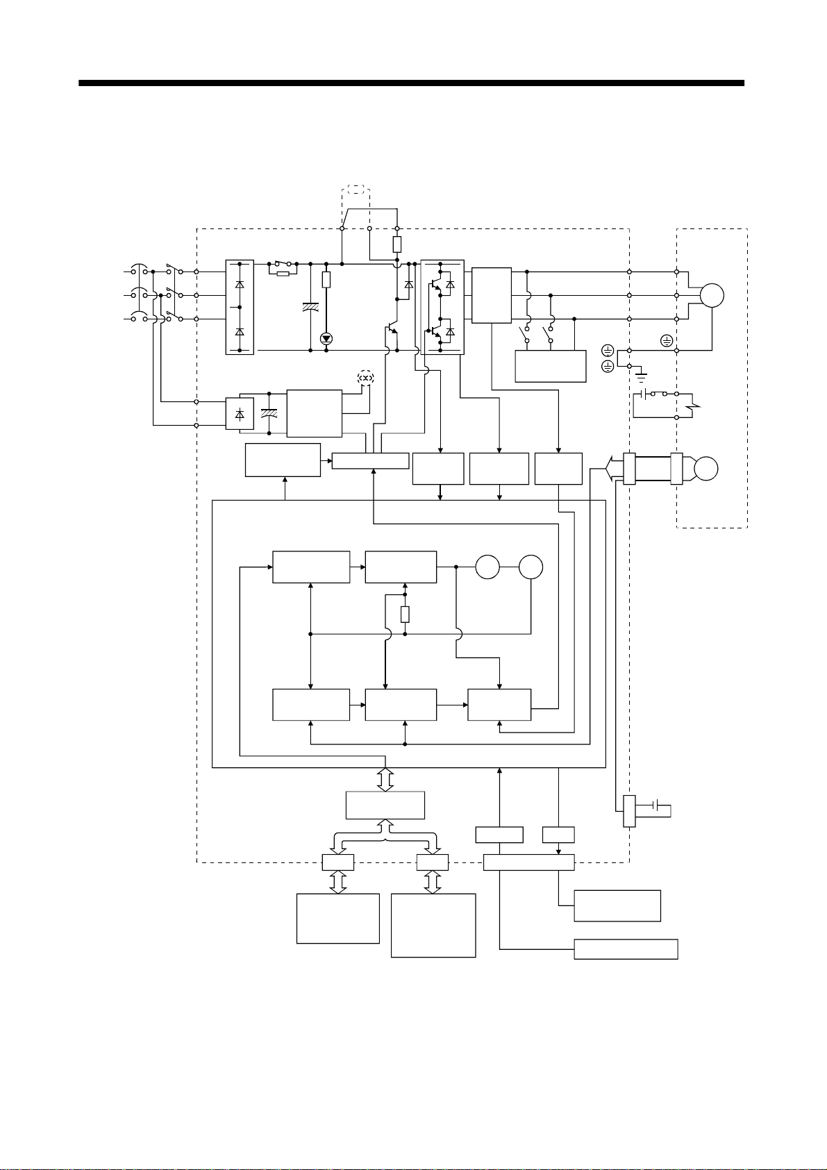
1.2 Function block diagram
The function block diagram of this servo is shown below.
Regenerative brake option
(Note 3)
(Note 2)
Power
NFB MC
supply
3-phase
200 to
230VAC,
1-phase
230VAC or
1-phase
100to120VAC
Servo amplifier
L
1
2
L
3
L
(MR-J2S-200B or more)
11
L
21
L
P
RADS
Regenerative
brake
transistor
CHARGE
lamp
Fan
Control
power
supply
D
C
(Note 1)
Current
detector
Dynamic
brake
Servo motor
E1
E2
U
V
W
SM
Electromagnetic
U
V
W
brake
Regenerative
brake
Position command
input
Model position
control
Actual position
control
Base amplifier
Model speed
control
Model
position
speed
Actual speed
control
I/F Control
CN1A CN1B
Voltage
detection
Overcurrent
protection
Virtual
motor
Model torqueModel
Current
control
RS-232C
detection
Virtual
encoder
CN3
Current
D/A
CN2
Encoder
MR-BAT
CON1
Optional battery
(for absolute position)
Controller
or
Servo amplifier
Servo amplifier
or
termination
connector
Analog monitor
(2 channels)
Personal computer
Note:1. The built-in regenerative brake resistor is not provided for the MR-J2S-10B(1).
2. For 1-phase 230VAC, connect the power supply to L
L
3. For MR-J2S-350B or less.
is not provided for a 1-phase 100to120VAC power supply.
3
and leave L3 open.
1,L2
1 - 2
Page 18
1. FUNCTIONS AND CONFIGURATION
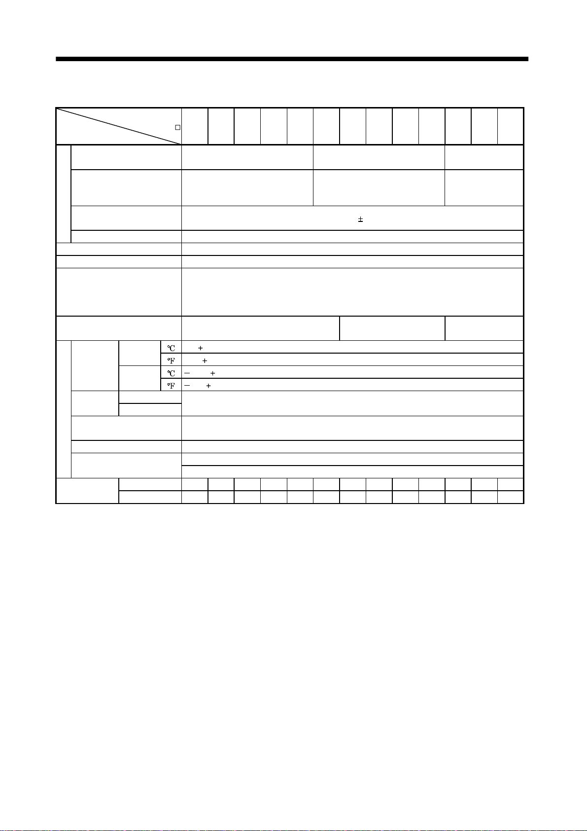
1.3 Servo amplifier standard specifications
Servo Amplifier
MR-J2S-
Item
Voltage/frequency
Permissible voltage
fluctuation
Permissible fr eq uency
Power supply
fluctuation
Power supply capacity Refer to Section 11.2
System Sine-wave PWM control, curr ent control system
Dynamic brake Built-in
Protective functions
Structure Self-cooled, open (I P00) Force-cooling, open (IP00 )
Ambient
temperature
Ambient
humidity
Ambient
Environment
Altitude Max. 1000m (3280ft) above sea level
Vibration
Weight
Operation
Storage
Operation
Storage
10B 20B 40B 60B 70B 100B 200B 350B 500B 700B 10B1 20B1 40B1
3-phase 200 to 230VAC, 50/60Hz or
1-phase 230VAC, 50/60Hz
3-phase 200 to 230VAC:170
to 253VAC
1-phase 230VAC: 207 to 253VAC
Overcurrent shut-off, regenerative overvoltage shut-off, overload shut-off (electronic thermal
relay), servo motor overheat protection, encoder fault protection, regenerative fault protection,
undervoltage, instantaneous power failure protection, overspeed protection, excessive error
protection
[ ]0 to 55 (non-freezing)
] 32 to 131 (non-freezing)
[
[ ] 20 to 65 (non-freezing)
[
] 4 to 149 (non-freezing)
90%RH or less ( non - condensing)
Indoors (no dir ect su nl i gh t )
Free from corrosive gas, flammable gas, oil mist, dust and dirt
5.9 [m/s2] or less
19.4 [ft/s
[kg] 0.7 0.7 1.1 1.1 1.7 1.7 2.0 2.0 4.9 7.2 0.7 0.7 1.1
[lb] 1.5 1.5 2.4 2.4 3.75 3.75 4.4 4.4 10.8 15.9 1.5 1.5 2.4
2
] or less
3-phase 200 to 230VAC, 50/60Hz
3-phase 170 to 253VAC
Within
5%
1-phase 100 to
120VAC 50/60Hz
1-phase
85 to 127VAC
Self-cooled,
open(IP00)
1 - 3
Page 19
1. FUNCTIONS AND CONFIGURATION
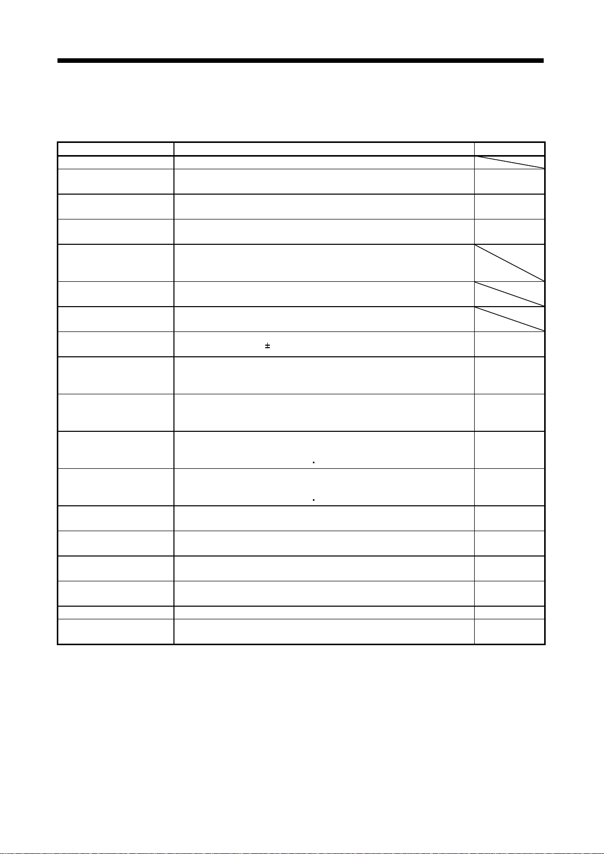
1.4 Function list
The following table lists the functions of this servo. For details of the functions, refer to the corresponding
chapters and sections.
Function Description Refer to
High-resolution encoder High-resolution encoder of 131072 pulses/rev is used as a servo motor encoder.
Absolute position detection
system
Adaptive vibration
suppression control
Low-pass filter
Machine analyzer function
Machine simulation
Gain search function
Slight vibration suppression
control
Auto tuning
Regenerative brake option
Brake unit
Return conv erter
Torque limit Servo motor-generated torque can be limited to any value.
Forced stop signal automaticONForced stop signal (EM1) can be automatically switched on internally to
Output signal (DO) forced
output
Test operati on mode
Analog monitor output Servo status is output in terms of voltage in real time. Parameter No. 22
Servo configurati on sof tw a re
Merely setting a home position once makes home position return unnecessary
at every power-on.
Servo amplifier detects mechanical resonance and sets filter characteristics
automatically to suppress mechanical vibration.
Suppresses high-frequency resonance which occurs as servo system response is
increased.
Analyzes the frequency characteristic of the mechanical system by simply
connecting a servo configuration software-installed personal computer and
servo amplifier.
Can simulate machine motions on a personal computer screen on the basis of
the machine analyzer results.
Personal computer changes gains automatically and searches for overshootfree gains in a short time.
Suppresses vibration of
Automatically adjusts the gain to optimum value if load applied to the servo
motor shaft varies. Higher in performance than MELSERVO-J2 series servo
amplifier.
Used when the built-in regenerative brake resistor of the servo amplifier does
not have sufficient regenerative capability for the regenerative power
generated.
Used when the regenerative brake option cannot provide enough regenerative
power.
Can be used with the MR-J2S-500B
Used when the regenerative brake option cannot provide enough regenerative
power.
Can be used with the MR-J2S-500B
invalidate it.
Output signal can be forced on/off independently of the servo status.
Use this function for output signal wiring check, etc.
Servo motor can be run from the operation section of the servo amplifier
without the start signal entered.
Using a personal computer, parameter setting, test operation, status display,
etc. can be performed.
1 pulse produced at a servo motor stop. Parameter No.24
MR-J2S-700B.
MR-J2S-700B.
Chapter 13
Section 7.3
Section 7.4
Chapter 6
Section 12.1.1
Section 12.1.2
Section 12.1.3
Parameters
No.10, 11
Parameter No.23
Section 4.4
(1) (e)
Section 4.4
Section 12.1.7
1 - 4
Page 20
1. FUNCTIONS AND CONFIGURATION
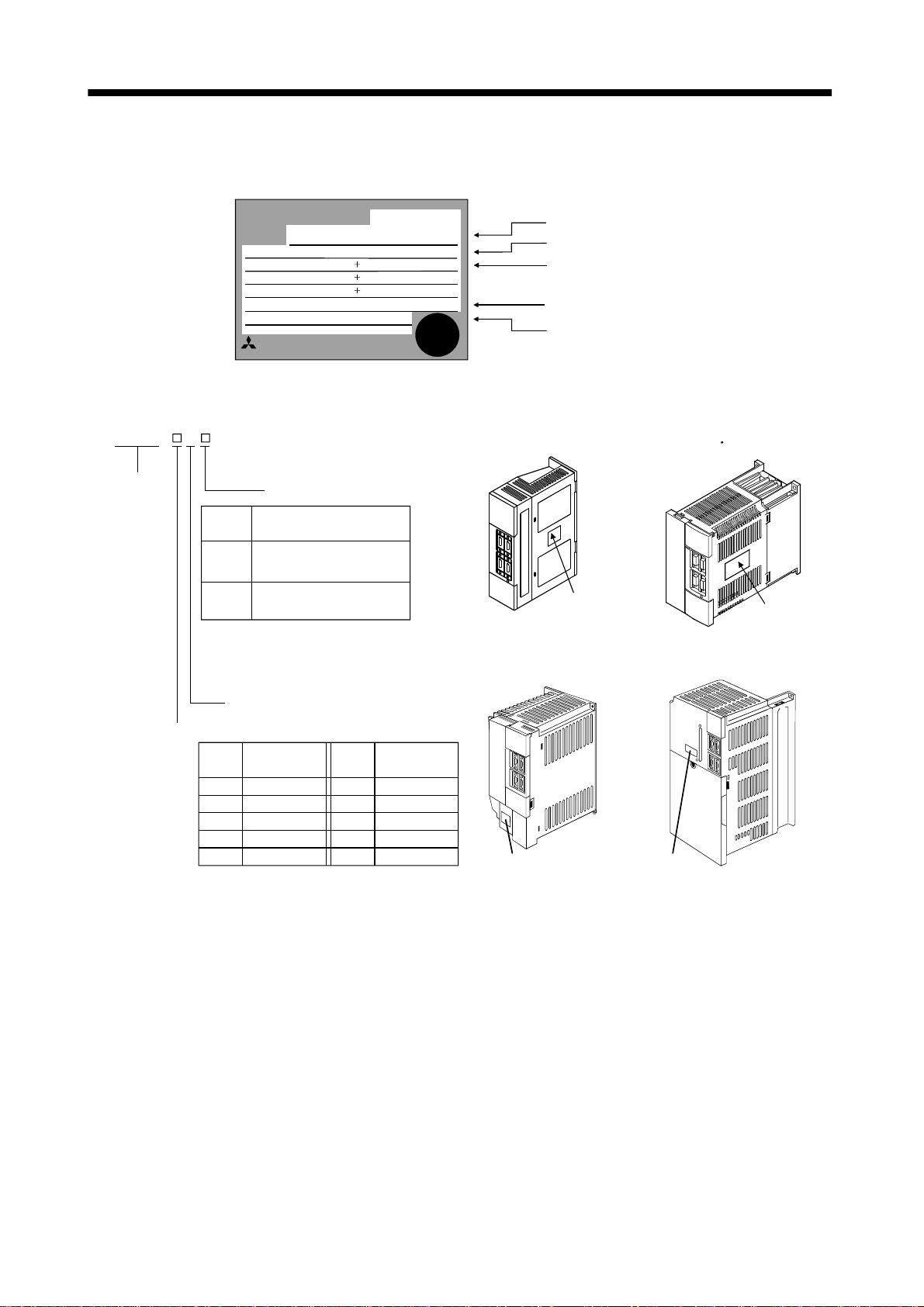
1.5 Model code definition (1) Rating plate
(2) Model
MR–J2S–
Series
MITSUBISHI
MODEL
POWER
MR-J2S-60B
POWER :
INPUT :
OUTPUT :
SERIAL :
MITSUBISHI ELECTRIC CORPORATION
MADE IN JAPAN
600W
3.2A 3PH 1PH200-230V 50Hz
5.5A 1PH 230V 50/60Hz
170V 0-360Hz 3.6A
TC3XXAAAAG52
B
Power Supply
Symbol
None
(Note1)
1
Power supply
3-phase 200 to 230VAC
(Note2) 1-phase 230VAC
1-phase 100V to 120VAC
Note:1. Not supplied to the servo amplifier
of MR-J2S-60B or more.
2. Not supplied to the servo amplifier
of MR-J2S-100B or more.
SSCNET compatible
Rated output
Symbol
Rated
output [W]
10010
20020
40040
60060
70070
AC SERVO
AC SERVO
3PH 1PH200-230V 60Hz
PASSED
Rated
Symbol
output [W]
1000100
2000200
3500350
5000500
7000700
Model
Capacity
Applicable power supply
Rated output current
Serial number
MR–J2S–100B or less
MR–J2S–200B 350B
Rating plate
MR-J2S-500B
MR-J2S-700B
Rating plate Rating plate
Rating plate
1 - 5
Page 21
1. FUNCTIONS AND CONFIGURATION
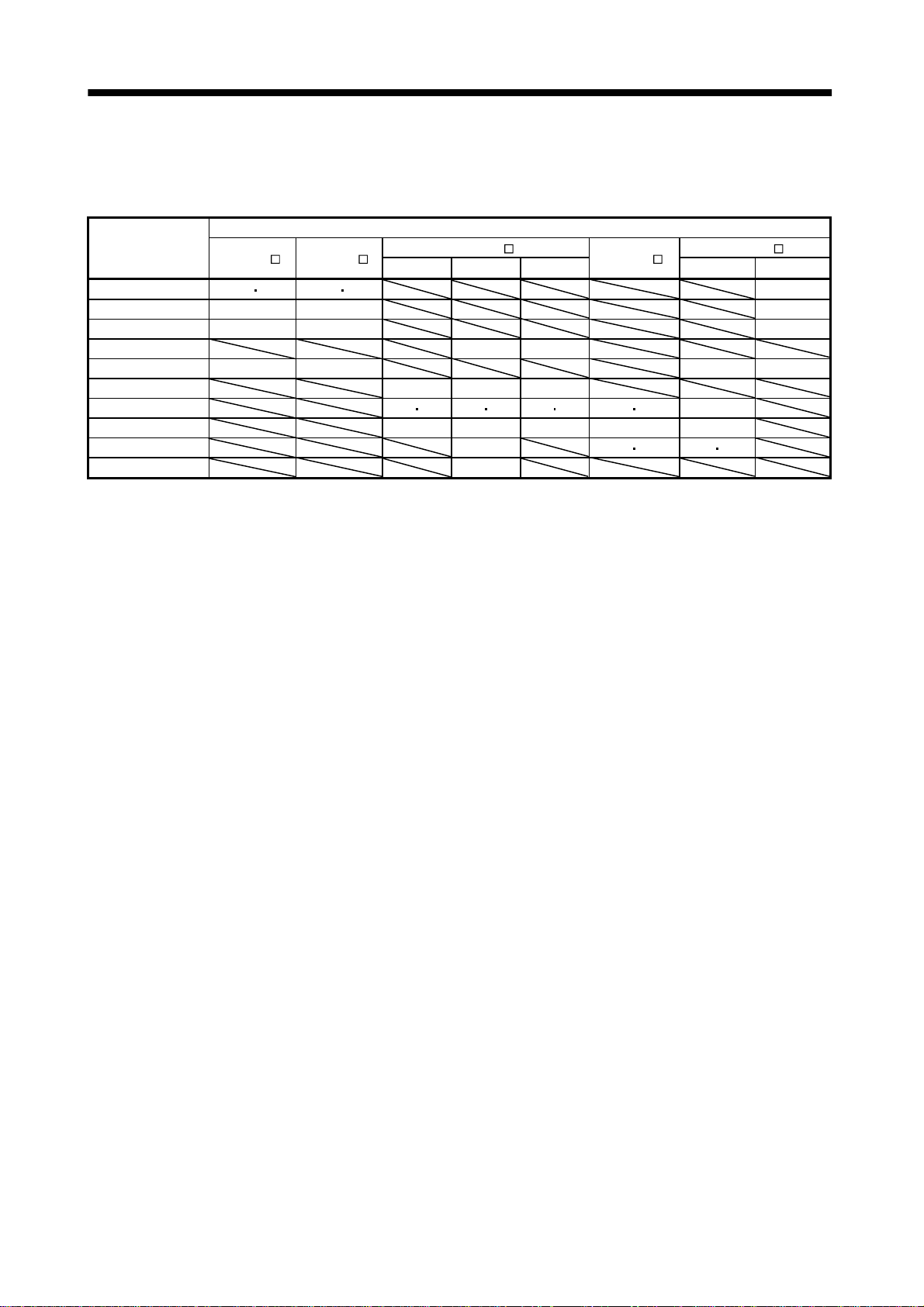
1.6 Combination with servo motor
The following table lists combina tion s of servo amplifie rs and se rvo mo tors. The same combina tions ap ply
to the models with electromagnetic brakes and the models with reduction gears.
Servo motors
Servo amplifier
MR-J2S-10B(1) 053 13 053 13 13
MR-J2S-20B(1) 23 23 23
MR-J2S-40B(1) 43 43 43
MR-J2S-60B 52 53
MR-J2S-70B (Note) 73 73 72 73
MR-J2S-100B 81 102 103
MR-J2S-200B 121 201 152 202 153 203 103 153 152
MR-J2S-350B 301 352 353 203 202
MR-J2S-500B 502 353 503 352 502
MR-J2S-700B 702
Note: The HC-K FS 7 3 ma y n ot be connected d epending on th e pr oduction time of the servo amplifi er . Please consult u s.
HC-KFS
HC-MFS
1000r/min 2000r/min 3000r/min
HC-SFS HC-UFS
HC-RFS
2000r/min 3000r/min
1 - 6
Page 22
1. FUNCTIONS AND CONFIGURATION
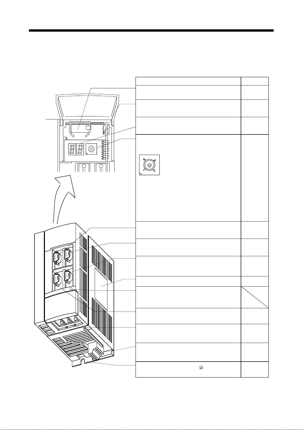
1.7 Structure
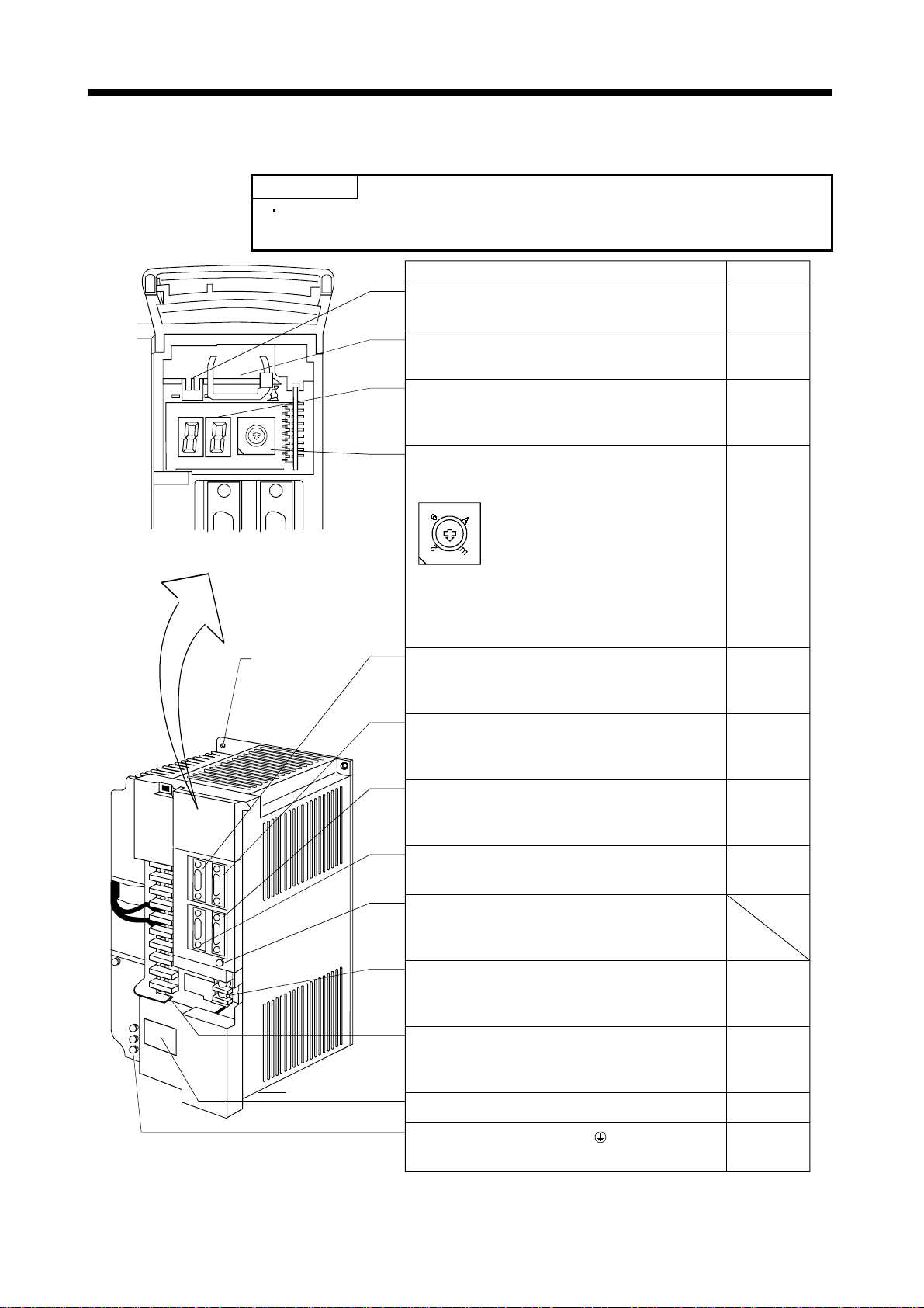
1.7.1 Parts identification (1) MR-J2S-100B or less
Name/Application
Battery h older
Contains the battery for absolute position data backup.
Refer to
Section13.3
Battery connector (CON1)
Used to connect the battery for absolute position data
Section13.3
backup.
Display
The two-digit, seven-segment LED shows the servo
Chapter4
status and alarm number.
Axis select switch (CS1)
8
9
7
A
6
B
5
C
4
3
D
2
E
1
F
0
CS1
5
4
3
C
D
F
1
0
servo amplifier.
Used to set the axis number of the
8
9
7
B
Section3.11
Bus cable connector (CN1A)
Used to connect the servo system controller or
Section3.2
preceding axis servo amplifier.
Bus cable connector (CN1B)
Used to connect the subsequent axis servo am plif ier
Section3.2
or termination connector (MR-A-TM).
Communication connector (CN3)
Used to connect a perso nal computer (RS-232C) o r
output analog monitor data.
Section3.2
Section12.1.4
Name plate
Charge lamp
Lit to indicate that the main circuit is charged. While
this lamp is lit, do not reconnect the cables.
Encoder connector ( C N2 )
Connector for connection of the servo motor encoder.
Main circuit terminal block (TE1)
Used to connect the input power supply and servo
motor.
Control circuit termi nal block (TE2 )
Used to connect the control circuit power supply and
regenerative brake option.
Protective earth (PE) terminal ( )
Ground terminal.
1 - 7
Section1.5
Section3.2
Section12.1.4
Section3.5.2
Section10.1
Section3.5.2
Section10.1
Section12.1.1
Section3.8
Section10.1
Page 23
1. FUNCTIONS AND CONFIGURATION
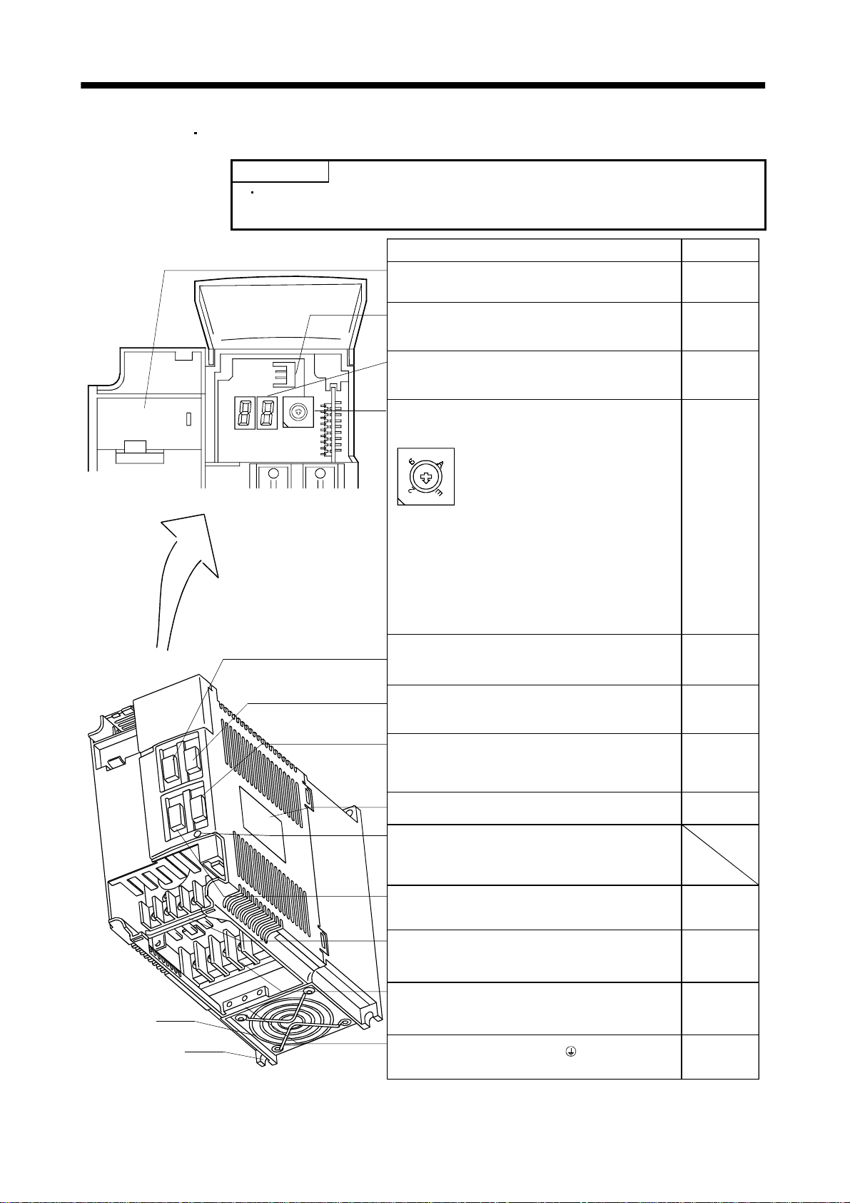
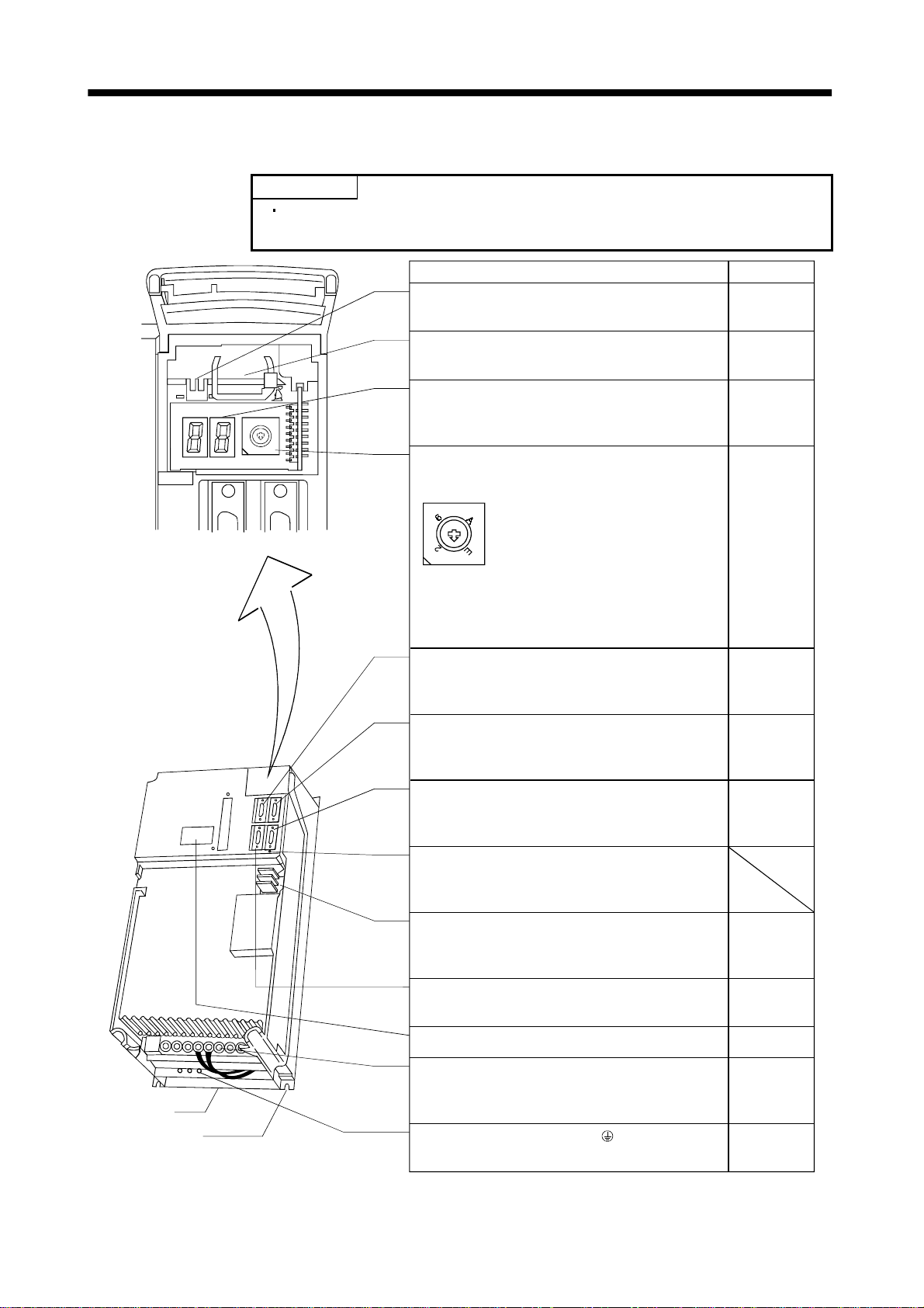
(2) MR-J2S-200B MR-J2S-350B
POINT
The servo amplifier is shown without the front cover. For removal of the
front cover, refer to Section 1.7.2.
Name/Application
Battery hol der
Contains the battery for absolute position data backup.
Refer to
Section13.3
Battery connector (CON1)
Used to connect the battery for absolute position data
Section13.3
backup.
Display
The two-digit, seven-segment LED shows the servo
8
9
7
A
6
B
5
C
4
3
D
2
E
1
F
0
status and alarm number.
Axis select switch (CS1)
Chapter4
CS1
5
4
3
1
the servo amplifier.
C
D
F
0
Used to set t he axis num b er of
8
9
7
B
Section3.11
Bus cable connect o r (CN 1 A )
Used to connect the servo system controller or
Section3.2
preceding axis servo amplifier.
Bus cable connector (CN1B)
Used to connect the subsequent axis servo amplifier
Section3.2
or termination connector (MR-A-TM).
Cooling fan
Installation notch
(4 places)
Communication connector (CN3)
Used to connect a personal computer (RS-232C) or
output analog monitor data.
Name plate
Charge lamp
Lit to indicate that the main circuit is charged. While
this lamp is lit, do not reconnect the cables.
Encoder conne cto r ( C N 2)
Connector for connection of the servo motor encoder.
Main circuit terminal block (TE1)
Used to connect the input power supply and servo
motor.
Control circuit ter m i na l b lock (TE2)
Used to connect the control circuit power supp ly a nd
regenerative brake option.
Protective earth (PE) terminal ( )
Ground terminal.
1 - 8
Section3.2
Section12.1.4
Section1.5
Section3.2
Section12.1.4
Section3.5.2
Section10.1
Section3.5.2
Section10.1
Section12.1.1
Section3.8
Section10.1
Page 24
1. FUNCTIONS AND CONFIGURATION
(3) MR-J2S-500B
POINT
The servo amplifier is shown without the front cover. For removal of the
front cover, refer to Section 1.7.2.
8
9
7
A
6
B
5
C
4
3
D
2
E
1
F
0
Installation notch
(4 places)
Name/Application
Battery connector (CON1)
Used to connect the battery for absolute position data
backup.
Battery h older
Contains the battery for absolute position data backup.
Display
The two-digit, seven-segment LED shows the servo
status and alarm number.
Axis select switch (CS1)
CS1
5
4
3
1
servo amplifier.
C
D
F
0
Used to set the axis number of the
8
9
7
B
Bus cable connector (CN1A)
Used to connect the servo system controller or
preceding axis servo amplifier.
Refer to
Section13.3
Section13.3
Chapter4
Section3.11
Section3.2
Cooling fan
Bus cable connector (CN1B)
Used to connect the subsequent axis servo am plif ier
or termination connector (MR-A-TM).
Communication connector (CN3)
Used to connect a perso nal computer (RS-232C) o r
output analog monitor data.
Encoder connector ( C N2 )
Connector for connection of the servo motor encoder.
Section3.2
Section3.2
Section12.1.4
Section3.2
Section12.1.4
Charge lamp
Lit to indicate that the main circuit is charged. While
this lamp is lit, do not reconnect the cables.
Control circuit termi nal block (TE2 )
Used to connect the control circuit power supply.
Section3.5.2
Section10.1
Section12.1.1
Main circuit terminal block (TE1)
Used to connect the input power supply, regen e rative
brake option and servo motor.
Section3.5.2
Section10.1
Name plate Section1.5
Protective earth (PE) terminal ( )
Ground terminal.
Section3.8
Section10.1
1 - 9
Page 25
1. FUNCTIONS AND CONFIGURATION
(4) MR-J2S-700B
POINT
The servo amplifier is shown without the front cover. For removal of the
front cover, refer to Section 1.7.2.
Name/Application
Refer to
Battery connector (CON1)
Used to connect the battery for absolute position data
Section13.3
backup.
Battery h older
Contains the battery for absolute position data backup.
Section13.3
Display
8
9
7
A
6
B
5
C
4
3
D
2
E
1
F
0
The two-digit, seven-segment LED shows the servo
status and alarm number.
Chapter4
Axis select switch (CS1)
CS1
5
4
3
1
C
D
F
0
servo amplifier.
Section3.11
Used to set the axis number of the
8
9
7
B
Bus cable connector (CN1A)
Used to connect the servo system controller or
preceding axis servo amplifier.
Section3.2
Cooling fan
Installation notch
(4 places)
Bus cable connector (CN1B)
Used to c onnect th e subsequ e nt axis servo ampl i fier
or termination connector (MR-A-TM).
Communication connector (CN3)
Used to connect a personal computer (RS-232C) or
output analog monitor data.
Charge lamp
Lit to indicate that the main circuit is charged. While
this lamp is lit, do not reconnect the cables.
Control circuit termi nal block (TE2 )
Used to connect the control circuit power supply.
Encoder connector ( C N2 )
Connector for connection of the servo motor encoder.
Name plate
Main circuit terminal block (TE1)
Used to connect the input power supply, reg ene rative
brake option and servo motor.
Protective earth (PE) terminal ( )
Ground terminal.
Section3.2
Section3.2
Section12.1.4
Section3.5.2
Section10.1
Section12.1.1
Section3.2
Section12.1.4
Section1.5
Section3.5.2
Section10.1
Section3.8
Section10.1
1 - 10
Page 26
1. FUNCTIONS AND CONFIGURATION
1.7.2 Removal and reinstallation of the front cover
CAUTION
To avoid the risk of an electric s hock, do not ope n the front co ver while power is
on.
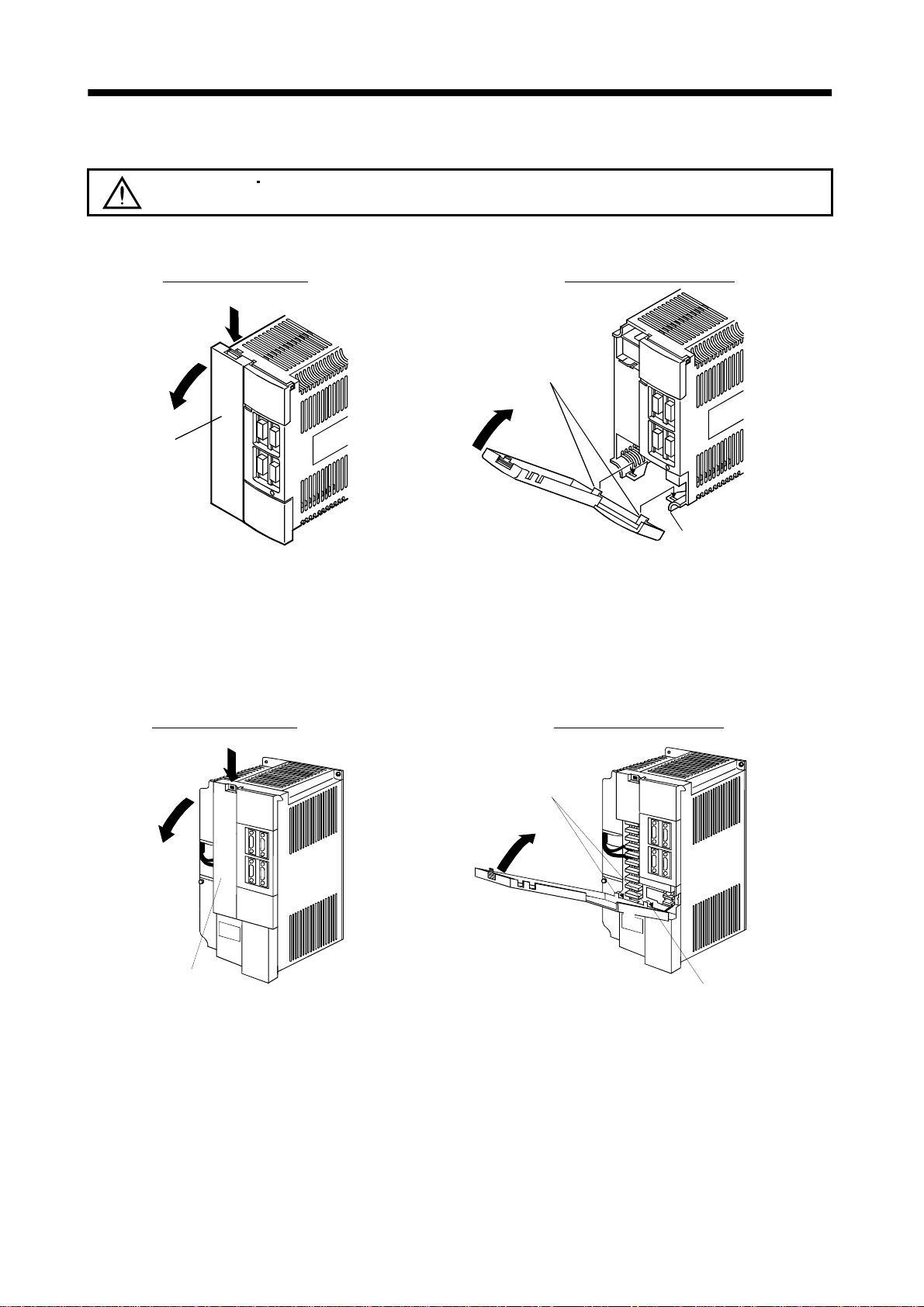
(1) For MR-J2S-200B or more
Removal of the front cover
1)
2)
Front cove r
1) Hold down the removing knob.
2) Pull the front cover toward you.
Reinstallation of the front cover
Front cover hook
(2 places)
2)
1)
Front cove r socket
(2 places)
1) Insert the front cover hooks into the front cover sockets of
the servo amplifier.
2) Press the front cover against the servo amplifier until the
removing knob clicks.
(2) For MR-J2S-500B
Removal of the front cover
2)
Front cover
1) Hold down the removing knob.
2) Pull the front cover toward you.
Reinstallation of the front cover
1)
Front cover hook
(2 places)
2)
1)
Front cover socket
(2 places)
1) Insert the front cover hooks into the front cover sockets of
the servo amplifier.
2) Press the front cover against the servo amplifier until the
removing knob clicks.
1 - 11
Page 27
1. FUNCTIONS AND CONFIGURATION
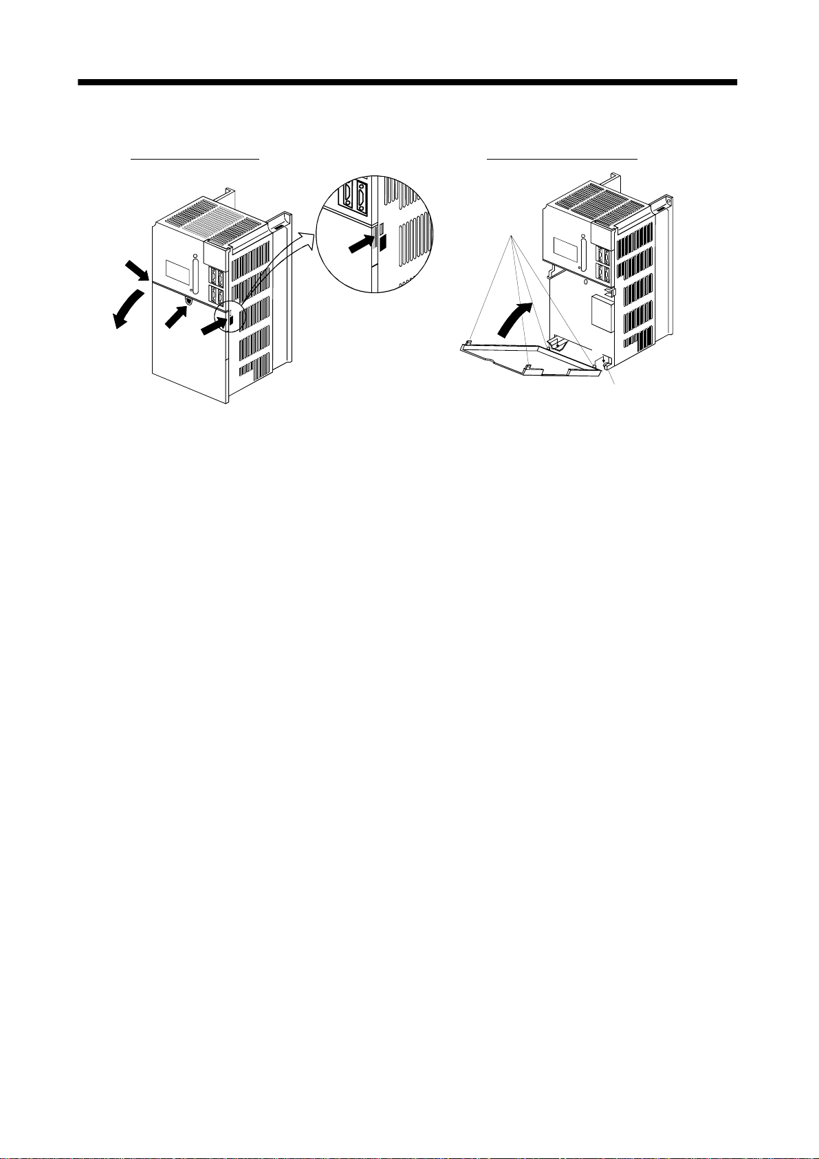
(3) For MR-J2S-700B
Removal of the front cover
Reinstallation of the front cover
Front cove r
hook
(2 places)
B)
2)
1)
A)
1) Push the removing knob A) or B), and put you
finger into the front hole of the front cover.
2) Pull the front cover toward you.
A)
2)
1)
Front cove r socket
(2 places)
1) Insert the two front cover hooks at the bottom into the
sockets of the servo amplifier.
2) Press the front cover against the servo amplifier until the
removing knob clicks.
1 - 12
Page 28
1. FUNCTIONS AND CONFIGURATION
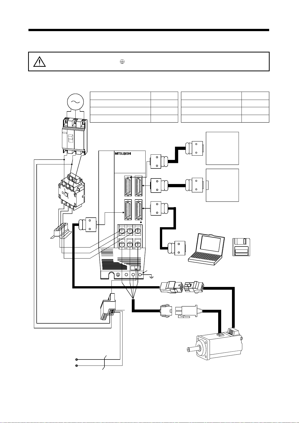
1.8 Servo system with auxiliar y equipm ent To prevent an electric shock, always connect the protective earth (PE) terminal
WARNING
(terminal m ar ked
box.
(1) MR-J2S-100B or less
(a) For 3-phas e 200V t o 230V A C or 1 -p hase 23 0V A C
(Note2)
3-phase 200V
to 230VAC power
supply or
1-phase 230VAC
power supply
No-fuse breaker
(NFB) or fuse
Options and auxiliary equipment
No-fuse breaker
Magnetic contactor
Servo configuration so ft ware
Servo amplifier
) of the servo amplifier to the prot ecti ve earth (P E) of the contr ol
Refer to
Section 12.2.2
Section 12.2.2
Section 12.1.7
Options and auxiliary equipment
Regenerative brake option
Cables
Power factor improving reactor Section 12.2.3
Servo system
controller
or
preceding axis
servo amplifier
Refer to
Section 12.1.1
Section 12.2.1
Magnetic
contactor
(MC)
Power
factor
improving
reactor
(FR-BAL)
Control circuit terminal block
To CN2
L1
2
L
L
3
CHARGE
UV
D
To CN1A
To CN1B
To CN3
W
Protective earth(PE) terminal
Subsequent axis
servo amplifier
CN1A
or
Termination
connector
Personal
computer
(Note1)
Encoder cable
(Note1)
Power supply lead
Servo configuration
software
MRZJW3-SETUP121E
L21
11
L
Regenerative brake
option
Note: 1. The HC-SFS, HC-RFS series have cannon connectors.
2. A 1-phase 230VAC power supply may be used with the servo amplifier of MR-J2S-70B or less. Connect the power supply to
L
and L2 terminals and leave L3 open.
1
P
Servo motor
C
1 - 13
Page 29
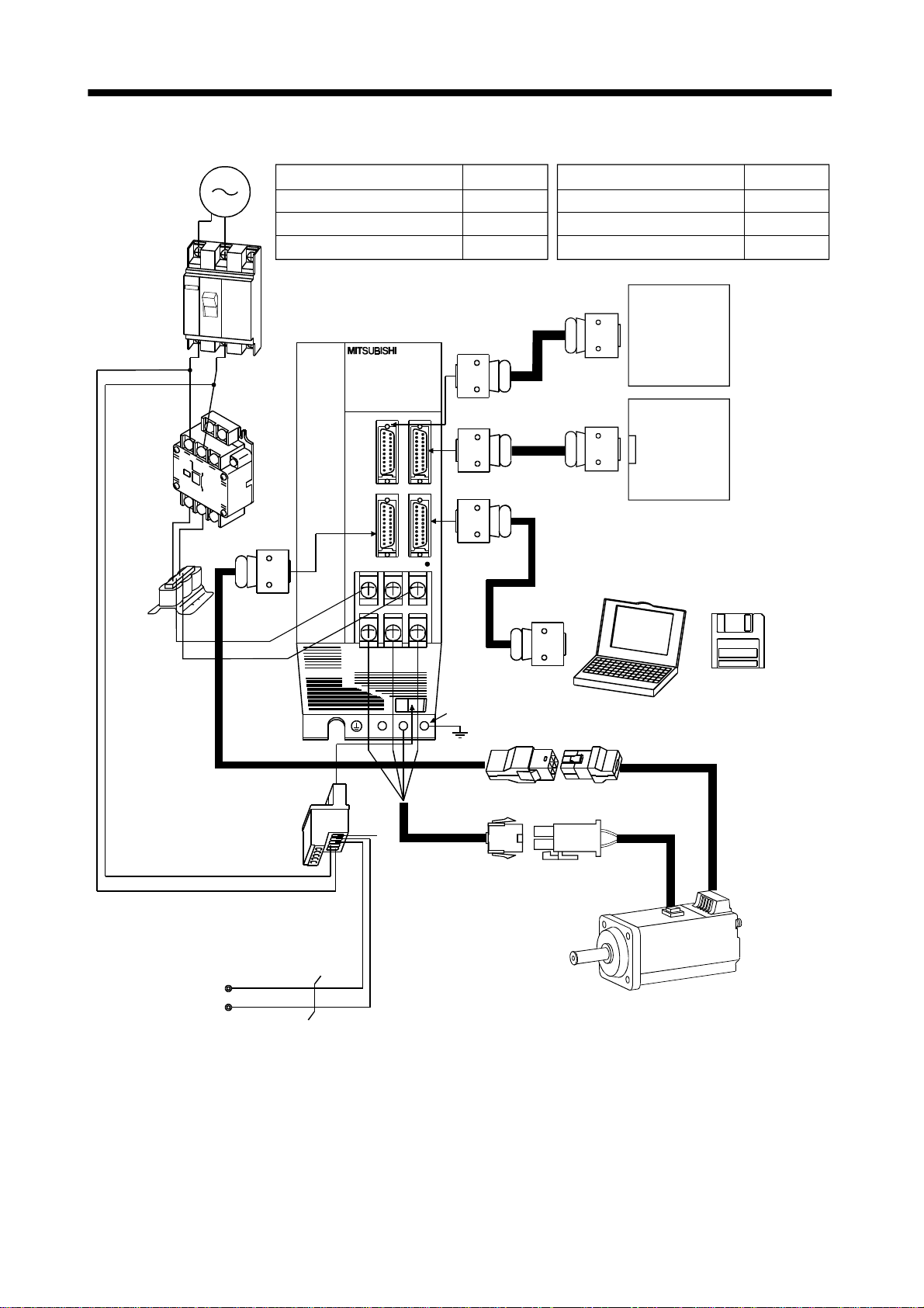
1. FUNCTIONS AND CONFIGURATION
,
(b) For 1-phas e 10 0V t o 120V A C
1-phase 100VAC
power supply
No-fuse breaker
(NFB) or fuse
Magnetic
contactor
(MC)
Power
factor
improving
reactor
(FR-BAL)
Options and auxiliary equipment
No-fuse breaker
Magnetic contactor
Servo configuration so ft ware
Servo amplifier
To CN2
L1
L
2
UV
CHARGE
W
Refer to
Section 12.2.2
Section 12.2.2
Section 12.1.7
To CN1A
To CN1B
To CN3
Options and auxiliary equipment
Regenerative brake option
Refer to
Section 12.1.1
Cables Section 12.2.1
Power factor improving reactor Section 12.2.3
Servo system
controller
or
preceding axis
servo amplifier
Subsequent axis
servo amplifier
CN1A
or
Termination
connector
Personal
computer
Servo configuration
software
MRZJW3-SETUP121E
Control circuit terminal block
L
21
L
11
Regenerative brake
option
Note: The HC-SFS
Protective earth(PE) terminal
(Note)
Encoder cable
(Note)
Power supply lead
D
P
Servo motor
C
HC-RFS series have cannon connectors.
1 - 14
Page 30
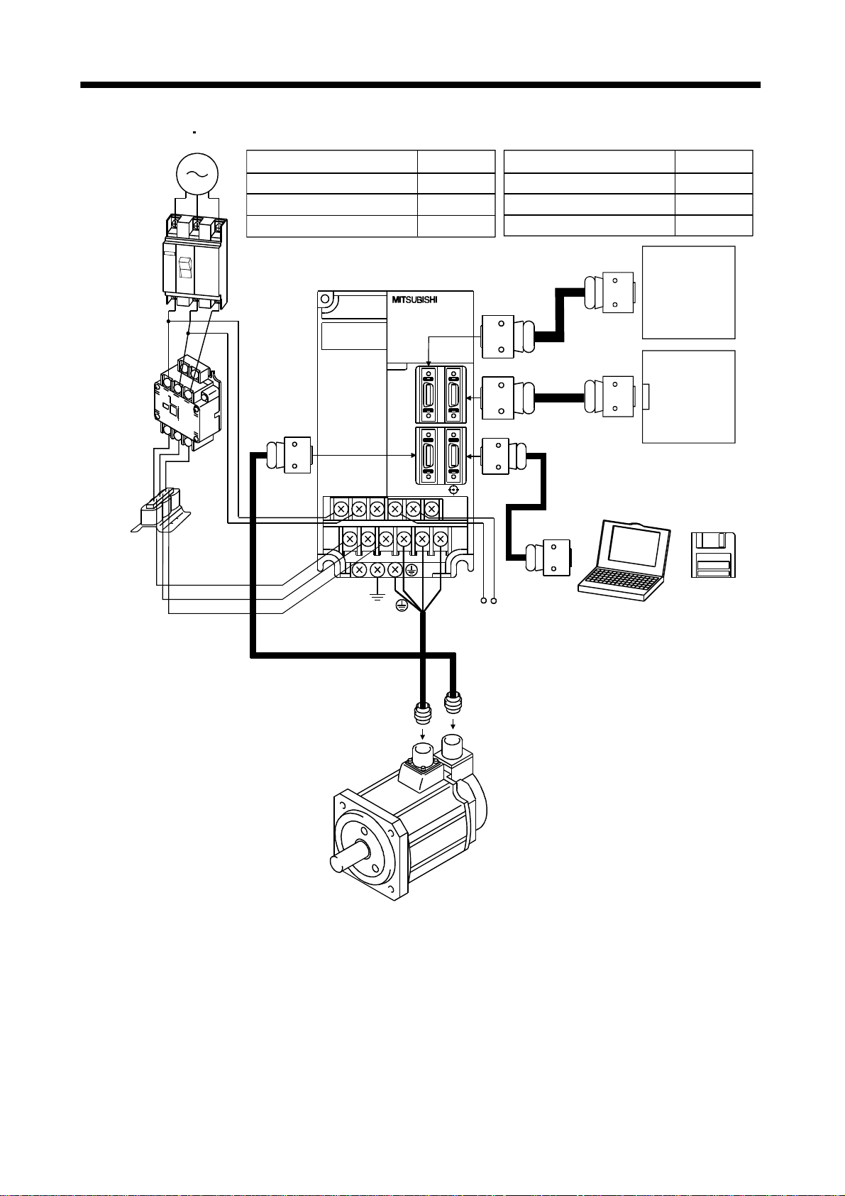
1. FUNCTIONS AND CONFIGURATION
(2) MR-J2S-200B MR-J2S-350B
3-phase 200V
to 230VAC
power supply
No-fuse
breaker
(NFB) or
fuse
Magnetic
contactor
(MC)
Power facto r
improving
reactor
(FA-BAL)
Options and auxiliary equipment
No-fuse breaker
Magnetic contactor
Servo configuration so ft ware
Servo amplifier
To CN2
L
11
L
21
Refer to
Section 12.2.2
Section 12.2.2
Section 12.1.7
Options and auxiliary equipment Refer to
Regenerative brake option
Section 12.1.1
Cables Section 12.2.1
Power factor improving reactor Section 12.2.3
Servo system
controller
or
Preceding axis
servo amplifier
To CN1A
Subsequent axis
servo amplifier
CN1A
or
To CN1B
Termination
connector
Servo
To CN3
Personal
computer
configuration
software
MRZJW3SETUP121E
L1
L
L
U
2
3
V
PC
W
Regenerative brake option
1 - 15
Page 31
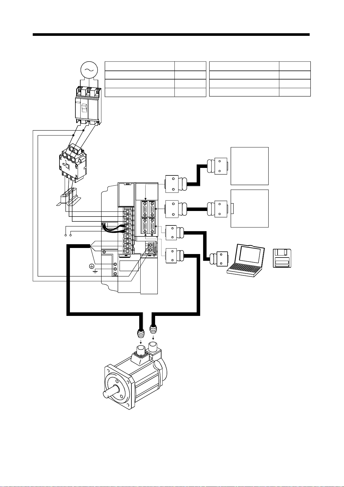
1. FUNCTIONS AND CONFIGURATION
(3) MR-J2S-500B
3-phase 200V
to 230VAC
power supply
No-fuse
breaker
(NFB) or
fuse
Options and auxiliary equipment
No-fuse breaker
Magnetic contactor
Servo configura tion software
Refer to
Section 12.2.2
Section 12.2.2
Section 12.1.7
Options and auxiliary equipment Refer to
Regenerative brake option
Section 12.1.1
Cables Section 12.2.1
Power factor improving reactor Section 12.2.3
Magnetic
contactor
(MC)
Power
factor
improving
reactor
(FA-BAL)
C
Regenerative brake
option
L
11
21
L
Servo system
controller
or
Preceding axis
Servo amplifier
To CN1A
1
L
L
2
L
3
To CN1B
servo amplifier
Subsequent axis
servo amplifier
CN1A
or
Termination
connector
Servo
configuration
P
U
V
To CN3
Personal
computer
W
software
MRZJW3SETUP121E
To CN2
1 - 16
Page 32

1. FUNCTIONS AND CONFIGURATION
(4) MR-J2S-700B
3-phase 200V
to 230VAC
power supply
No-fuse
breaker
(NFB) or
fuse
Magnetic
contactor
(MC)
Power
factor
improving
reactor
(FA-BAL)
Options and auxiliary equipment
No-fuse breaker
Magnetic contactor
Servo configuration software
Servo amplifier
L
11
21
L
L
3
L
2
1
L
Refer to
Section 12.2.2
Section 12.2.2
Section 12.1.7
To CN1A
To CN1B
To CN3
To CN2
U
V
W
Options and auxiliary equipment Refer to
Regenerative brake option
Section 12.1.1
Cables Section 12.2.1
Power factor improving reactor S ection 12.2.3
Servo syste m
controller
or
Preceding axis
servo amplifier
Subsequent axis
servo amplifier
CN1A
or
Termination
connector
Servo
configuration
Personal
computer
software
MRZJW3SETUP121E
C
P
Regene rative br ake
option
1 - 17
Page 33

1. FUNCTIONS AND CONFIGURATION
MEMO
1 - 18
Page 34

2. INSTALLATION
2. INSTALLATION
CAUTION
Stacking in excess of the limited number of products is not allowed.
Install the equipment to incombustibles. Installing them directly or close to
combustibles will led to a fire.
Install the equipment in a load-bearing place in accordance with this Instruction
Manual.
Do not get on or put heavy load on the equipment to prevent injury.
Use the equipment within the specified environmental condition range.
Provide an adequate protection to prevent screws, metallic detritus and other
conductive matter or oil and other combustible matter from entering the servo
amplifier.
Do not block the inta ke /e xhau st po rts o f th e se rv o ampl ifier. Otherwise, a fa ul t may
occur.
Do not subject the servo amplifier to drop impact or shock loads as they are
precision equipment.
Do not install or operate a faulty servo amplifier.
When the product has been stored for an extended period of time, consult
Mitsubishi.
2.1 Environmental con dit ions
Environment Conditions
Ambient
temperature
Ambient
humidity
Ambience
Altitude Max. 1000m (3280 ft) above sea level
Vibration
Operation
Storage
Operation
Storage
[ ]0 to 55 (non-freezing)
[
] 32 to 131 (non-freezing)
[ ] 20 to 65 (non-freezing)
] 4 to 149 (non-freezing)
[
90%RH or less (non-condensing)
Indoors (no direct sunlight)
Free from corrosive gas, flammable gas, oil mist, dust and dirt
[m/s2] 5.9 [m/s2] or less
2
] 19.4 [ft/s2] or less
[ft/s
2 - 1
Page 35

2. INSTALLATION
2.2 Installation direction and clearances The equipment mus t be installe d in the specif ied direc tion. Other wise, a fau lt may
CAUTION
(1) Installation of one servo amplifier
10mm
(0.4 in.)
or more
occur.
Leave specified clearances between the servo amplifier and control box inside
walls or other equipment.
Control box Control box
40mm
(1.6 in.)
or more
Servo amplifier
10mm
(0.4 in.)
or more
Wiring clearance
70mm
(2.8 in.)
Top
40mm
(1.6 in.)
or more
Bottom
2 - 2
Page 36

2. INSTALLATION
(2) Installation of two or more servo amplifiers
Leave a large clearance between the top of the servo amplifier and the internal surface of the control
box, and install a fan to prevent the internal temperature of the control box from exceeding the
environmental conditions.
Control box
100mm
(4.0 in.)
or more
Servo
amplifier
10mm
(0.4 in.)
or more
30mm
(1.2 in.)
or more
40mm
(1.6 in.)
or more
30mm
(1.2 in.)
or more
(3) Others
When using heat generating equipment such as the regenerative brake option, install them with full
consideration of heat generation so that the servo amplifier is not affected.
Install the servo amplifier on a perpendicular wall in the correct vertical direction.
2.3 Keep out foreign materials
(1) When installin g the unit in a control box, prevent drill ch ips and wire fragmen ts from entering the
servo amplifier.
(2) Prevent oil, water, metallic dust, etc. from entering the servo amplifier through openings in the control
box or a fan installed on the ceiling.
(3) When insta lling the co ntrol box in a place whe re there are much toxic g as, dirt and dust, conduct an
air purge (force clean air into the contro l box from outside to make the internal pressure higher than
the external pressure) to prevent such materials from entering the control box.
2 - 3
Page 37

2. INSTALLATION
2.4 Cable stress
(1) The way of clamping the cable must be fully examined so that flexing stress and cable's own weight
stress are not applied to the cable connection.
(2) In any application where the servo motor moves, the cables should be free from excessive stress. For
use in any application where the servo motor moves run the cables so that their flexing portions fall
within the optional encoder cable range. Fix the encoder cable and power cable of the servo motor.
(3) Avoid any probability that the cable sheath might be cut by sharp chips, rubbed by a machine corner
or stamped by workers or vehicles.
(4) For installation on a machine where the servo motor will move, the flexing radius should be made as
large as possible. Refer to section 11.4 for the flexing life.
2 - 4
Page 38
3. SIGNALS AND WIRING
3. SIGNALS AND WIRING
Any person who is involved in wiring should be fully competent to do the work.
Before starting wiring, make sure that the voltage is safe in the tester more than 10
minutes after power-off. Otherwise, you may get an electric shock.
WARNING
CAUTION
Ground the servo amplifier and the servo motor securely.
Do not attempt to wire the servo amplifier and servo motor until they have been
installed. Otherwise, you may get an electric shock.
The cables should not be damaged, stressed excessively, loaded heavily, or
pinched. Otherwise, you may get an electric shock.
Wire the equipment correctly and securely. Otherwise, the servo motor may
misoperate, resulting in injury.
Connect cables to correct terminals to prevent a burst, fault, etc.
Ensure that polarity ( , ) is correct. Otherwise, a burst, damage, etc. may occur.
The surge absorbing diode installed to the DC relay designed for control output
should be fitted in the specified direction. Otherwise, the signal is not output due to
a fault, disabling the forced stop and other protective circuits.
Servo
Amplifier
COM
(24VDC)
Control
output
signal
RA
Servo amplifier
COM
(DC24V)
Control output
signal
RA
Use a noise filter, etc. to minimize the influence of electromagnetic interference,
which may be given to electronic equipment used near the servo amplifier.
Do not install a power capacitor, surge suppressor or radio noise filter (FR-BIF
option) with the power line of the servo motor.
When using the regenerative brake resistor, switch power off with the alarm signal.
Otherwise, a transistor fault or the like may overheat the regenerative brake
resistor, causing a fire.
Do not modify the equipment.
POINT
CN1A, CN1B, CN2 and CN3 have the same shape. Wrong connection of
the connectors will lead to a failure. Connect them correctly.
3 - 1
Page 39

3. SIGNALS AND WIRING
3.1 Connection example of control signal system
POINT
Refer to Section 3.5 for the connection of the power supply system and to
Section 3.6 for connection with the servo motor.
(Note 9)
Servo configuration
software
Servo system controller
A1SD75M(AD75M)
Cable clamp
(Option)
or
Motion
controller
Cable clamp
(Option)
(Note 10, 14) Bus cable
MR-J2HBUS M-A
(Note 10, 14) Bus cable
MR-J2HBUS M-A
(Note 4)
Personal computer
(Option)
(Option)
15m(49.2ft)
or less
Servo amplifier
(Note 5)
CN3
6
16
7
17
8
18
Plate
CN3
(Note 5,8)
CN3
20
3
4
1
14
11
Plate
(Note 5)
CN1A
(Note 5)
CN1B
CN1A
CN1B
13
5
10
CS1
Setting:0
MR-J2S-B
(2 axis)
CS1
Setting 1
LA
LAR
LB
LBR
LZ
LZR
SD
2m(6.56ft) or less
EM1
SG
MO1
LG
MO2
LG
SD
MBR
COM
VDD
(Note 1)
(Note 11)
Encoder A-phase pulse
(differential line driver)
Encoder B-phase pulse
(differential line driver)
Encoder Z-phase pulse
(differential line driver)
(Note 3,4,7)
Forced stop
A
A
RA1
Always connect.
Monitor output
10k
Max. 1mA
Reading in
10k
both directions
(Note 2,6)
Magnetic brake
interlock
(Note 10, 14)
Bus cable
(Option)
(Note 13)
MR-A-TM
3 - 2
MR-J2S-B
CN1A
CN1B
Setting 2
MR-J2S-B
CN1A
CN1B
Setting: n
(3 axis)
CS1
(n axis)
CS1
(Note 11)
(Note 11)
(Note 12)
1
n
1 to 8
Page 40

3. SIGNALS AND WIRING
Note 1. To prevent an electric shock, always connect the protective earth (PE) terminal (terminal marked
) of the servo amplifier to the protective earth (PE) of the control box.
2. Connect the diode in the correct direction. If it is connected reversely, the servo amplifier will be
faulty and will not output signals, disabling the forced stop and other protective circuits.
3. If the controller does not have an emergency stop function, always install a forced stop switch
(Normally closed).
4. When a personal computer is connected for use of the test operation mode, always use the
maintenance junction card (MR-J2CN3TM) to enable the use of the forced stop (EM1). (Refer to
section 12.1.5)
5. CN1A, CN1B, CN2 and CN3 hav e th e same sh ap e . Wron g co nn ectio n o f the con ne ctor s will le ad
to a fault.
6. The sum of currents that flow in the external relays should be 80mA max.
7. When starting operation, always connect the forced stop signal (EM1) and SG. (Normally closed
contacts) By setting “0001” in parameter No.23, the forced stop signal can be made invalid.
8. When connecting the personal computer together with monitor outputs 1, 2, use the
maintenance junction card (MR-J2CN3TM). (Refer to Section 12.1.3.)
9. Use MRZJW3-SETUP121E.
10. Use the bus cable at the overall distance of 30m(98.4ft) or less. In addition, to improve noise
immunity, it is recommended to use a cable clamp and data line filters (three or four filters
connected in series) near the connector outlet.
11. The wiring of the second and subsequent axes is omitted.
12. Up to eight axe s (n
servo amplifier may be connected on the same bus.
13. Always insert the terminat ion connector (MR-A- TM) into CN1B of the servo amplifier lo cated
at the termination.
14. The bus cable used with the SSCNET depends on the preceding or subsequent controller or
servo amplifier connected. Refer to the following table and choose the bus cable.
1 to 8) may be conn ected. The MR-J2S- B/MR-J2-03B5/MR H-BN
MR-J2S- B MR-J2-03B5 MR-H BN
A1SD75M(AD75M) MR-J2HBUS M-A MR-HBUS M
Motion controlle r MR-J2HBUS M-A MR-HBUS M
MR-J2S- B
MR-J2- B MR-J2-03B5
MR-H BN MR-J B MR-J2HBUS M-A MR-HBUS M
MR-J2HBUS
M MR-J2HBUS M-A
3 - 3
Page 41

3. SIGNALS AND WIRING
3.2 I/O signals
3.2.1 Connectors and signal arrangements POINT
The connector pin-outs shown above are viewed from the cable connector
wiring section side.
(1) Signal arrangement
CN1A CN1B
1
2
LG LG
RD RD*
3
4
TD TD*
5
6
LG LG
7
8
EMG
9
10
BT
CN2 CN3
1
2
LG
LG
3
4
5
6
MD
7
8
MR
9
10
BAT
12
14
16
18
20
12
LG
14
16
MDR
18
P5
20
P5
11
13
15
17
EMG*
19
11
LG
13
15
17
MRR
19
P5
MITSUBISHI
MELSERVO-J2
The connector frames are
connected with the PE (earth)
terminal inside the servo amplifier.
1
2
LG LG
RD RD*
3
4
TD TD*
5
6
LG LG
7
8
EMG
9
10
BT
1
2
LG
RXD
3
4
SG
MO1
5
6
COM
LA
7
8
LB
9
10
VDD
12
14
16
18
20
12
TXD
14
MO2
16
LAR
18
LZRLZ
20
EM1
11
13
15
17
EMG*
19
11
LG
13
MBR
15
17
LBR
19
3 - 4
Page 42

3. SIGNALS AND WIRING
3.2.2 Signal expla na ti on s
For the I/O interfaces (symbols in I/O column in the table), refer to Section 3.4.2.
(1) Connector applications
Connector Name Function/Application
CN1A Connector for bus cable from preceding axis.
CN1B Connector for bus cable to next axis
CN2 Encoder connector Used for connection with the servo motor encoder.
CN3
Communication connector
(I/O signal connector)
(2) I/O signals
(a) Input signal
Signal Symbol
Forced stop EM1
Connector Pin
No.
CN3
20
Disconnect EM1-SG to bring the servo motor to a forced stop
state, in which the servo is switched off and the dynamic
brake is operated.
In the forced stop state, connect EM1-SG to reset that state.
Used for connection with the controller or preceding-axis
servo amplifier.
Used for connection with the next-axis servo amplifier or
for connection of the terminati on co n nector.
Used for connection w i th the personal computer.
Serves as an I/O signal connector when the personal
computer is not used.
Function/Application I/O Division
DI-1
(b) Output signals
MBR
LA
LAR
LB
LBR
LZ
LZR
Connector Pin
No.
CN3
13
CN3
6
CN3
16
CN3
7
CN3
17
CN3
8
CN3
18
CN3
4
CN3
14
Function/Application I/O Division
In the servo-off or alarm status, MBR-SG are disconnected.
When an alarm occurs, they are disconnected, independently
of the base circuit status.
Outputs pulses per servo motor revolution set in parameter
No.38 in the differential li ne driver system. In CCW rotation
of the servo motor, the encoder B-phase pulse lags the
encoder A-phase pulse by a phase angle of
The zero-phase signal of the encoder is output in the
differential line driver system.
Used to output the data set in parameter No.22 to across
MO1-LG in terms of voltage. Resolution 10 bits
Used to output the data set in parameter No.22 to across
MO2-LG in terms of voltage. Resolution 10 bits
/2.
Signal Symbol
Electromagnetic brake
interlock
Encoder A-phase pulse
(Differential line driver)
Encoder B-phase pulse
(Differential line driver)
Encoder Z-phase pulse
(Differential line driver)
Analog monitor 1 MO1
Analog monitor 2 MO2
(c) Power supply
VDD
COM
SG
Connector Pin
No.
CN3
10
CN3
5
CN3
3
CN3
1
11
Function/Application
Driver power output terminal for digital interface.
Used to output
Permissible current: 80mA
Driver power input terminal for digital interface.
Used to input 24VDC (200mA or more) for input interface.
Connect with VDD.
Common terminal to VDD and COM. Pins are connected internally.
Separated from LG.
Common termin al to MO1 an d MO2.
24V 10% to across VDD-COM. Connect with COM.
Signal Symbol
Internal power output
for interface
Power input for digital
interface
Common for digital
interface
Control common LG
Shield SD Plate Connect the external conductor of the shield cable.
DO-1
DO-2
DO-2
Analog
output
Analog
output
3 - 5
Page 43
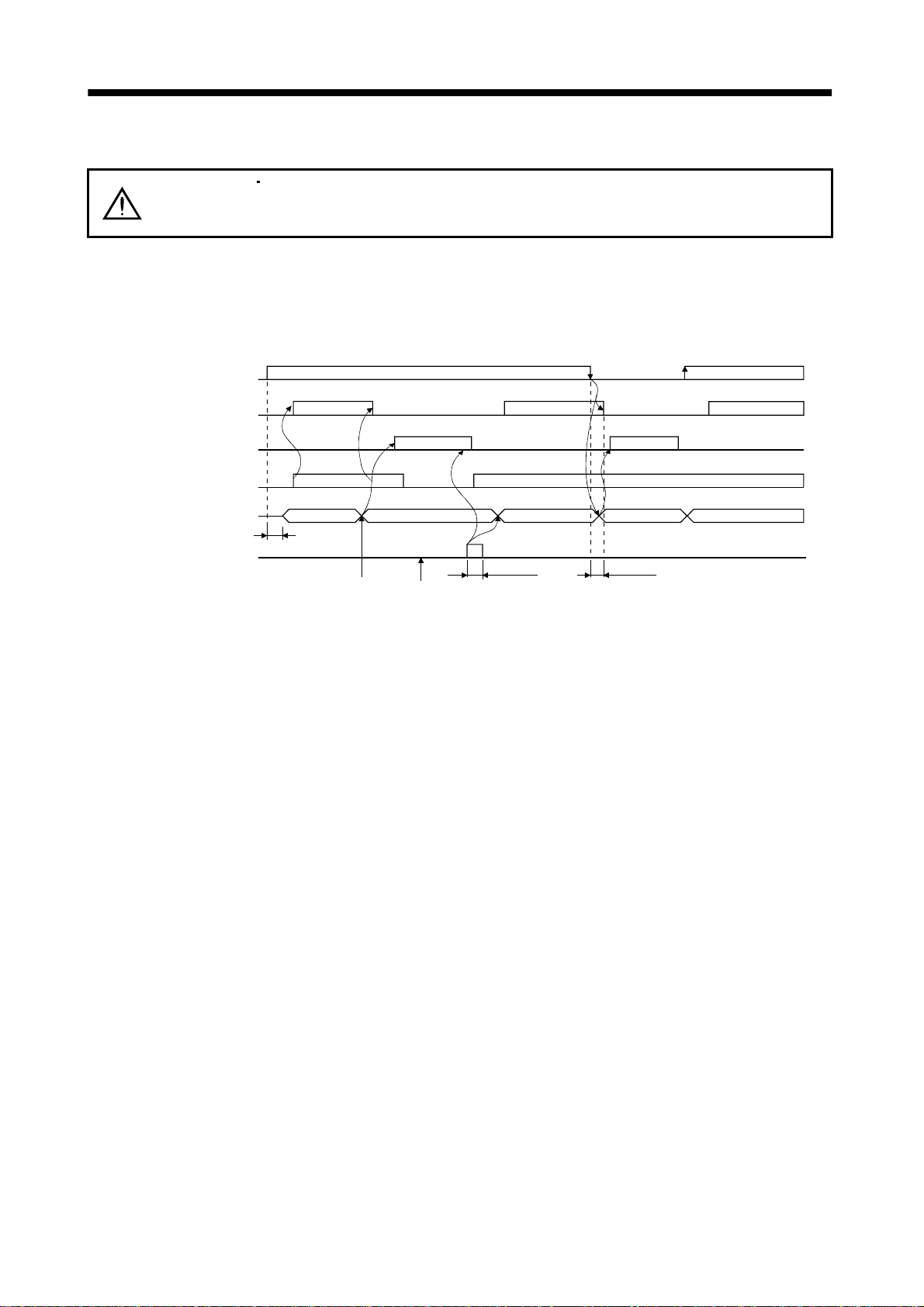
3. SIGNALS AND WIRING
3.3 Alarm occurrence timing chart
When an alarm has occurred, remove its cause, make sure that the operation
CAUTION
When an alarm occurs in the servo amplifier, the base circuit is shut off and the servo motor is coated to a
stop. Switch off the main circuit power supply in the external sequence. To deactivate the alarm, power
the control circuit off, then on or give the error reset or CPU reset command from the servo system
controller. However, the alarm cannot be deactivated unless its cause is removed.
Main circuit
Control circuit
Base circuit
Dynamic brake
Servo-on command
(from controll er )
Alarm
Reset command
(from controll er )
power
signal is not being input, ensure safety, and reset the alarm before restarting
operation.
ON
OFF
ON
OFF
Valid
Invalid
ON
OFF
ON
OFF
NO YES
1s
Alarm occurs.
Brake operation
NO
50ms or more
Remove cause of trouble.
Power off
Brake operation
YES
60ms or more
Power on
NO
(1) Overcurrent, overload 1 or overload 2
If operation is repeated by switching control circuit power off, then on to reset the overcurrent (32),
overload 1 (50) or overload 2 (51) alarm after its occurrence, without removing its cause, the servo
amplifier and servo motor may become faulty due to temperature rise. Securely remove the cause of
the alarm and also allow about 30 minutes for cooling before resuming operation.
(2) Regenerative alarm
If operation is repeated by switching control circuit power off, then on to reset the regenerative (30)
alarm after its occurrence, the external regenerative brake resistor will generate hea t, result ing in an
accident.
(3) Instantane ou s pow e r fa il ur e
Undervoltage (10) occurs if power is restored after a 60m s or longer power failure of the con trol circu it
power supply or after a drop of the bus voltage to or below 200VDC. If the power failure persists
further, the control circuit power switches off. When the power failure is rese t in this state, the alarm
is reset and the servo amplifier returns to the initial state.
3 - 6
Page 44

3. SIGNALS AND WIRING
e
3.4 Interfaces
3.4.1 Common line
The following diagram shows the power supply and its common line.
To conform to the EMC directive, refer to the EMC Installation Guide lines (IB(NA)67310).
Servo amplifier
24VDC
VDD
DI-1
COM
EM1
SG
<Isolated>
MBR
RA
Servo motor
SM
Ground
LA .etc
LAR
.etc
LG
SD
MO1
MO2
LG
TXD
RXD
MR
MRR
LG
SD
Analog monitor output
RS-232C
Servo motor encoder
CN2
Differential lin
driver output
35mA max.
3 - 7
Page 45

3. SIGNALS AND WIRING
3.4.2 Detailed description of the interfaces
This section gives the details of the I/O signal interfaces (refer to I/O Division in the table) indicated in
Sections 3.2.2.
Refer to this section and connect the interfaces with the external equipment.
(1) Digital input interface DI-1
Give a signal with a relay or open collector transistor.
Servo amplifier
24VDC
R: Approx. 4.7
For a transistor
Approx. 5mA
V
1.0V
CES
100 A
I
CEO
VDD
COM
EM1
Switch
SGTR
(2) Digital output interface DO-1
A lamp, relay or photocoupler can be driven. Provide a diode (D) for an inductive load, or an inrush
current suppressing resister (R) for a lamp load. (Permissible current: 40mA or less, inrush current:
100mA or less)
(a) Inductive load
Servo amplifier
24VDC
VDD
COM
MBR
SG
Load
If the diode is not
connected as shown,
the servo amplifier
will be damaged.
3 - 8
Page 46
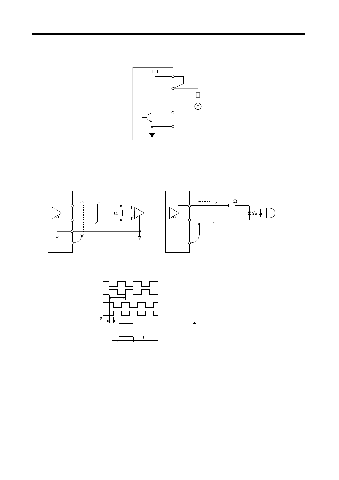
3. SIGNALS AND WIRING
(b) Lamp load
Servo amplifier
24VDC
(3) Encoder pul se outp ut D O- 2
(Differential line driver system)
1) Interface
Max. output current: 35mA
Servo amplifier Servo amplifier
LA
(LB, LZ)
Am26LS32 or equivalent High-speed photocoupler
VDD
COM
MBR
SG
LA
(LB, LZ)
R
100
LAR
(LBR, LZR)
LG
SD
2) Output pulse
150
Servo motor CCW rotation
LA
LAR
LB
LBR
LZ
LZR
OP
T
/2
LAR
(LBR, LZR)
SD
LZ signal varies 3/8T on its leading edge.
400 s or more
3 - 9
Page 47
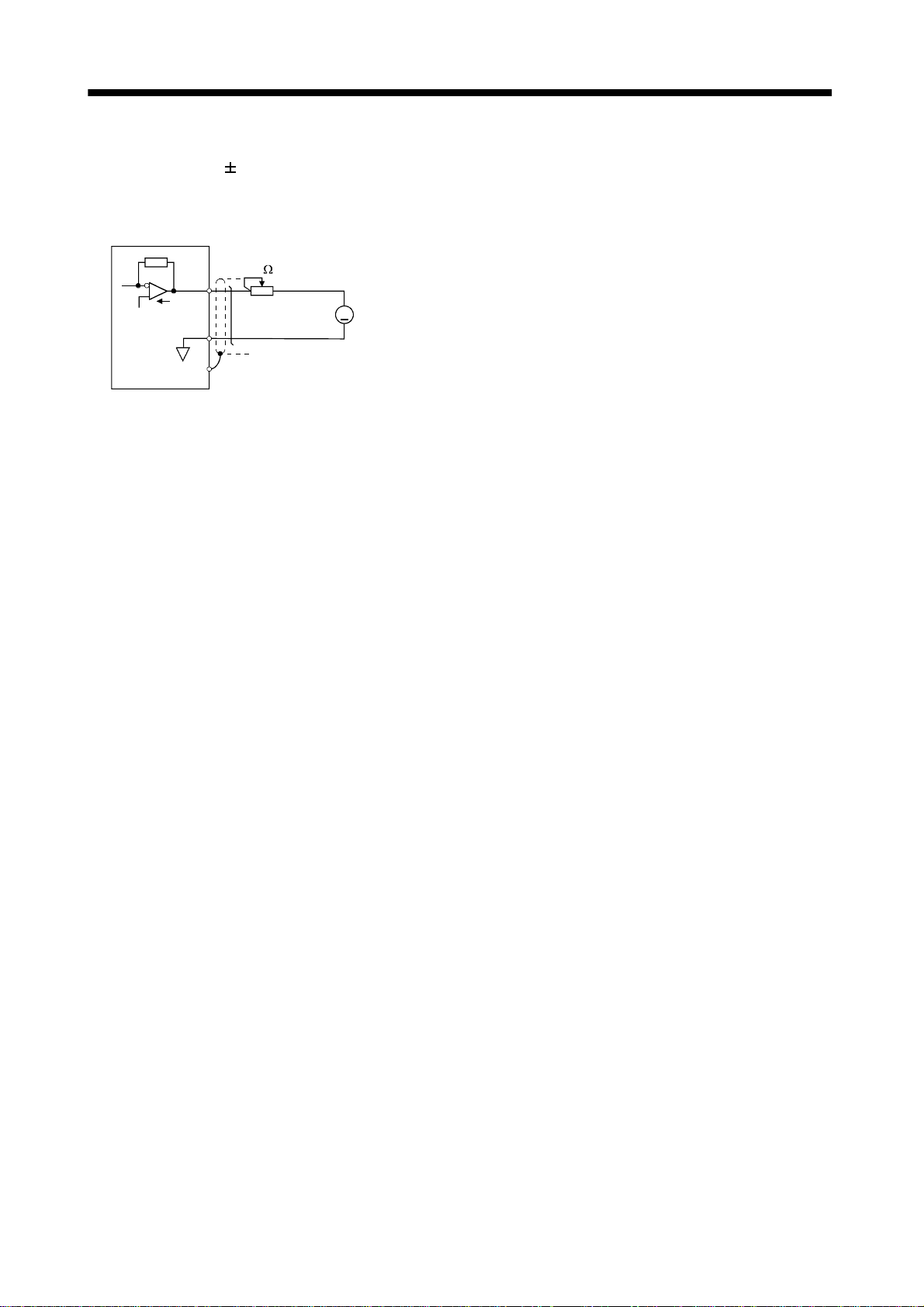
3. SIGNALS AND WIRING
(4) Analog output
Output voltage :
Max. output current :1mA
Resolution :10bit
Servo amplifier
10V
MO1
(MO2)
LG
SD
10k
Reading in one or
both directions
1mA meter
A
3 - 10
Page 48

3. SIGNALS AND WIRING
3.5 Power line circuit When the servo amplifier has become faulty, switch power off on the amplifier
power side. Continuous flow of a large current may cause a fire.
CAUTION
3.5.1 Connection example
Wire the power supply/main circuit as shown below so that power is shut off and the servo-on signal
turned off as soon as an alarm occurs, a servo forced stop is made valid, or a controller emergency stop is
made valid. A no-fuse breaker (NFB) must be used with the input cables of the power supply.
(1) For 3-phase 200 to 230VAC power supply
Use the trouble signal to switch power off. Otherwise, a regenerative brake
transistor fault or the like may o verheat the r egenerative b rake resist or, causing a
fire.
(Note)
Alarm
RA1
Controller
emergency stop
RA2
Forced
stop
OFF
ON
MC
MC
SK
NFB MC
Power supply
3-phase
200 to 230VAC
Forced stop
Servo amplifier
L
1
2
L
3
L
11
L
L
21
VDD
COM
EM1
SG
Note: Configure up the power supply circuit which switches off the magnetic contactor after detection of
alarm occurrence on the controller side.
3 - 11
Page 49

3. SIGNALS AND WIRING
(2) For 1-phase 100 to 120VAC or 1-phase 230VAC power supply
(Note 1)
Alarm
RA1
Controller
emergency stop
RA2
Forced
stop
OFF
ON
MC
MC
SK
Power supply
1-phase 100 to
120VAC or
1-phase 230VAC
NFB MC
Servo amplifier
L
1
2
L
(Note 2)
3
L
11
L
L
21
VDD
COM
Forced stop
EM1
SG
Note: 1. Configure up the power supply circuit which switches off the magnetic contactor after detection
of alarm occurrence on the controller side.
2. Not provided for 1-phase 100 to 120VAC.
3 - 12
Page 50

3. SIGNALS AND WIRING
3.5.2 Terminals
The positions and signal arrangements of the terminal blocks change with the capacity of the servo
amplifier. Refer to Section 10.1.
Symbol Signal Description
Supply L1, L2 and L3 with the following power:
For 1-phase 230VAC, connect the power supply to L
L1, L2, L3Main circuit power supply
Servo amplifier
Power supply
3-phase 200 to 230VAC,
50/60Hz
1-phase 230VAC,
50/60Hz
MR-J2S-10B to
70B
L
1L2L3
L
1L2
1-phase 100 to 120VAC,
50/60Hz
U, V, W Servo motor output Connect to the servo motor power supply terminals (U, V, W).
and leave L3 open.
1/L2
MR-J2S-100B
to 700B
MR-J2S-10B1
to 40B1
L
1L2
L11, L21Control circuit power supply
P, C, D Regenerative brake option
N
Return conv erter
Brake unit
Protective eart h (PE)
Servo amplifier
Power supply
1-phase 200 to 230VAC,
50/60Hz
1-phase 100 to 120VAC,
50/60Hz
MR-J2S-10B to 700B MR-J2S-10B1 to 40B1
L
11L21
L
11L21
1) MR-J2S-350B or less
Wiring is factory-connected across P-D (servo amplifier built-in regenerative
brake resistor).
When using the regenerative brake option, always remove the wiring from
across P-D and connect the regenerative brake option across P-C.
2) MR-J2S-500B or more
Wiring is factory-connected across P-C (servo amplifier built-in regenerative
brake resistor).
When using the regenerative brake option, always remove the wiring from
across P-C and connect the regene rative brake option a cr oss P-C .
Refer to Section 12.1.1 for details.
When using the return convert er o r b ra ke unit, connec t it across P-N.
Do not connect it to the servo amplifier of MR-J2S-350B or less.
Refer to Sections 12.1.2 and 12.1.3 for details.
Connect this terminal to the protective earth (PE) terminals of the servo motor
and contro l box for ground ing.
3 - 13
Page 51
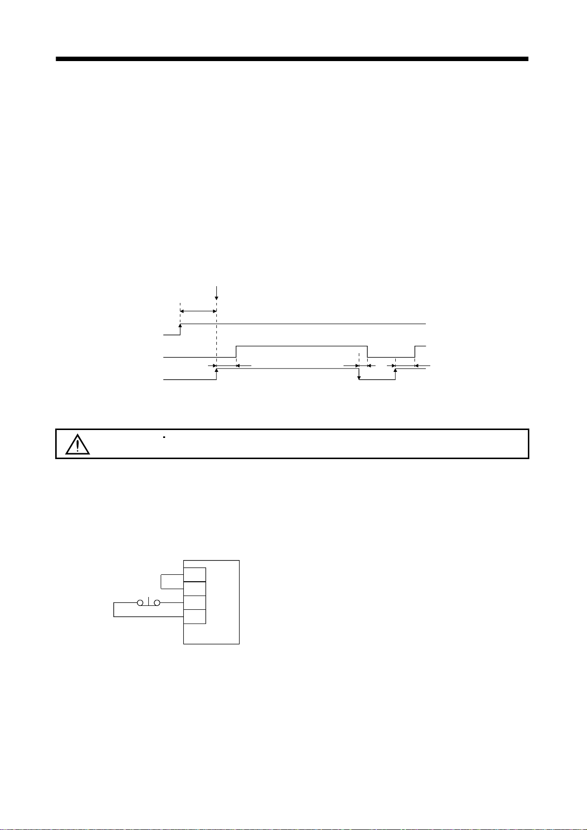
3. SIGNALS AND WIRING
3.5.3 Power-on sequence (1) Power-on procedure
1) Always wire the power supp ly as shown in above Section 3. 5.1 using the magnetic con tactor with
the main circuit power supply (3-phase 200V: L
external sequence to switch off the magnetic contactor as soon as an alarm occurs.
2) Switch on the control circuit power supply L
supply or before switching on the main circuit power supply. If the main circuit power supply is not
on, the display shows the corresponding warning. However, by switching on the main circuit power
supply, the warning disappears and the servo amplifier will operate properly.
3) The servo amplifier can accept the servo-on command within 3s the main circuit power supply is
switched on. (Refer to paragraph (2) in this section.)
(2) Timing chart
SON accepted
(3s)
Main circuit
Control circuit
Base circuit
Servo-on command
(from controller)
power
ON
OFF
ON
OFF
ON
OFF
1
, L2, L3, 1-phase 230V: L1, L2). Configure up an
11
, L21 simultaneously with the main circuit power
10ms 60ms60ms
(3) Forced stop
CAUTION
Install an emergency stop circuit externally to ensure that operation can be
stopped and power shut off immediately.
If the controller does not have an emergency stop function, make up a circuit which shuts off main
circuit power as soon as EM1-SG are opened at a forced stop. To ensure safety, always install a forced
stop switch across EM1-SG. By disconnecting EM1-SG, the dynamic brake is operated to bring the
servo motor to a stop. At this time, the display shows the servo forced stop warning (E6).
During ordinary operation, do not use forced stop signal to alternate stop and run. The service life of
the servo amplifier may be shortened.
Servo amplifier
VDD
COM
Forced stop
EM1
SG
3 - 14
Page 52

3. SIGNALS AND WIRING
3.6 Connection of servo amplifier and servo motor
3.6.1 Connection instructions
WARNING
Insulate the connections of the power supply terminals to prevent an electric
shock.
Connect the wires to the correct phase terminals (U, V, W) of the servo amplifier
CAUTION
and servo motor. Otherwise, the servo motor will operate improperly.
Do not connect AC power supply directly to the servo motor. Otherwise, a fault
may occur.
The connection method differs according to the series and capacity of the servo motor and whether or not
the servo motor has the electromagnetic brake. Perform wiring in accordance with this section.
(1) For grounding, connect the earth cable of the servo motor to the protective earth (PE) terminal of the
servo amplifier and connect the ground cable of the servo amplifier to the earth via the protective
earth of the control box. Do not connect them directly to the protective earth of the control panel.
Control box
Servo
amplifier
PE terminal
Servo motor
(2) Do not share the 24VDC interface power supply between the interface and electromagnetic brake.
Always use the power supply designed exclusively for the electromagnetic brake.
3.6.2 Connection diagram
The followin g table lists w iring me thods accord ing to the servo motor types. U se the conne ction diagram
which conforms to the servo motor used. For cables required for wiring, refer to Section 12.2.1. For
encoder cable connection, refer to Section 12.1.4. For the signal layouts of the connectors, refer to Section
3.6.3.
For the servo motor connector, refer to Chapter 3 of the Servo Motor Instruction Manual.
3 - 15
Page 53
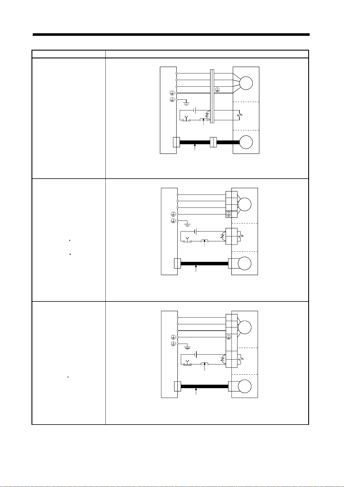
3. SIGNALS AND WIRING
g
g
Servo motor Connection diagram
Servo amplifier
U
V
W
(Note 1)
U (Red)
V (White)
W (Black)
(Green)
Servo motor
Motor
HC-KFS053 (B) to 73 (B)
HC-MFS053 (B) to 73 (B)
HC-UFS13 (B) to 73 (B)
HC-SFS121 (B) to 301 (B)
HC-SFS202 (B) to 702 (B)
HC-SFS203 (B)
353 (B)
HC-UFS202 (B) to 502 (B)
HC-RFS353 (B)
503 (B)
CN2
24VDC
EM1
To be shut off when servoon signal switches off or by
alarm signal
Encoder cable
B1
B2
(Note2)
Electroma
brake
Encoder
netic
Note:1. To prevent an electric shock, always connect the protective earth (PE) term i nal of the
servo amplifier to the protective earth (PE) of the control box.
2. This circuit applies to the servo motor with electromagnetic brake.
Servo amplifier
U
V
W
EM1
CN2
(Note 1)
24VDC
To be shut off when servoon signal switches off or by
alarm signal
Encoder cable
Servo motor
U
V
Motor
W
B1
Electro-
B2
magnetic
brake
Encoder
(Note2)
Note:1. To prevent an electric shock, always connect the protective earth (PE) term i nal of the
servo amplifier to the protective earth (PE) of the control box.
2. This circuit applies to the servo motor with electromagnetic brake.
Servo amplifier
Servo motor
HC-SFS81 (B)
HC-SFS52 (B) to 152 (B)
HC-SFS53 (B) to 153 (B)
HC-RFS103 (B) to 203 (B)
HC-UFS72 (B)
152 (B)
CN2
U
V
W
(Note 1)
24VDC
EM1
To be shut off when servoon signal switches off or by
alarm signal
Encoder cable
U
V
W
B1
B2
Motor
(Note2)
Electro-
netic
ma
brake
Encoder
Note:1. To prevent an electric shock, always connect the protective earth (PE) term i nal of the
servo amplifier to the protective earth (PE) of the control box.
2. This circuit applies to the servo motor with electromagnetic brake.
3 - 16
Page 54
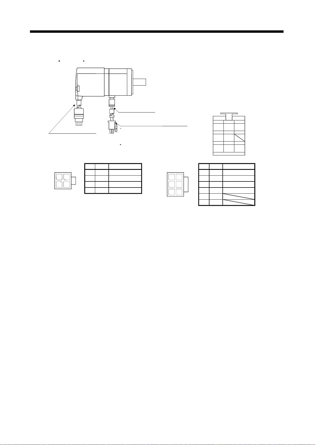
3. SIGNALS AND WIRING
3.6.3 I/O terminals (1) HC-KFS
Power supply
connector
5557-04R-210
HC-MFS HC-UFS3000r/min series
Power supply lead
4-AWG19 0.3m(0.98ft )
Power supply connector (molex)
Encoder cable 0.3m(0.98ft)
With connector 1-1721 69-9
(AMP)
Pin
Signal
1
13
24
2
3
4
Earth
U
V
W
Without electromagnetic brake
5557-04R-210 (receptacle)
5556PBTL (Female termina l)
With electromagnetic brake
5557-06R-210 (receptacle)
5556PBTL (Female termina l)
Lead wire color
Red
White
Black
Green/yellow
Power supply
connector
5557-06R-210
1
4
25
36
Encoder connector signal arrangement
123
MR
MRR BAT
456
MD
MDR
789
P5
LG SHD
Signal
Pin
1
2
3
4
5
6
Lead wire color
U
V
W
Green/yellowEarth
B1
B2
Red
White
Black
3 - 17
Page 55

3. SIGNALS AND WIRING
t
(2) HC-SFS HC-RFS HC-UFS2000 r/min series
Encoder connector
Motor plate
(Opposite side)
DOWN
UP
Brake connector
Power supply connector
Power supply connector signal arrangement
CE05-2A22-23PD-B
Key
Pin
A
F
E
A
G
H
C
D
B
C
B
D
(Earth)
E
F
(Note) B1
G
(Note) B2
H
Note:24VDC,without
polarity
Servo motor
HC-SFS81(B)
HC-SFS52(B) to 152(B)
HC-SFS53(B) to 153(B)
HC-SFS121(B) to 301(B)
HC-SFS202(B) to 502(B)
HC-SFS203(B)
HC-SFS702(B)
HC-RFS103(B) to 203 (B)
HC-RFS353(B) 503(B)
HC-UFS72(B) 152(B)
HC-UFS202(B) to 502(B)
CE05-2A24-10PD-B
Signal
U
V
W
E
Servo motor side connectors
For power supply For encoder
CE05-2A2223PD-B
CE05-2A24-
353(B)
Key
F
G
D
10PD-B
CE05-2A32-
17PD-B
CE05-2A2223PD-B
CE05-2A2410PD-B
CE05-2A2223PD-B
CE05-2A2410PD-B
A
B
C
Pin
A
B
C
D
E
F
MS3102A2029P
Signal
U
V
W
(Earth)
(Note) B1
(Note) B2
Electromagnetic
brake connector
The connector
for power is
shared.
MS3102A10SL4P
The connector
for power is
shared.
MS3102A10SL4P
G
Note:24VDC,withou
polarity
Encoder connector sig nal arr ang em en t
MS3102A20-29P
Key
Signal
Pin
A
M
L
K
J
H
B
A
C
N
TP
SR
G
F
D
E
MD
B
MDR
MR
C
MRR
D
E
BAT
F
LG
G
H
J
Pin
K
L
M
N
P
R
S
T
Signal
SD
LG
P5
Electromagnetic brake connector signal arrangement
MS3102A10SL-4P
Key
Pin
(Note)B1
A
(Note)B2
B
Note:24VDC without
A
B
polarity
3 - 18
Signal
Page 56

3. SIGNALS AND WIRING
3.7 Servo motor with electromagnetic brake Configure the electromagnetic brake operation circuit so that it is activated not only
by the servo amplifier signals but also by an external forced stop signal.
Contacts must be open when
servo-on signal is off or when an
alarm (trouble) is present and when
an electromagnetic brake signal.
Circuit must be
opened during
forced stop signal.
CAUTION
Servo motor
EM1RA
24VDC
Electromagnetic brake
The electromagnetic brake is provided for holding purpose and must not be used
for ordinary braking.
POINT
Refer to the Servo Motor Instruction Manual for specifications such as the
power supply capacity and operation delay time of the electromagnetic
brake.
Note the following when the servo motor equipped with electromagnetic brake is used for applications
requiring a brake to hold the motor shaft (vertical lift applications):
1) Do not share the 24VDC interface power supply between the interface and electromagnetic
brake. Always use the power supply designed exclusively for the electromagnetic brak e.
2) The brake will operate when the power (24VDC) switches off.
3) Switch off the servo-on command after the servo motor has stopped.
(1) Connection diagram
Servo amplifier
VDD
RA
Forced
stop
B1
Servo motor
COM
MBR
RA
24VDC
Z
B2
(2) Setting
In parameter No.21 (electromagnetic brake sequence output), set the time delay (Tb) from
electromagnetic brake operation to base circuit shut-off at a servo off time as in the timing chart in (3)
in this section.
3 - 19
Page 57

3. SIGNALS AND WIRING
(3) Timing charts
(a) Servo-on command (from controller) ON/OFF
Tb [ms] after the servo-on is switched off, the servo lock is released and the servo motor coasts. If
the electromagnetic brake is made valid in the servo lock status, the brake life may be shorter.
Therefore, when using the electromagnetic brake in a vertical lift application or the like, set Tb to
about the same as the electromagnetic brake operation delay time to prevent a drop.
Servo motor speed
0 r/min
Coasting
Tb
Electromagnetic brake
operation delay time
Base circuit
Electromagnetic
brake (MBR)
Servo-on command
(from controller)
ON
OFF
Invalid(ON)
Valid(OFF)
ON
OFF
(60ms)
(80ms)
(b) Emergency stop command (from controller) or forced stop signal (EM1) ON/OFF
Dynamic brake
Dynamic brake
Servo motor speed
Base circuit
Electromagnetic
brake interlock (MBR)
Emergency stop command
(from controller)
or
Forced stop (EM1)
(10ms)
ON
OFF
Invalid (ON)
Valid (OFF)
Invalid (ON)
Valid (OFF)
Electromagnetic brake
Electromagnetic brake
Electromagnetic brake release
(180ms)
(180ms)
Electromagnetic brake
operation delay time
3 - 20
Page 58

3. SIGNALS AND WIRING
A
(c) Alarm occurrence
Servo motor speed
Base circuit
Electromagnetic
brake interlock (MBR)
ON
OFF
Invalid(ON)
Valid(OFF)
Dynamic brake
Dynamic brake
Electromagnetic brake
Electromagnetic brake
(10ms)
Electromagnetic brake
operation delay time
Trouble (ALM)
No
Yes
(d) Both main and control circuit power supplies off
Dynamic brake
Dynamic brake
Electromagnetic brake
Electromagnetic brake
Electromagnetic brake
operation delay time
(Note 2)
Servo motor speed
Base circuit
Electromagnetic
brake interlock(MBR)
larm (ALM)
Main circuit
power
Control circuit
Note: Changes with the operating status.
ON
OFF
Invalid(ON)
Valid(OFF)
No
Yes
ON
OFF
(Note)
15 to 100ms
(10ms)
(10ms or less)
(e) Only main circuit power supply off (control circuit power supply remains on)
Dynamic brake
Dynamic brake
Electromagnetic brake
Electromagnetic brake
Servo motor speed
(10ms)
(Note 1)
15ms or more
Base circuit
Electromagnetic
brake interlock
(MBR)
Alarm
Main circuit power
supply
Note: 1. Changes with the operating status.
2. When the main circuit power supply is off in a motor stop status,
the main circuit off warning (E9) occurs and the ALM signal does not turn off.
ON
OFF
Invalid(ON)
Valid(OFF)
No
Yes
ON
OFF
10ms or less
Electromagnetic brake
operation delay time
(Note 2)
3 - 21
Page 59

3. SIGNALS AND WIRING
3.8 Grounding Ground the servo amplifier and servo motor securely.
WARNING
The servo amplifier switches the power transistor on-off to supply power to the servo motor. Depending on
the wiring and ground cablerouting, the servo amplifier may be affected by the switching noise (due to
di/dt and dv/dt) of the transistor. To prevent such a fault, refer to the following diagram and always
ground.
To conform to the EMC Directive, refer to the EMC Installation Guidelines (IB(NA)67310).
To prevent an electric shock, always connect the protective earth (PE) terminal of
the servo amplifier with the protective earth (PE) of the control box.
Control box
(Note 1)
Power supply
3-phase
200 to 230VAC,
1-phase
230VAC or
1-phase
100 to 120VAC
NFB
MC
Servo amplifier
1
L
2
L
Line filter
L
L
L
(Note 2)
3
11
21
CN1A
Servo system
controller
CN2
U
V
W
Ensure to connect it to PE
terminal of the servo amplifier.
Do not connect it directly
to the protective earth of
the control panel.
Servo motor
Encoder
U
V
SM
W
Outer
Protec tive ea rth(PE)
box
1
Note: 1. For 1-phase 230VAC, connect the power supply to L
There is no L
2. To reduce the influence of external noise, we recommend you to ground the bus cable near
the controller using a cable clamping fixture or to connect three or four data line filters in series.
for 1-phase 100 to 120VAC power supply.
3
L2 and leave L3 open.
3 - 22
Page 60
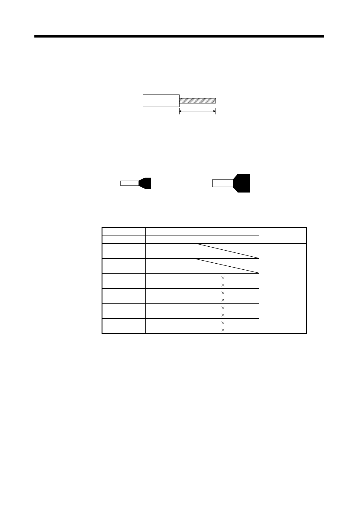
3. SIGNALS AND WIRING
3.9 Servo amplifier terminal block (TE2) wiring method
(1) Termination of the cables
Solid wire: After the sheath has been stripped, the cable can be used as it is. (Cable size: 0.2 to
2
2.5mm
Twisted wire: Use the cable afte r str ipp ing th e she ath and twi stin g the core . A t th is time , ta ke ca re to
)
Approx. 10mm
avoid a short caused by the loose wires of the core and the adjacent pole. Do not solder
the core as it m ay cause a con tact fault. (C able size : 0.2 to 2.5mm
2
)Alternatively, a bar
terminal may be used to put the wires together.(Phoenix contact)
Bar terminal for 1 cable
(Bar terminal ferrule with insulation sleeve)
Cable size Bar terminal type
[mm2] AWG For 1 cable For 2 cables
0.25 24
0.5 20
0.75 18
118
1.5 16
2.5 14
Al0.25-6YE
Al0.25-8YE
Al0.5-6WH
Al0.5-8WH
Al0.75-6GY
Al0.75-8GY
Al1-6RD
Al1-8RD
Al1.5-6BK
Al1.5-8BK
Al2.5-8BU
Al2.5-8BU-1000
(Twin ferrule with insulation sleeve)
Al-TWIN2
Al-TWIN2
Al-TWIN2
Al-TWIN2
Al-TWIN2
Al-TWIN2
Al-TWIN2
Al-TWIN2
Bar terminal for 2 cable
0.75-8GY
0.75-10GY
1-8RD
1-10RD
1.5-8BK
1.5-12BK
2.5-10BU
2.5-13BU
Crimping
tool
CRIMPFOX-UD6
3 - 23
Page 61
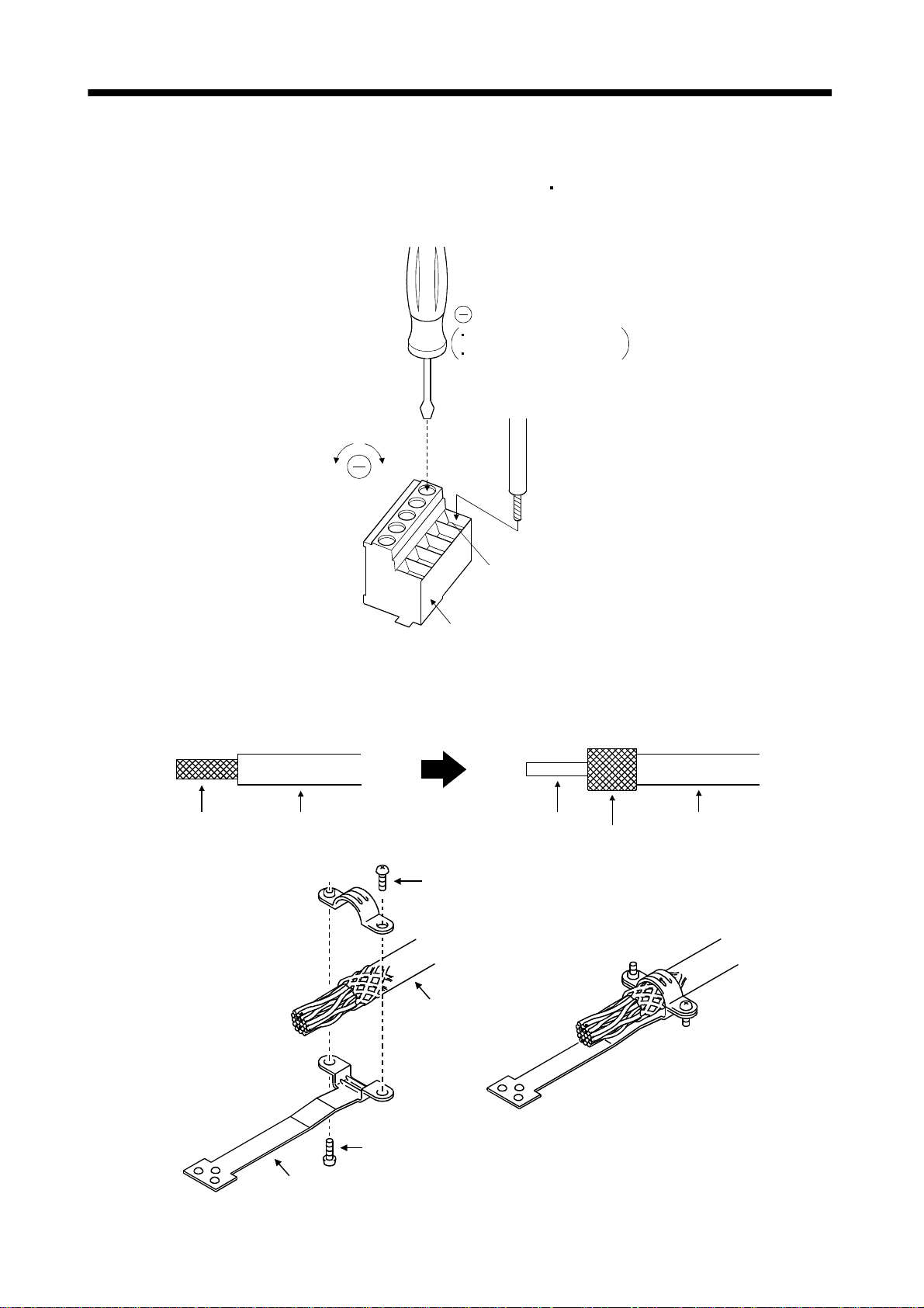
3. SIGNALS AND WIRING
(2) Connection
Insert the core of the cable into the opening and tighten the screw with a flat-blade screwdriver so that
the cable does not come off. (Tightening torque: 0.5 to 0.6N
opening, make sure that the screw of the terminal is fully loose.
When using a cable of 1.5mm
2
or less, two cables may be inserted into one opening.
Flat-blade screwdriver
Tip thickness 0.4 to 0.6mm
Overall width 2.5 to 3.5mm
m) Before insertin g the cable into the
To loosen.
To tighten.
Cable
Opening
Control circuit terminal block
3.10 Instructions for the 3M connector
When fabricating an encoder cable or the like, securely connect the shielded external conductor of the
cable to the ground plate as shown in this section and fix it to the connector shell.
External conductor Sheath
Strip the sheath.
External conductor
Pull back the external conductor to cover the sheath
Screw
SheathCore
Ground plate
Cable
Screw
3 - 24
Page 62
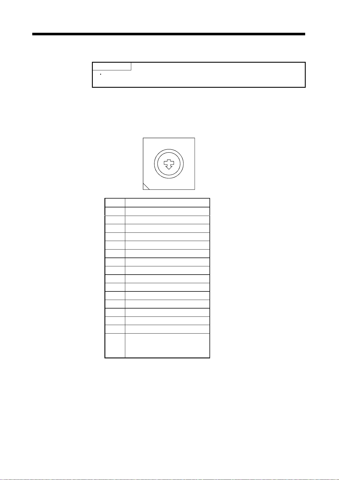
3. SIGNALS AND WIRING
3.11 Control axis selection POINT
The control axis number set to C S1 should be the same as the one set to
the servo system controller.
Use the axis select switch (CS1) to set the control axis number for the servo. If the same number s are set
to different control axes in a single communication system, the system will not operate properly. The
control axes may be set independently of the bus cable connection sequence.
Set the switch to "F" when executing the test operation mode using servo configuration softwa re.
Axis select switch (CS1)
8
9
7
6
5
4
3
2
A
B
C
D
E
F
1
0
No. Description
0Axis 1
1Axis 2
2Axis 3
3Axis 4
4Axis 5
5Axis 6
6Axis 7
7Axis 8
8 Not used
9 Not used
A Not used
B Not used
C Not used
D Not used
E Not used
F Test operation mode or
when machine analyzer is used
(Refer to Section 6.1.2)
3 - 25
Page 63

3. SIGNALS AND WIRING
MEMO
3 - 26
Page 64

4. OPERATION AND DISPLAY
4. OPERATION AND DISPLAY
4.1 When switching power on for the first time
Before starting operation, check the following:
(1) Wiring
(a) A correct power supply is connected to the power input ter minals (L
amplifier.
(b) The servo motor power supply terminals (U, V, W) of the servo amplifier match in phase with the
power input terminals (U, V, W) of the servo motor.
(c) The servo motor power supply terminals (U, V, W) of the servo amplifier are not shorted to the
power input terminals (L
(d) The servo amplifier and servo motor are grounded securely.
(e) Note the following when using the regenerative brake option, brake unit or power return converter:
1) For the MR-J2S-350B or less, the lead has been removed from across D-P of the control circui t
terminal block, and twisted cables are used for its wiring.
2) For the MR-J2S-500B or more, the lead has been removed from across P-C of the servo amplifier
built-in regenerative brake resistor, and twisted cables are used for its wiring.
(f) 24VDC or higher voltages are not applied to the pins of connector CN3.
(g) SD and SG of connector CN3 are not shorted.
(h) The wiring cables are free from excessive force.
(i) CN1A should be connected with the bus cable connected to the servo system controller or preceding
axis servo amplifier, and CN1B should connected with the bus cable connected to the subsequent
axis servo amplifier or with the termination connector (MR-A-TM.)
1
, L2, L3) of the servo motor.
1
, L2, L3, L11, L21) of the servo
(2) Axis number
The axis number setting of CS1 should be the same as that of the servo system controller. (Refer to
Section 3.11 . )
(3) Parameters
On the servo system controller screen or using the servo configuration software, make sure that
correct values have been set in the parameters.
(4) Environment
Signal cables and power cables are not shorted by wire offcuts, metallic dust or the like.
(5) Machine
(a) The screws in the servo motor installation part and shaft-to-machine connection are tight.
(b) The servo motor and the machine connected with the servo motor can be operated.
4 - 1
Page 65

4. OPERATION AND DISPLAY
4.2 Start up Do not operate the switches with wet hands. You may get an electric shock.
Do not operate the controller with the front cover removed. High-voltage terminals
WARNING
CAUTION
Connect the servo motor with a machine after confirming that the servo motor operates properly alone.
(1) Power on
When the main and control circuit power supplie s are switched on, "d1" (for the fir st axis) appears on
the servo amplifier display.
In the absolute position detection system, first power-on results in the absolute position lost (25) alarm
and the servo system cannot be switched on. This is not a failure and takes place due to the uncharged
capaci t or in the enc od e r.
The alarm can be deactivated by keeping power on for a few minutes in the alarm status and then
switching power off once and on again.
Also in the absolute position detection system, if power is switched on at the servo motor speed of
500r/min or higher, position mismatch may occur due to external force or the like. Power must
therefore be switched on when the servo motor is at a stop.
and charging area exposed and you may get an electric shock.
During power-on or operation, do not open the front cover. You may get an electric
shock.
Before starting operation, check the parameters. Some machines may perform
unexpected operation.
During power-on or soon after power-off, do not touch or close a parts (cable etc.)
to the servo amplifier heat sink, regenerative brake resistor, servo motor, etc. Their
temperatures may be high and you may get burnt or a parts may damaged.
(2) Parameter setting
Set the parameters according to the structure and specifications of the machine. Refer to Chapter 5 for
the parameter definitions.
Parameter No. Name Setting Description
7 Rotation direction setting 0
8 Auto tuning 1Used.
9 Servo response 5 Slow response (initial value) is selected.
After setting the above parameters, switch power off once. Then switch power on again to make the set
parameter values valid.
Increase in positioning address rotates the
motor in the CCW direction.
4 - 2
Page 66

4. OPERATION AND DISPLAY
(3) Servo-on
Switch the servo-on in the following procedure:
1) Switch on main circuit/control power supply.
2) The controller transmits the servo-on command.
When placed in the servo-on status, the servo amplifier is ready to operate and the servo motor is
locked.
(4) Home position return
Always perform home position return before starting positioning operation.
(5) Stop
If any of the following situations occurs, the servo amplifier suspends the running of the servo motor
and brings it to a stop.
When the servo motor is equipped with an electromagnetic brake, refer to Section 3.7.
Operation/command Stopping condition
Servo off command The base circuit is shut off and the servo motor coasts.
Servo system controller
Servo amplifier
Emergency stop command
Alarm occurrence
Forced stop signal
(EM1) OFF
The base circuit is shut off and the dynamic brake
operates to bring the servo motor to stop. The controller
emergency stop warni ng (E7) occurs.
The base circuit is shut off and the dynamic brake
operates to bring the servo moto r to stop.
The base circuit is shut off and the dynamic brake
operates to bring the servo motor to stop. The servo
forced stop warning (E6) occurs.
4 - 3
Page 67

4. OPERATION AND DISPLAY
4.3 Servo amplifier display
On the servo amplifier display (two-digit, seven-segment dis play), check the status of communication with
the servo system controller at power-on, check the axis number, and diagnose a fault at occurrence of an
alarm.
(1) Display sequence
Servo amplifier power ON
Waiting for servo system controller
power to switch ON
Servo system controller power ON
Initial data communication
with servo system controller
During emergency stop and forced stop
When alarm occurs,
alarm code appears.
Servo system controller power OFF
(Note)
Ready ON
(Note)
Servo ON
(Note)
Ordinary operation
Ready OFF/servo OFF
or
Emergency stop and forced stop
reset
Ready ON/servo OFF
Ready ON/servo ON
Servo system controller power ON
Note: The right-hand segments of b1, c1 and d1
indicate the axis number.
(Axis 1 in this example)
4 - 4
Page 68

4. OPERATION AND DISPLAY
(2) Indication list
Indication Status Description
AA Initializing
Ab Initializing
AC Initializing
Ad Initializing The initial parameters from the servo system controller were received.
AE Initialize completion Initial data communication with the servo system controller was completed.
(Note 1) b# Ready OFF The ready off signal from the servo system controller was received.
(Note 1) d# Servo ON The ready off signal from the servo system controller was received.
(Note 1) C# Servo OFF The ready off signal from the servo system controller was received.
(Note 2) ** Alarm Warning The alarm No./warning No. that occurred is displayed. (Refer to Section 9.1.)
88 CPU er ro r
(Note 3) b0.
(Note 1) b#.
d#.
c#.
(Note 3)
Test operati on mode
The servo amplifier was switched on when power to the servo system
controller is off.
Power to the servo system controller was switched off during power-on of
the servo amplifier.
The axis No. set to the servo system controller does not match the axis No.
set with the axis setting switch (CS1) of the servo amplifier.
A servo amplifie r fault occurred or an error took place in communication
with the servo system controller. In t his ca se, the indication changes:
"Ab"
"AC" "Ad" "Ab"
The servo system controller is faulty.
Communication started between the servo system controller and servo
amplifier.
JOG operation, positioning operation, programmed operation, DO forced
output.
Motor-less operation
Note: 1. # denotes any of numerals 0 to 8 and what it means is listed below:
# Description
0 Set to the test o peratio n mode.
1 Fir st axis
2 Second axis
3Third axis
4Fourth axis
5 Fifth axis
6 Sixth axis
7 Seventh axis
8 Eighth axis
2. ** indicates the warning/alarm No.
3. Requires the servo configuration software.
4 - 5
Page 69

4. OPERATION AND DISPLAY
4.4 Test operation mode The test operation mode is designed for servo operation confirmation and not for
CAUTION
By using a personal computer and the servo configuration software (MRZJW3-SETUP121E), you can
execute jog operation, positioning operation, motor-less operation and DO forced output without
connecting the motion controller.
(1) Test operation mode
(a) Jog operation
Jog operation can be performed without using the servo system controller. Use this operation with
the forced stop reset. This operation may be used independently of whether the servo is on or off
and whether the servo system controller is connected or not.
Exercise control on the jog operation screen of the Servo configuration software.
1) Operation pattern
machine operation confirmation. Do not use this mode with the machine. Always
use the servo motor alone.
If an operatio n fa ul t occur re d, u se th e fo rc ed stop (E M1 ) to make a st op .
Item Initial value Setting range
Speed [r/min] 200 0 to max. speed
Acceleration/deceleration time constant [ms] 1000 1 to 20000
2) Operation method
Operation Screen control
Forward rotation start Press Forward (G) button.
Reverse rotation start Press Reverse (R) button.
Stop Press Stop (O) button.
(b) Positioning operation
Positioning operation can be performed without using the servo system controller. Use this
operation with the forced stop reset. This operation may be used independently of whether the
servo is on or off and whether the servo system controller is connected or not.
Exercise control on the positioning operation screen of the servo configuration software.
1) Operation pattern
Item Initial value Setting range
Travel [pulse] 100000 0 to 9999999
Speed [r/min] 200 0 to max. speed
Acceleration/deceleration time constant [ms] 1000 1 to 50000
2) Operation method
Operation Screen control
Forward rotation start Press Forward (G) button.
Reverse rotation start Press Reverse (R) button.
Pause Press Pause (O) button.
4 - 6
Page 70

4. OPERATION AND DISPLAY
(c) Program operation
Positioning operation can be performed in two or more operation patterns combined, without using
the servo system controller. Use this operation with the forced stop reset. This operation may be
used independently of whether the servo is on or off and whether the servo system controller is
connected or not.
Exercise control on the programmed operation screen of the servo configuration software. For full
information, refer to the Servo Configuration Software Installation Guide.
Operation Screen Control
Start Press Start (G) button.
Stop Press Reset (O) button.
(d) Motorless operation
POINT
Motor-less operation may be used with the servo configuration software.
Usually, however, use motor-less operation which is available by making
the servo system controller parameter setting.
Without connecting the servo motor, output signals or status displays can be provided in response
to the servo system controller commands as if the servo motor is actually running. This operation
may be used to check the servo system controller sequence. Use this operation with the forced stop
reset. Use this operation with the servo amplifier connected to the servo system controller.
Exercise control on the motor-less operation screen of the servo configuration software.
1) Load conditions
Load Item Condition
Load torque 0
Load inertia moment ratio Same as servo motor inertia moment
2) Alarms
The following alarms and warning do not occur. However, the other alarms and warning s occur
as when the servo motor is connected:
Encoder error 1 (16)
Encoder error 2 (20)
Absolute position erasure (25)
Battery cable breakage warning (92)
(e) Output signal (DO) forced output
Output signals can be switched on/off forcibly independently of the servo status. Use this function
for output signal wiring check, etc.
Exercise control on the DO forced output screen of the servo configuration software.
4 - 7
Page 71

4. OPERATION AND DISPLAY
(2) Configuration
Configuration should be as in Section 3.1. Always install a forced stop switch to enable a stop at
occurrence of an alarm.
(3) Operation procedure
(a) Jog operation, positioning operation, program operation, DO forced output.
1) Switch power off.
2) Set CS1 to “F”.
When CS1 is set to the axis number and operation is performed by the servo system controller,
the test operation mode screen is displayed on the personal computer, but no function is
performed.
3) Switch servo amplifier power on.
When initialization is over, the display shows the following screen:
Decimal poin t fli ck e r s .
4) Perform operation with the personal computer.
(b) Motor-less operation
1) Switch off the servo amplifier.
2) Perform motor-less operation with the personal computer.
The display shows the following screen:
Decimal poin t flickers.
4 - 8
Page 72

5. PARAMETERS
5. PARAMETERS
CAUTION
Never adjust or change the parameter values extremely as it will make operation
instable.
POINT
When the servo amplifier is connected with the servo system controller, the
parameters are set to the values of the servo system controller. Switching
power off, then on makes the values set on the servo configuration software
invalid and the servo system controller values valid.
In the maker setting parameters, do not set any values other than the
initial values.
Setting may not be made to some parameters and ranges depending on the
model or version of the servo system controller. For details, refer to the
servo system controller user's manual.
5.1 Parameter write inhibit POINT
When setting the parameter values from the servo system controller, the
parameter No. 40 setting need not be changed.
In this servo amplif ier, the parame ters a re cla ssified in to the basic pa ramete rs (No. 1 to 11) , adju stment
parameters ( No. 12 to 26) and expan sion par ameter s (No. 2 7 to 40) accord ing to their safety aspec ts and
frequencies of use. The values of the basic parameters may be set/changed by the customer, but those of
the adjustment and expansion parameters cannot. When in-depth adjustment such as gain adjustment is
required, change the parameter No. 40 value to make all parameters accessible. Parameter No. 40 is
made valid by switching power off, then on after setting its value.
The following table indicates the parameters which are enabled for reference and write by parameter No.
40 setting.
Setting Operation Operation from controller Operation from servo configuration
0000(initial value)
000A
000C
000E
100E
Reference
Write
Reference
Write
Reference Parameter No.1 to 40
Write
Reference
Write
Reference Parameter No.1 to 40
Write
Parameter No.1 to 39 Parameter No.1 to 11 40
Parameter No.1 to 39 Parameter No.40
Parameter No.1 to 39
Parameter No.1 to 39 Parameter No.1 to 40
Parameter No.1 to 39
Parameter No.1 to 11
Parameter No.40
40
5.2 Lists POINT
For any parameter whose symbol is preceded by*, set the parameter value
and switch power off once, then switch it on again to make that parameter
setting valid.
5 - 1
Page 73

5. PARAMETERS
(1) Item list
Classifi-
cation
Note 1: Factory settings of the drive unit. Connecting it with the servo system controller and switching power on changes them to
No. Symbol Name
1 *AMS Amplifier setting (Note 2) 0000
2 *REG Regenerative brake resistor 0000
3 0080
4 000
5
6 *FBP Feedback pulse number 0
7 *POL Rotation direction sele ction 0
8 ATU Auto tuning 0001
Basic parameters
9 RSP Servo response 0005
10 TLP Forward rotation torque limit (Note 2) 300 %
11 TLN Reverse rotation torque limit (Note 2) 300 %
12 GD2 Ratio of load inertia to servo motor inertia (load inertia ratio) 7.0 times
13 P G1 Pos ition control gain 1 35 rad/s
14 VG1 Speed control gain 1 177 rad/s
15 P G2 Pos ition control gain 2 35 rad/s
16 VG2 Speed control gain 2 817 rad/s
17 VIC Speed integral compensation 48 ms
18 N CH Machine resonance suppression filter 1 (Notch filter) 0000
19 FFC Feed forward gain 0 %
20 INP In-po sition range 100 pulse
21 MBR Electromagnetic brake sequence output 0 ms
22 MOD Analog monitor output 0001
Adjustment parame te rs
23 *OP1 Optional function 1 0000
24 *OP2 Optional function 2 0000
25 LPF Low-pass filter/adaptive vibration suppression control 0000
26 For manufacturer setting 0
27 MO1 Analog monitor 1 offset 0 mV
28 MO2 Analog monitor 2 offset 0 mV
29 For manufacturer setting 0001
30 ZSP Zer o s p eed 50 r/min
31 ERZ Error excessive alarm level 80 0.1rev
32 OP5 Optional function 5 0000
33 *OP6 Optional function 6 0000
34 VPI PI-PID control switch-over position droop 0 pulse
35 For manufacturer setting 0
36 VDC Spe ed differential compensation 980
Expansion parameters
37 For manufacturer setting 0010
38 *ENR Encoder output pulses 4000 pulse/rev
39 For manufacturer setting 0
40 *BLK Parameter blocks (Note 2) 0000
the settings of th e s ervo system controller.
2: Setting and changing cannot be made from the peripheral software of the motion controller.
For manufacturer setting
(Note 1)
Initial
Value
1
Unit
Customer
setting
5 - 2
Page 74
5. PARAMETERS
(2) Details list
Classifi-
cation
No. Symbol Name and Function
1 *AMS Amplifier setting
Used to select the absolute position detection.
0 00
Absolute position detection selection
0: Invalid (Used in incremental system.)
1: Valid (Used in absolute position
detection system.)
Initial
Value
0000 Refer to
Unit
Setting
Range
name
and
function
column.
2*REG 0000 Refer to
Regenerative brake resistor
Used to select the regenerative brake option used.
0 0
Regenerative selection brake option
00: Not u sed
01: FR-RC FR-BU
05: MR-RB32
08: MR-RB30
09: MR-RB50
0B: MR-RB31
0C: MR-RB51
10: MR-RB032
11: MR-RB12
POINT
Wrong setting may cause the regenerative brake option to burn.
If the regenerative brake option selected is not for use with the
Basic parameters
3 0080
4 0000
5
6*FBP 0 Refer to
servo amplifier, parameter error (37) occu rs.
For manufacturer setting
Must not be changed.
1
Feedback pulse number
Set the number of pulses per revolution in the controller side
command unit. Information on the motor such as the feedback pulse
value, present position, droop pulses and within-one-revolution
position are derived from the values converted into the number of
pulses set here.
Setting Number of feedback pulses
0 16384
1 8192
6 32768
7 131072
255 Depending on the number of motor resolution p u l ses .
name
and
function
column.
name
and
function
column.
POINT
If the number of pulses set exceeds the actual motor
resolution, the motor resolution is set automatically.
5 - 3
Page 75

5. PARAMETERS
Classifi-
cation
Basic parameters
No. Symbol Name and Function
7 *POL Rotatio n direction select ion
Used to select the rotation direction of the servo motor.
0: Forward rotation (CCW) with the increase of the positioning
address.
1: Reverse rotation (CW) with the increase of the positioning
address.
CCW
CW
8 ATU Auto tuning
Used to select the gain adjustment mode of auto tuning.
0 00
Gain adjustment mode selection
(For details, refer to Section 6.1.1.)
Set
Gain adjustment
value
0
mode
Interpolation mode
Description
Fixes position control
gain 1
(parameter No. 13).
Initial
Value
0 Refer to
0001 Refer to
Unit
Setting
Range
name
and
function
column.
name
and
function
column.
Auto tuning mode 1
1
Auto tuning mode 2
3
4Simple manual
Manual mode 1
2
Manual mode 2
Ordinary auto tuning.
Fixes the load inertia
moment ratio set in
parameter No. 12.
Response level setting
can be changed.
adjustment.
Manual adjustment
of all gains.
5 - 4
Page 76
5. PARAMETERS
Classifi-
cation
Basic parameters
No. Symbol Name and Function
9 RSP Servo response
Used to select the response o f auto tuning.
0 00
Auto tuning response level selection
Set
Response
value
1
2
3
4
5
6
7
8
9
A
B
C
D
E
F 300Hz
If the machine hunts or generates large gear
sound, decrease the set value.
To improve performance, e.g. shorten the
settling time, increase the set value.
level
Low
response
Middle
response
High
response
Machine resonance
frequency guideline
15Hz
20Hz
25Hz
30Hz
35Hz
45Hz
55Hz
70Hz
85Hz
105Hz
130Hz
160Hz
200Hz
240Hz
Initial
Value
0005 Refer to
Unit
Setting
Range
name
and
function
column.
10 TLP Forward rotation torque limit
Assume that the rated torque is 100[%].
Used to limit the torque in the forward rotation driving mode and
reverse rotation regenerative mode.
In other than the test operation mode on the servo configuration
software, the torque limit value on the servo system controller side
is made valid.
11 TLN Reverse rotation torque limit
Assume that the rated torque is 100[%].
Used to limit the torque in the forward rotation driving mode and
forward rotation regenerative mode.
In other than the test operation mode on the servo configuration
software, the torque limit value on the servo system controller side
is made valid.
12 GD2 Ratio of load inertia to servo motor inertia (load inertia ratio)
Used to set the ratio of the load inertia (inertia moment) to the
inertia moment of the servo motor shaft. When auto tuning mode 1
and interpolation mode is selected, the result of auto tuning is
automatically used. (Refer to section 6.1.1)
13 PG1 Position loop gain 1
Used to set the gain of position loop 1. Increase the gain to improve
trackability performance in response to the position command.
Adjustment parame te rs
When auto turning mode 1,2 is selected, the result of auto turning is
automatically used.
300 % 0
to
500
300 % 0
to
500
7.0 times 0.0
to
300.0
35 rad/s 4
to
2000
5 - 5
Page 77
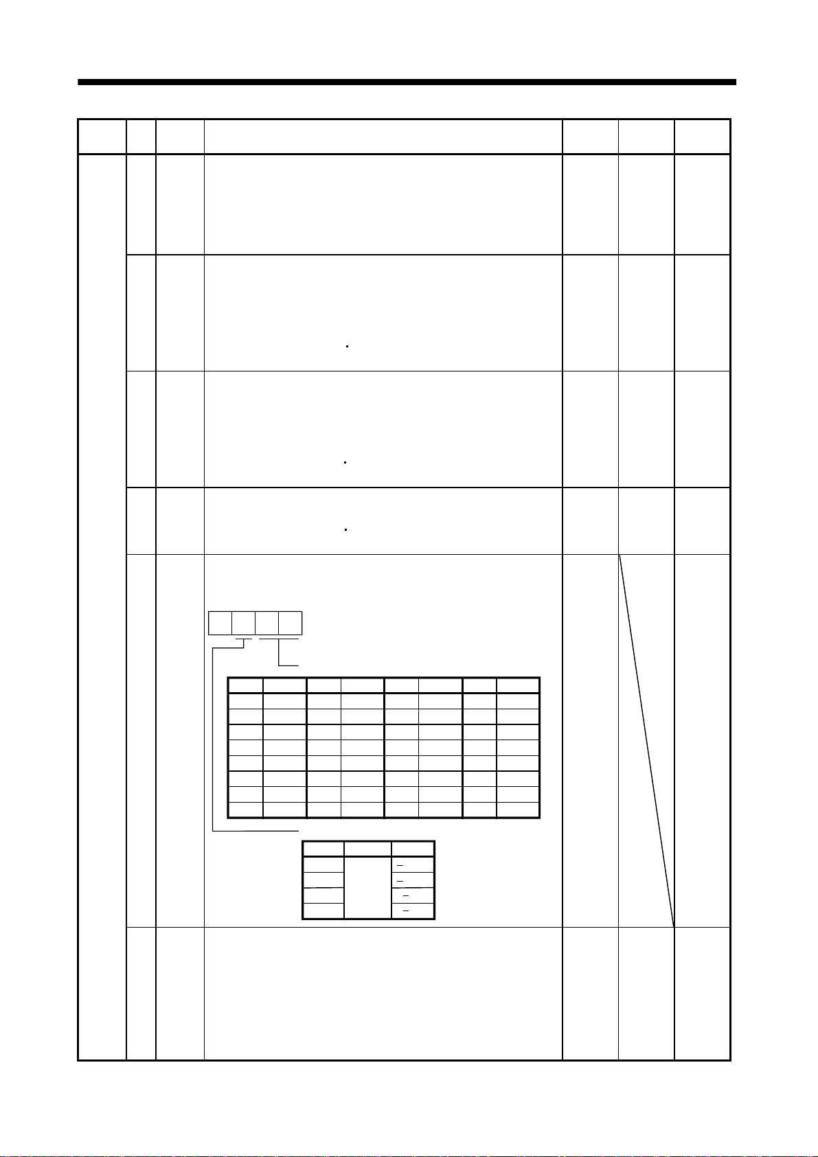
5. PARAMETERS
Classifi-
cation
No. Symbol Name and Function
14 VG1 Speed loop gain 1
Normally this parameter setting need not be changed. Higher setting
increases the response level but is liable to generate vibration and/o r
noise.
When auto tuning mode 1,2 and interpolation mode is selected, the
result of auto tuning is automatically used.
15 PG2 Position loop gain 2
Used to set the gain of the position loop.
Set this parameter to increase position response to load disturbance.
Higher setting increases the response level but is liable to generate
vibration and/or noise.
When auto tuning mode 1
2, manual mode and interpolation mode
is selected, the result of auto tuning is automatically used.
16 VG2 Speed loop gain 2
Set this parameter when vibration occurs on machines of low
rigidity or large backlash.
Higher setting increases the response level but is liable to generate
vibration and/or noise.
When auto tuning mode 1
2 and interpolation mode is selected, the
result of auto tuning is automatically used.
17 VIC Speed integral compensation
Used to set the constant of integral compensation.
When auto tuning mode 1
2 and interpolation mode is selected, the
result of auto tuning is automatically used.
18 NCH Machine resonance suppression filter 1 (Notch filter)
Used to select the machine resonance suppression filter.
(Refer to Section 7.2.)
0
Initial
Value
Unit
Setting
Range
177 rad/s 20
35 rad/s 1
817 rad/s 20
20000
48 ms 1
0 Refer to
name
and
function
column.
to
5000
to
1000
to
to
1000
Adjustment parame te rs
19 FFC Feed forward gain
Used to set the feed forward gain for position control. Set "100" to
nearly zero the droop pulse value when operation is performed at
constant speed.
Note that sudden acceleration/deceleration will increase overshoot.
As a guideline, when you set the feed forward gain for 100%, se t the
acceleration/deceleration time constant to/from the rated speed for 1s
or longer.
Setting
00
01
02
03
04
05
06
07
Notch frequency selection
Frequency
Invalid
4500
2250
1500
1125
900
750
642.9
Setting
08
09
0A
0B
0C
0D
0E
0F
Frequency
Notch depth selection
Setting Depth Gain
0
1
2
3
562.5
500
450
409.1
375
346.2
321.4
300
Deep
to
Shallow
Setting
10
11
12
13
14
15
16
17
40dB
14dB
Frequency
281.3
264.7
250
236.8
225
214.3
204.5
195.7
8dB
4dB
Setting
18
19
1A
1B
1C
1D
1E
1F
Frequency
187.5
180
173.1
166.7
160.1
155.2
150
145.2
0%0
to
100
5 - 6
Page 78
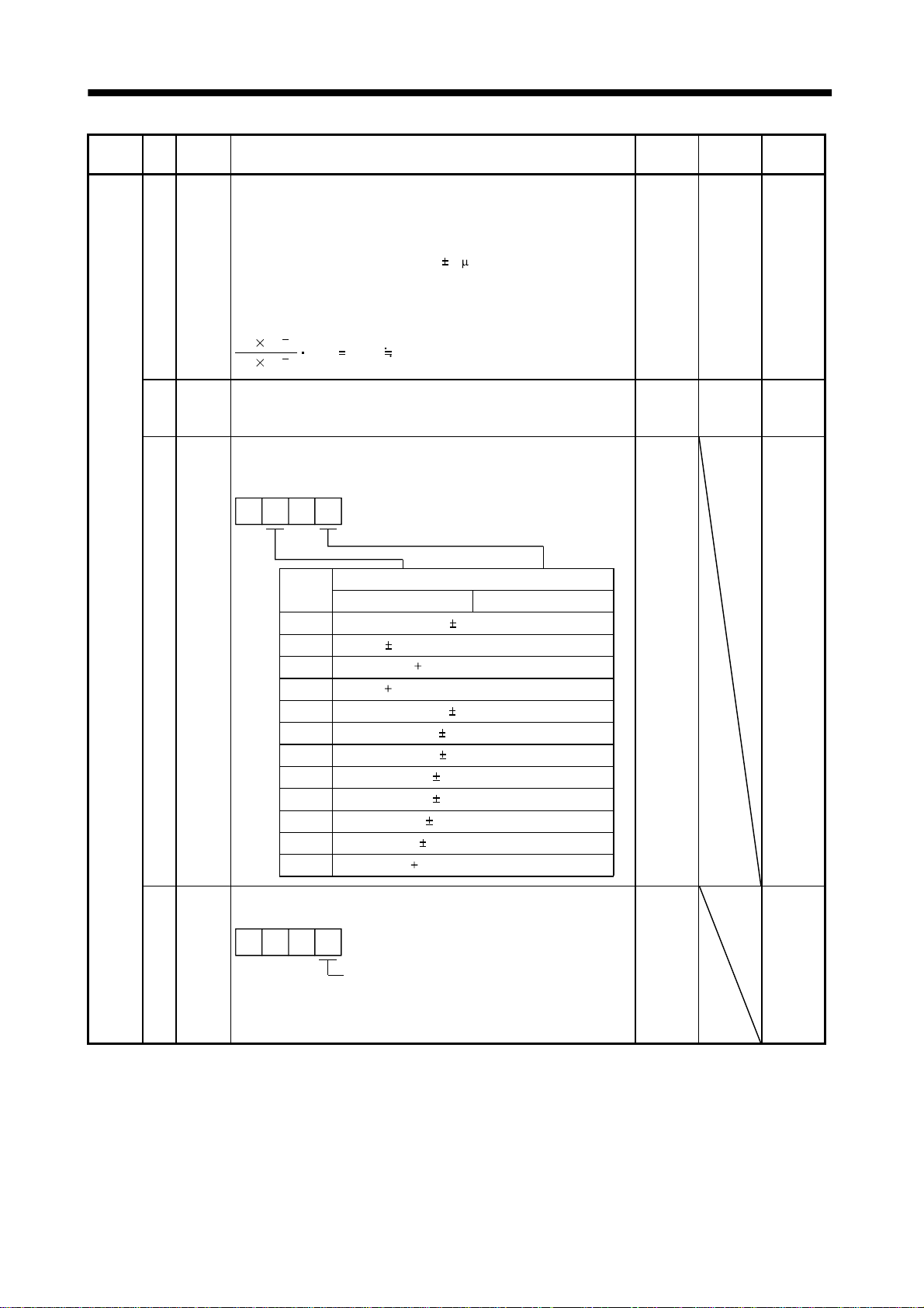
5. PARAMETERS
Classifi-
cation
Adjustment parame te rs
No. Symbol Name and Function
20 INP In-position range
Used to set the droop pulse range in which the in-position signal
(INP) will be output to the controller. Make setting in the feedback
pulse unit (parameter No. 6).
For example, when you want to set
ballscrew is direct coupled, the lead is 10mm, and the feedback
pulses are 8192 pulses/rev (parameter No. 6 : 1), set "8" as indicated
by the following expression:
10 10
10 10
21 MBR Electromagnetic brake sequence output
Used to set a time delay (Tb) from when the electromagnetic brake
interlock signal (MBR) turns off until the base circuit is shut off.
22 MOD Analog monitor output
Used to select the signal provided to the analog monitor.
(Refer to Section 5.3.)
6
8192 8.192 8
3
10 m in the conditions that the
00
Setting
0
Servo motor speed ( 8V/max. speed)
1 Torque ( 8V/max. torque)
2 Motor speed ( 8V/max. speed)
3 Torque ( 8V/max. torque)
4 Current command ( 8V/max. current command)
5 Command speed ( 8/max. speed)
6 Droop pulses ( 10V/128 pulses)
7 Droop pulses ( 10V/2048 pulses)
8 Droop pulses ( 10V/8192 pulses)
9 Droop pulses ( 10V/32768 pulses)
A Droop pulses ( 10V/131072 pulses)
B Bus voltage ( 8V/400V)
Analog monitor output selection
ch1
ch2
Initial
Value
100 pulse 0
100 ms 0
0001 Refer to
Unit
Setting
Range
to
50000
to
1000
name
and
function
column.
23 *OP1 Optional function 1
Used to make the servo forced stop function invalid.
000
Servo forced stop selection
0: Valid (Use the forced stop signal (EM1).)
1: Invalid (Do not use the forced stop signal (EM1).)
Automatically switched on internally
5 - 7
0000 Refer to
name
and
function
column.
Page 79
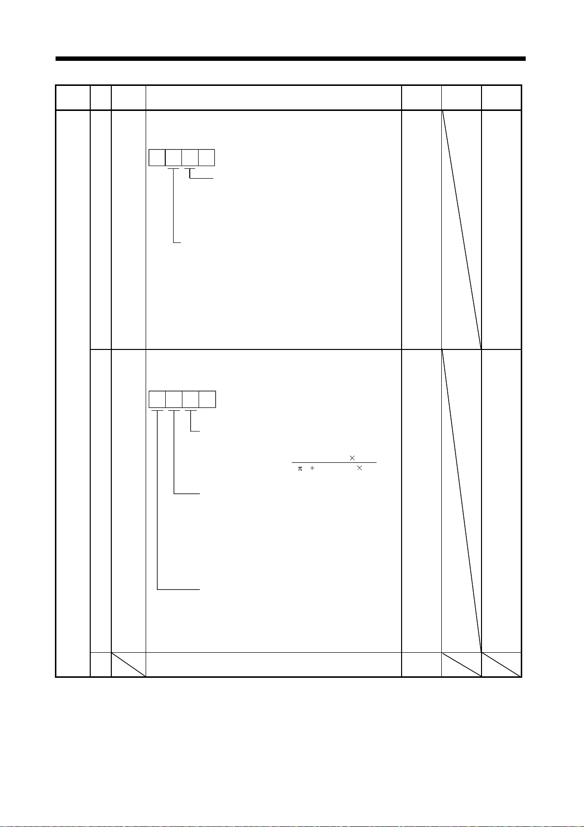
5. PARAMETERS
g
y
Classifi-
cation
No. Symbol Name and Function
24 *OP2 Optional function 2
Used to select slight vibration suppression control and motor-less
operation
0 0
Slight vibration suppression control selection
Made valid when auto tuning selection is
set to "0002" in parameter No.8.
Used to suppress vibration at a stop.
0: Invalid
1: Valid
Motor-less operation selection
0: Invalid
1: Makes motor-less operation valid.
When motor-less operation is made valid, signal output or
status display can be provided as if the servo motor is running
actually in response to the servo system controller command,
without the servo motor being connected.
Motor-less operation is performed as in the motor-less
operation using the servo configuration software.
(Refer to (d), (1) in Section 4.4.)
25 LPF Low-pass filter/adaptive vibration suppression control
Used to select the low-pass filter and adaptive vibration suppression
control. (Refer to Chapter 7.)
0
Initial
Value
0000 Refer to
0000 Refer to
Unit
Setting
Range
name
and
function
column.
name
and
function
column.
Adjustment parame te rs
26 For manufacturer setting
Must not be changed.
Low-pass filter selection
0: Valid (Automatic adjustment)
1: Invalid
When you choose "valid",
bandwidth filter is set automatically.
Adaptive vibration suppression control selection
0: Invalid
1: Valid
Machine resonance frequency is always detected
and the filter is generated in response to resonance to
suppress machine vibration.
2: Held
The characteristics of the filter generated so far are
held, and detection of machine resonance is stopped.
Adaptive vibration suppression control sensitivity
selection
Used to select the sensitivity of machine resonance
detection.
0: Normal
e sensitivit
1: Lar
VG2 setting 10
2 (1 GD2 setting 0.1)
[Hz]
0
5 - 8
Page 80

5. PARAMETERS
Classifi-
cation
No. Symbol Name and Function
27 MO1 Analog monitor 1 offset
Used to set the offset voltage of the analog monitor ch1 output.
28 MO2 Analog monitor 2 offset
Used to set the offset voltage of the analog monitor ch2 output.
29 For manufacturer setting
Must not be changed.
30 ZSP Zero speed
Used to set the output range of the zero speed signal (ZSP).
31 ERZ Error excessive alarm level
Used to set the output range of the error excessive alarm.
32 OP5 Optional function 5
Used to select PI-PID control switch-over.
0 00
PI-PID control switch over selection
0: PI control is always valid.
1: Droop-based switching is valid in position
control mode (refer to parameter No. 34).
2: PID control is always valid.
Initial
Value
0mV999
0mV999
0001
50 r/min 0
80 0.1rev 0
0000 Refer to
Unit
Setting
Range
to
999
to
999
to
10000
to
1000
name
and
function
column.
33 *OP6 Option function 6
Used to select the serial communication baudrate, serial
communication response delay time setting and encoder output
pulse setting.
0
Expansion parameters
34 VPI PI-PID control switch-over position droop
Used to set the position droop value (number of pu lses) at which PI
control is switched over to PID control.
Set "0001" in parameter No. 32 to make this function valid.
35 For manufacturer setting
Must not be changed.
36 VDC Speed differential compensation
Used to set the differential compensation.
37 For manufacturer setting
Must not be changed.
Serial communication baudrate selection
0: 9600[bps]
1: 19200[bps]
2: 38400[bps]
3: 57600[bps]
Serial communication response delay time
0: Invalid
1: Valid , replay sent in 800 s or more
Encoder output pulse setting selection
(refer to parameter No.38)
0: Output pulse setting
1: Division ratio setting
0000 Refer to
name
and
function
column.
0pulse0
to
50000
0
980 0
to
1000
0010
5 - 9
Page 81

5. PARAMETERS
Classifi-
cation
Expansion parameters
No. Symbol Name and Function
38 *ENR Encoder outpu t pulses
Used to set the encoder pulses (A-phase, B-phase) output by the
servo amplifier.
Set the value 4 times greater than the A-p hase and B-phas e pulses.
You can use parameter No.33 to choose the output pulse setting or
output division ratio setting.
The number of A-phase and B-phase pulses actually output is 1/4
times greater than the preset number of pulses.
The maximum output frequency is 1.3Mpps (after multiplication by
4). Use this parameter within this range.
For output pulse designation
Set "0
" (initial value) in parameter No. 33.
Set the number of pulses per servo motor revolution.
Output pulse
At the setting of 5600, for example, the actually output A-phase
and B-phase pulses are as indicated be lo w:
A-phase and B-phase output pulses
For output division ratio setting
Set "1
The number of pulses per servo motor re volution is divided by the
set value.
Output pulse
At the setting of 8, for example, the actually output A-phase and
B-phase pulses are as indicate d belo w:
A-phase and B-phase output pulses 4096[pulse]
39 For manufacturer setting
Must not be changed.
40 *BLK 0000 Refer to
Parameter blocks
Setting Operation Operat i on from
(initial
value)
000C
100E
set value [pulses/rev]
5600
1400[pulse]
4
" in parameter No. 33.
Resolution per servo motor revol ution
Set value
13107241
8
Operation from
controller
Reference0000
Write
Reference000A
Write
Reference Parameter No.1
Write
Reference000E
Write
Reference Parameter No.1
Write
Parameter No.1
to 39
Parameter No.1
to 39
Parameter No.1
to 39
Parameter No.1
to 39
Parameter No.1
to 39
servo configuration
Parameter No.1
to 11
40
Parameter No.40
to 40
Parameter No.1
to 11
40
Parameter No.1
to 40
to 40
Parameter No.40
[pulses/rev]
Initial
Value
4000 pulse/rev 1
0
Unit
Setting
Range
to
65535
name
and
function
column.
5 - 10
Page 82
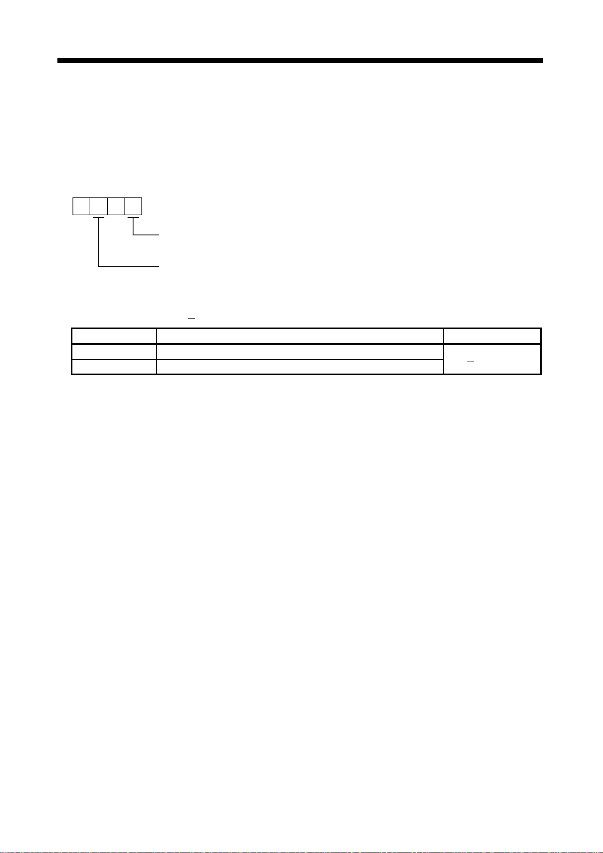
5. PARAMETERS
5.3 Analog output
The servo status can be output to two channels in terms of voltage. Use this function when using an
ammeter to monitor the servo status or synchronizing the torque/speed with the other servo.
(1) Setting
Change the following digits of parameter No.22:
Parameter No. 22
00
Analog monitor ch2 output selection
(Signal output to across MO2-LG)
Analog monitor ch1 output selection
(Signal output to across MO1-LG)
Parameters No.27 and 28 can be used to set the offset voltages to the analog output voltages. The
setting range is between
Parameter No. Description Setting range [mV]
27 Used to set the offset voltage for the analog monitor ch1 output.
28 Used to set the offset voltage for the analog monitor ch2 output.
999 and 999mV.
999 to 999
5 - 11
Page 83

5. PARAMETERS
(2) Setting description
The servo amplif ier is factory-se t to output the mo tor speed to ch 1 and the gen erated torque to ch2.
The setting can be changed as listed below by changing the parameter No.22 value:
Refer to (3) in this section for the measurement point.
Setting Output item Description Setting Output item Description
0 Mo t or speed
8[V]
CCW direction
6 Droop pulses
(
10V/128pulse)
10[V]
CCW direction
1Torque
2 Mo t or speed
3Torque
Max. speed
CW direction
8[V]
Max. torque
Driving in CW direction
CW
direction
Max. speed
CW direction
Driving in
8[V]
8[V]
0
Max. speed
8[V]
Driving in CCW direction
0
Max. torque
8[V]
CCW
direction
0
Max. speed
Driving in
CCW direction
7 Droop pulses
(
10V/2048pulse)
8 Droop pulses
(
10V/8192pulse)
9 Droop pulses
(
10V/32768pulse)
128[pulse]
CW direction
10[V]
2048[pulse]
CW direction
10[V]
8192[pulse]
CW direction
10[V]
32768[pulse]
0
128[pulse]
10[V]
CCW direction
0
2048[pulse]
10[V]
CCW direction
0
8192[pulse]
10[V]
CCW direction
0
32768[pulse]
4 Current command
(Torque command)
5Command pulse
frequency
Max. torque
8[V]
Max. current
command
(Max. torque
command)
CW direction
8[V]
Max. speed
CW direction
Max. torque
0
CCW direction
0
Max. current
command
(Max. torque
command)
8[V]
CCW direction
0
Max. speed
8[V]
5 - 12
A Droop pulses
(
10V/131072pulse)
BBus voltage
CW direction
10[V]
131072[pulse]
CW direction
8[V]
0
10[V]
CCW direction
0
131072[pulse]
10[V]
400[V]
Page 84
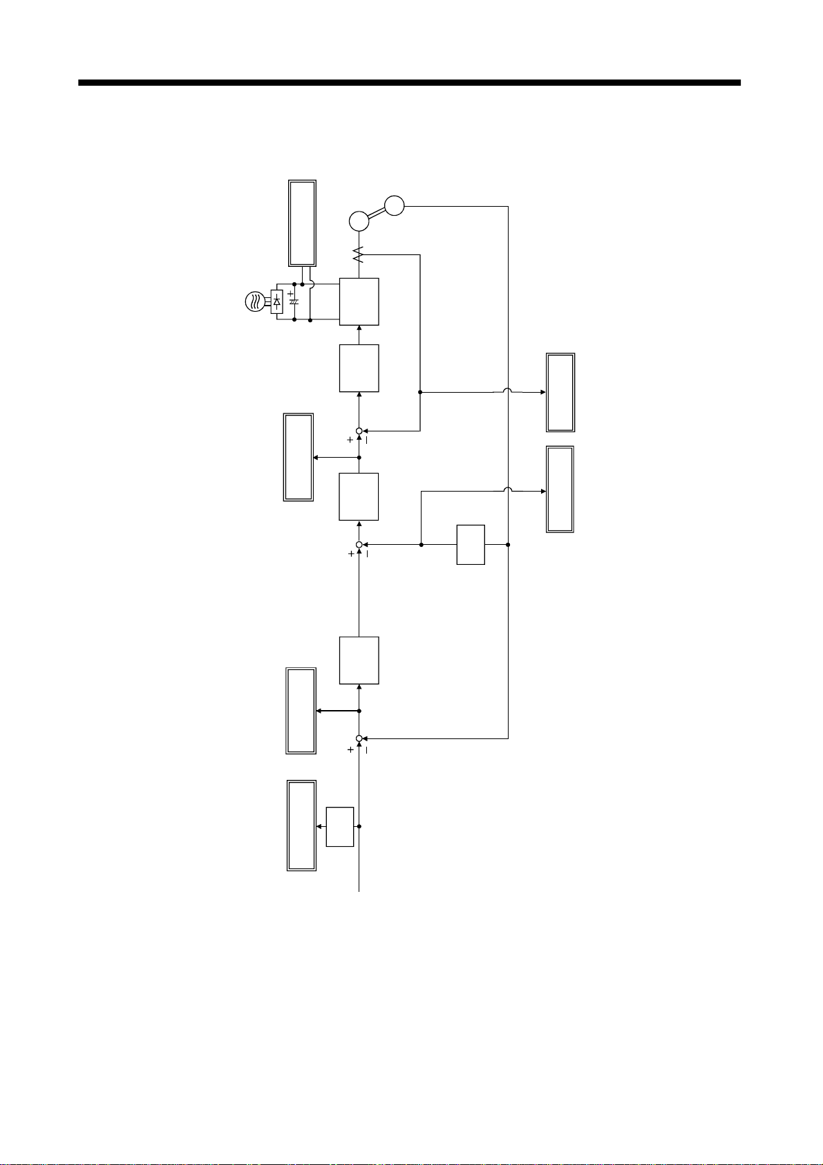
5. PARAMETERS
(3) Analog monitor block diagram
control
control
Encoder
Current feedback
Position feedback
Torque
Motor speed
ential
Differ-
Servo Motor
Bus voltage
Current
encoder
PWM M
Current
Current
command
Speed
Droop pulse
Command
pulse frequency
Speed
ential
Differ-
command
Position
Command
control
pulse
5 - 13
Page 85

5. PARAMETERS
5.4 Replacement of MR-J2- B by MR-J2S- B
When using the MR-J2SMR-J2S-
B, you cannot use some parameter functions. Read this section carefully and set appropriate
B on the servo system controller peripheral software incompatible with the
values in the parameters.
5.4.1 Main modifications made to the parameters
The following table lists the parameters whose settings have been modified from the MR-J2to the MR-J 2S-
B. The peripheral software of the servo system controller may not be compatible with
B or added
some parame ters whose se ttings are diff erent or have been added . For det ails, refer to the serv o syste m
controller manual.
Parameter
No.
6 FBP Feedback pulse number The encoder resolution of the
8 ATU Auto tuning Gain adjustment modes were
9 RSP Servo response The response level setting range
18 NCH Machine resonance
20 INP In-position range The setting unit became the
22 MOD Analog monitor output The data that may be output by
25 LPF Low-pass filter/adaptive
31 ERZ Error excessive alarm level The setting unit was changed in
33 OP6 Optional function 6 The communication baudrate
38 ENR Encoder output pulses The encoder feedback pulses can
Code Name Main modifications/additions
compatible motor changed to
131072 pulses/rev.
increased.
was increased to meet the
enhanced response.
The machine resonan ce
suppression filter 1
(Notch filter)
vibration suppression control
suppression filter (notch filter)
setting range was increased.
feedback pulse unit in
parameter No. 6.
analog monitor was added.
The low-pass filter and adaptive
vibration suppression control
functions were newly added.
response to the enhanced
resolution (131072 pulses/rev) of
the encoder.
with the personal computer was
changed to max. 57600bps.
be output from the servo
amplifier. These pulses can be
set.
(Note) Setting from peripheral
software of conventional servo
system controller
Setting cannot be made.
The resolution is 16384
pulses/rev.
Setting can be made but the
added modes cannot be
used.
Some response levels cannot
be set.
Some filter frequencies
cannot be set.
Setting can be made.
Setting can be made but the
bus voltage cannot be set.
Setting can be made.
Setting can be made but the
setting unit is [0.1 rev].
Setting cannot be made.
Setting cannot be made.
Note. As of January, 2000
5 - 14
Page 86

5. PARAMETERS
5.4.2 Explanation of the modified parameters (1) Feedback pulse number (parameter No. 6)
This parameter was newly added to the MR-J2 Scontroller is not co mpatible with the MR- J2S-
B. If the peripheral software of the servo system
B, this parameter setting cannot be changed. When
the servo motor used is the HC-KFS or HC-MFS, the feedback pulse number is 8192 pulses/rev, and
when it is the HC-SFS, HC-RFS or HC-UFS, the feedback pulse number is 16384 puls es/rev.
(2) Auto tuning (parameter No. 8)
The set value s of this parameter were newly added to the MR-J2 Sthe servo system controller is not compatible with the MR-J2S-
B. If the peripheral software of
B, the parameter settings are as
indicated below. The auto tuning mode 2 and manual mode 1 cannot be used.
0 00
Gain adjustment mode selection
(For details, refer to Section 6.1.1.)
Set value Gain adjustment mode
Interpol ation mode
0
Auto tuning mode 1
1
Manual mode 2
2 Manual adjustment of all gains.
Fixes position control gain 1
(parameter No. 13).
Ordinary auto tuning.
Description
(3) Servo response (parameter No. 9)
The set values of this parameter were newly added to the MR-J2S-
B. In addition, the machine
resonance frequency guidelines corresponding to the set values were changed. If the peripheral
software of the servo system controller is not compatible with the MR-J2S-
B, the parameter settin g s
are as indicated below.
0 00
Auto tuning response level selection
Set
value
Response
level
1
2
3
4
5
6
7
8
9
A
B
C 160Hz
Low
response
Middle
response
High
response
Machine resonance
frequency guideline
15Hz
20Hz
25Hz
30Hz
35Hz
45Hz
55Hz
70Hz
85Hz
105Hz
130Hz
5 - 15
Page 87

5. PARAMETERS
(4) Machine resonance suppression filter 1 (parameter No. 18)
The settings of this parameter were changed for the MR- J2Sservo system controller is not compatible with the MR-J2Sindicated below. The notch depth is
0
40dB.
00
Notch frequency selection
Set value Frequency
Invalid
0
1
2
3
4
5
6
7
Notch depth selection
Set value Depth Gain
0 Deep 40dB
4500
2250
1500
1125
B. If the peripheral software of the
B, the parameter settings are as
900
750
642.9
(5) In-position range (parameter No. 20)
The setting o f this parame ter was change d for the MR-J2 S-
B. The setting unit was changed from
the conventional input pulse unit to the feedback pulse unit. For deta ils, refer to Section 5.2.
(6) Analog moni to r ou tp ut ( p ara met e r No. 22 )
The setting o f this par ame ter was ch ang e d f o r th e M R- J2 S-
B. "Bus voltage" is a new choice, but you
cannot select it if the peripheral software of the servo system controller is not compatible with the MRJ2S-
B.
Also, the droop pulse output is the encoder resolution unit of the actual motor. For details, refer to
Section 5.3.
(7) Low-pass filter/adaptive vibration suppression control (parameter No. 25)
This parameter was newly added to the MR-J2 Scontroller is no t compatible with the MR-J2 S-
B. If the peripheral software of the servo system
B, this parameter setting cannot be changed. Hence,
the low-pass filter is "valid" an d the adaptive vibration suppre ssion control is "invalid". For de tails,
refer to Sections 7.3 and 7.4.
(8) Error excessive alarm level (parameter No. 31)
The setting o f this parame ter was change d for the MR-J2 S-
B. The setting unit was changed from
conventional [k pulse] to [0.1rev]. If the peripheral software of the servo system controller is not
compatible with the MR- J2S-
B, the unit is se t as [0.1rev] to the MR-J2S- B even when the on-
screen setting unit is [k pulse]. For details, refer to Section 5.2.
5 - 16
Page 88

5. PARAMETERS
(9) Optional function 6 (parameter No. 33)
This parameter was newly added to the MR-J2 Scontroller is no t compatible with the MR-J2S the serial communication baudrate is “9600 [bps]”, the serial commun ication response ready time is
“invalid”, and the encoder outpu t pulse setting selec tion is "o utpu t pulse setting ". For de tails, refer to
Section 5.2.
(10) Encoder output pulse (parameter No. 38)
This parameter was newly added to the MR-J2Scontroller is not compatible with the MR-J2S-
B. If the peripheral software of the servo system
B, this parameter setting cannot be changed. Hence,
B. If the peripheral software of the servo system
B, this parameter setting cannot be changed.
5 - 17
Page 89

5. PARAMETERS
MEMO
5 - 18
Page 90

6. GENERAL GAIN ADJUSTMENT
6. GENERAL GAIN ADJUSTMENT
6.1 Different adjustment methods
6.1.1 Adjustment on a single servo amplifier
The gain adjustmen t in this section can be made on a single servo amplifier. For gain adj ustment, first
execute auto tuning mode 1. If you are not satisfied with the results, execute auto tuning mode 2, manual
mode 1 and manual mode 2 in this order.
(1) Gain adjustment mode explanation
Gain adjustment mode
Auto tuning mode 1
(initial value)
Auto tuning mode 2 0003 PG1 (parameter No. 13)
Manual mode 1 0004 VG1 (parameter No. 14)
Manual mode 2 0002
Interpolation mode 0000 Always estimated GD2 (parameter No. 12)
Parameter No. 8
setting
0001 Always estimated GD2 (parameter No. 12)
Estimation of load inertia
moment ratio
Fixed to parameter No.
12 value
Automatically se t
parameters
PG1 (parameter No. 13)
VG1 (parameter No. 14)
PG2 (parameter No. 15)
VG2 (parameter No. 16)
VIC (parameter No. 17)
VG1 (parameter No. 14)
PG2 (parameter No. 15)
VG2 (parameter No. 16)
VIC (parameter No. 17)
PG2 (parameter No. 15)
PG2 (parameter No. 15)
VG2 (parameter No. 16)
VIC (parameter No. 17)
Manually set parameters
RSP (parameter No. 9)
GD2 (parameter No. 12)
RSP (parameter No. 9)
GD2 (parameter No. 12)
PG1 (parameter No. 13)
VG2 (parameter No. 16)
VIC (parameter No. 17)
GD2 (parameter No. 12)
PG1 (parameter No. 13)
VG1 (parameter No. 14)
PG2 (parameter No. 15)
VG2 (parameter No. 16)
VIC (parameter No. 17)
PG1 (parameter No. 13)
VG1 (parameter No. 14)
6 - 1
Page 91

6. GENERAL GAIN ADJUSTMENT
(2) Adjustment sequence and mode usage
START
Interpolation
made for 2 or more
axes?
No
Auto tuning mode 1
Operation
Yes
OK?
No
Auto tuning mode 2
Operation
Yes
No
Interpolation mode
Operation
OK?
Yes
Usage
Used when you want to
match the position gain
(PG1) between 2 or more
axes. Normally not used for
other purposes.
Allows adjustment by
merely changing the
respon se level setting.
First u s e this mode to make
adjustment.
Used when the conditions of
auto tuning mode 1 are not
met and the load inertia
moment ratio could not be
estimated properly, for
example.
Yes
Yes
OK?
No
Manual mode 1
Operation
OK?
No
Manual mode 2
END
This mode permits
adjustment easily with three
gains if you were not
satisfied with auto tuning
results.
You can adjust all gains
manually when you want to
do fast settling or the like.
6 - 2
Page 92

6. GENERAL GAIN ADJUSTMENT
6.1.2 Adjustment using servo configuration software POINT
When using the machine analyzer, set the servo amplifier's axis number
for "F". (Refer to Section 3.11.)
This section g ives th e fu nct ion s an d adju stme nt tha t m ay be pe rfor med by usi ng th e serv o amp lifier wi th
the servo configuration software which operates on a personal computer.
Function Description Adjustment
Machine analyzer With the machine and servo motor
coupled, the characteristic of the
mechanical system can be measured by
giving a random vibration command from
the personal computer to the servo and
measuring the ma chi n e res p on se.
Gain search Executing gain search under to-and-fro
positioning comma n d measures settli n g
characteristic while simultaneously
changing gains, and automatically
searches for gains which make settling
time shortest.
Machine simulation Response at positioning settling of a
machine can be simulated from machine
analyzer results on personal c omp ut er.
You can grasp the machine resonance frequency and
determine the notch frequency of the machine
resonance suppression filter.
You can automatically set the optimum gains in
response to the machine characteristic. This simple
adjustment is suitable for a machine which has large
machine resonance and does not require much settling
time.
You can automatically set gains which make positioning
settling time shortest.
You can optimize gain adjustment and command
pattern on personal computer.
6 - 3
Page 93
6. GENERAL GAIN ADJUSTMENT
6.2 Auto tuning
6.2.1 Auto tuning mode
The servo amplifier has a real-time auto tuning function which estimates the machine characteristic (load
inertia moment ratio) in real time and automatically sets the optimum gains according to that value. This
function permits ease of gain adjustment of the servo amplifier.
(1) Auto tuning mode 1
The servo amplifier is factory-set to the auto tuning mode 1.
In this mode, the load inertia moment ratio of a machine is always estimated to set the optimum gains
automatically.
The following parameters are automaticall y adjust ed in the auto tuning mode 1.
Parameter No. Abbreviation Name
12 GD2 Ratio of load inertia moment to servo motor inertia moment
13 PG1 Pos ition control gain 1
14 VG1 Speed control gain 1
15 PG2 Pos ition control gain 2
16 VG2 Speed control gain 2
17 VIC Speed integral compensation
POINT
The auto tuning mode 1 may not be performed properly if the following
conditions are not satisf ied.
Time to reach 2000r/min is the acceleration/ deceleration time constant of 5s or
less.
Speed is 150r/min or higher.
The ratio of load inertia moment to motor inertia moment is not more
than 100 times.
The acceleration/deceleration torque is 10% or more of the rated torque.
Under operating co nditions which will impose sudden distur bance torque
during acceleration/deceleration or on a machine which is extremely loose,
auto tuning may not function properly, either. In such cases, use the auto
tuning mode 2 or manual mode 1
2 to make gain adjustment.
(2) Auto tuning mode 2
Use the auto tuning mode 2 when proper gain adjustment cannot be made by auto tuning mode 1.
Since the load inertia moment ratio is not estimated in this mode, set the value of a correct load
inertia moment ratio (parameter No. 12).
The following parameters are automaticall y adjust ed in the auto tuning mode 2.
Parameter No. Abbreviation Name
13 PG1 Pos ition control gain 1
14 VG1 Speed control gain 1
15 PG2 Pos ition control gain 2
16 VG2 Speed control gain 2
17 VIC Speed integral compensation
6 - 4
Page 94

6. GENERAL GAIN ADJUSTMENT
6.2.2 Auto tuning mode operation
The block diagram of real-time auto tuning is shown below.
Load inertia
moment
Encoder
Servo
motor
Position/speed
feedback
Command
Parameter No.8
Auto tuning selection
Control gains
PG1,VG1
PG2,VG2,VIC
Gain
table
Parameter No.9
50001000
Response level setting
Automatic setting
Set 0 or 1 to turn on.
Parameter No.12
Load inertia moment
ratio estimation value
Current feedback
Real-time auto
tuning section
Switch
Current
control
Load inertia
moment ratio
estimation section
Speed feedback
When a serv o motor is acce lerated/dec elerated, the load inerti a moment ratio estimation se ction alway s
estimates the load inertia moment ratio from the current and speed of the servo motor. The results of
estimation are written to parameter No. 12 (load inertia moment ratio). Thes e results can be confirmed on
the status display screen of the servo configuration software section.
If the value of the load inertia moment ratio is already known or if estimation cannot be made properly,
chose the "auto tuning mode 2" (parameter No.8:0003) to stop the estimation of the load inertia moment
ratio (Switch in above diagram turned off), and set the load inertia moment ratio (parameter No. 12)
manually.
From the preset load inertia moment ratio (parameter No. 12) value and response level (parameter No. 9),
the optimum control gains are automatically set on the basis of the int ernal gai n tale.
The auto tuning results are saved in the EEP-ROM of the servo amplifier every 6 minutes since power-on.
At power-on, auto tuning is performed with the value of each control gain saved in the EEP-ROM being
used as an initial value.
POINT
If sudden disturbance torque is imposed during operation, the estimation
of the inertia moment ratio may malfunction temporarily. In such a case,
choose the "auto tuning mode 2" (parameter No. 8: 0003) and set the
correct load inertia moment ratio in parameter No. 12.
6 - 5
Page 95
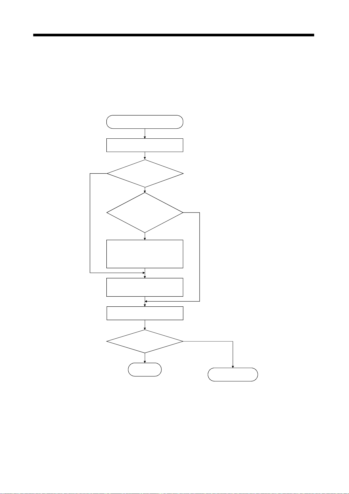
6. GENERAL GAIN ADJUSTMENT
6.2.3 Adjustment procedure by auto tuning
Since auto tuning is made valid before shipment from the factory, simply running the servo motor
automatically sets the optimum gains that match the machine. Merely changing the response level
setting value as required completes the adjustment. The adjustment procedure is as follows.
(1) Basic procedure
Auto tuning adjustment
Acceleration/deceleration repeated
Yes
Load inertia moment ratio
estimation value stable?
No
Auto tuning
conditions not satisfied.
(Estimation of load inertia
moment ratio is difficult)
Yes
Choose the auto tuning mode 2
(parameter No. 8: 0003) and set
the load inertia moment ratio
(parameter No. 12) manually.
Adjust response level setting
so that desired response is
achieved on vibration-free level.
Acceleration/deceleration repeated
Requested
performance satisfied?
No
No
END
Yes
To manual mode
6 - 6
Page 96

6. GENERAL GAIN ADJUSTMENT
6.2.4 Response level setting in auto tuning mode
Set the response (parameter No.9) of the whole servo system. As the response level setting is increased,
the trackability and settling time for a command decreases, but a too high re sponse level will generate
vibration. Hence, make setting until desired response is obtained within th e vibrati on-free range.
If the response level setting cannot be increased up to the desired response because of machine resonance
beyond 100Hz, adaptive vibration suppression control (parameter No. 25) or machine resonance
suppression filter (parameter No. 18) may be used to suppress machine resonance. Suppressing machine
resonance may allow the re spo nse lev e l set tin g to increase. Refer to Sect io n 7.2, 7.3 for adaptive vibra t io n
suppression control and machine resonance suppression filter.
Parameter No. 9
5000
Response level setting
Machine characteristic
Response level setting
1 Low 15Hz
2 20Hz
3 25Hz
4 30Hz
5 35Hz
6 45Hz
7 55Hz
8 Middle 70Hz
9 85Hz
A 105Hz
B 130Hz
C 160Hz
D 200Hz
E 240Hz
F High 300Hz
Machine rigidity
Machine resonance
frequency guideline
Guideline of corresponding machine
Large conveyor
Arm robot
General machine
tool conveyor
Precision
working
machine
Inserter
Mounter
Bonder
6 - 7
Page 97
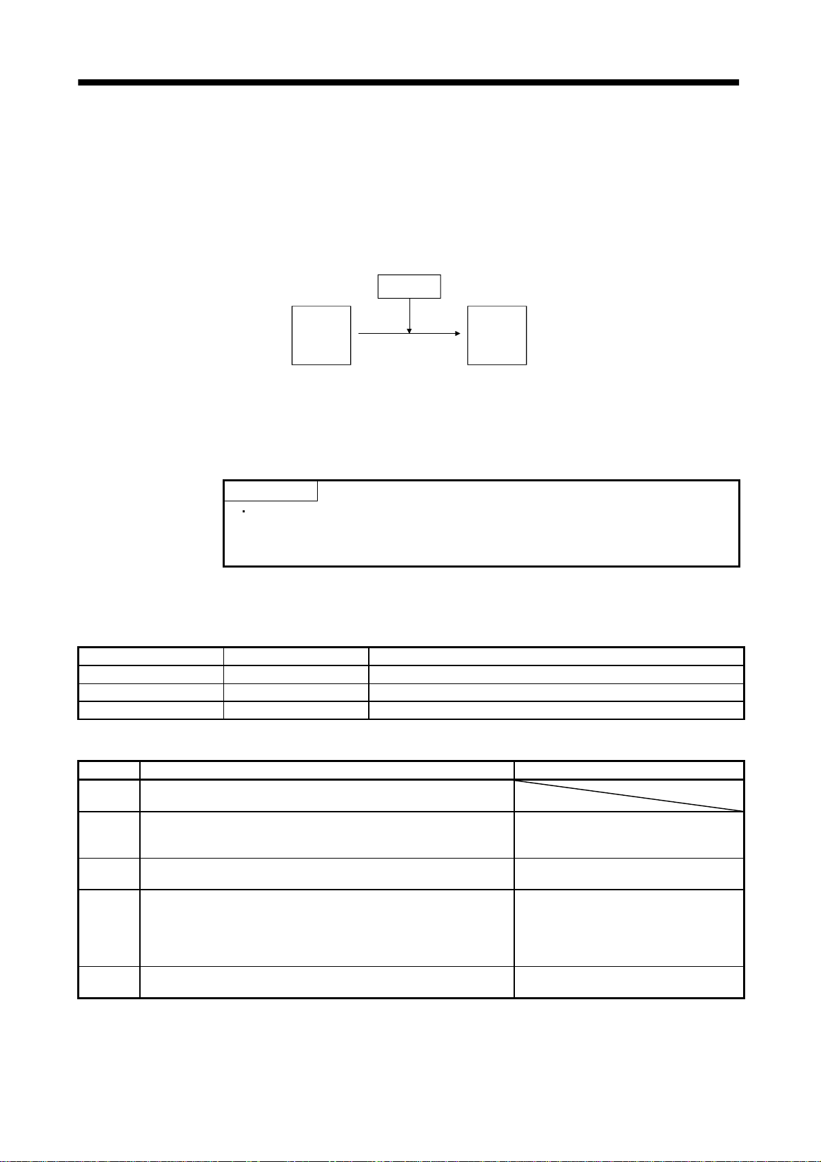
6. GENERAL GAIN ADJUSTMENT
6.3 Manual mode 1 (simple manual adjustment)
If you are not satisfied with the adjustment of auto tuning, you can make simple manual adjustment with
three parameters.
6.3.1 Operation of manual mode 1
In this mode, setting the three gains of po sition control gain 1 (PG1) , speed control gain 2 (VG2) and
speed integral compensation (VIC) automatically sets the other gains to the optimum values according to
these gains.
User setting
GD2
PG1
VG2
VIC
Automatic setting
PG2
VG1
Therefore, you can adjust the model adaptive control system in the same image as the general PI control
system (position gain, speed gain, speed integral time constant). Here, the position gain corresponds to
PG1, the speed gain to VG2 and the speed integral time constant to VIC. When making gain adjustment
in this mode, set the load inertia moment ratio (parameter No. 12) correctly.
6.3.2 Adjustment by manual mode 1 POINT
If machine resonance occurs, adaptive vibration suppression control
(parameter No. 25) or machine resonance suppression filter (parameter No.
18) may be used to suppress machine resonance. (Refer to Section 7.2, 7.3.)
(1) For speed control
(a) Parameters
The following parameters are used for gain adjustment:
Parameter No. Abbreviation Name
12 GD2 Ratio of load inertia moment to servo motor inertia moment
16 VG2 Speed control gain 2
17 VIC Speed integral compensation
(b) Adjustment procedure
Step Operation Description
Set an estimated value to the ratio of load inertia moment to servo
1
motor inertia moment (parameter No. 12).
Increase the speed control gain 2 (parameter No. 16) within the
2
vibration- and unusual noise-free range, and return slightly if vibration
takes place.
Decrease the speed integral compensation (parameter No. 17) within
3
the vibration-free range, and return slightly if vibration takes place.
If the gains cannot be increased due to mechanical system resonance or
the like and the desired response cannot be achieved, response may be
4
increased by suppressing resonance with adaptive vibration
suppression control or machine resonance suppression filter and then
executing steps 2 and 3.
While checking the settling characteristic and rotational status, fine-
5
adjust each gain.
Increase the speed control gain.
Decrease the time constant of the speed
integral compensation.
Suppressi on of machine res on a n ce
Refer to Section 7.2, 7.3.
Fine adjustment
6 - 8
Page 98

6. GENERAL GAIN ADJUSTMENT
(c) Adjustment description
1) Speed control gain 2 (parameter No. 16)
This parameter determines the response level of the speed control loop. Increasing this value
enhances response but a too high value will make the mechanical system liable to vibrate. The
actual response frequency of the speed loop is as indicated in the following expressi on:
Speed loop response frequency(Hz)
(1 ratio of load inertia moment to servo motor inertia moment)
Speed control gain setting
2) Speed integral compensation (parameter No. 17)
To eliminate stationary deviation against a command, the speed control loop is under
proportional integral control. For the speed integral compensation, set the time constant of this
integral control. Incre asing the setting lowers the response level. However, if the load inertia
moment ratio is large or the mechanical system has any vibratory element, the mechanical
system is liable to vibrate unless the setting is increased to some degree. The guideline is as
indicated in the following expression:
Speed integral
composition setting (ms)
Speed control gain 2 setting/ (1 ratio of load inertia moment
2000 to 3000
to servo motor inertia moment.)
(2) For position control
(a) Parameters
The following parameters are used for gain adjustment:
Parameter No. Abbreviation Name
12 GD2 Ratio of load inertia moment to servo motor inertia moment
13 PG1 Pos ition control gain 1
16 VG2 Speed control gain 2
17 VIC Speed integral compensation
2
(b) Adjustment procedure
Step Operation Description
Set an estimated value to the ratio of load inertia moment to servo
1
motor inertia moment (parameter No. 12).
Set a slightly smaller value to the position control gain 1 (parameter
2
No. 13).
Increase the speed control gain 2 (parameter No. 16) within the
3
vibration- and unusual noise-free range, and return slightly if vibration
takes place.
Decrease the speed integral compensation (parameter No. 17) within
4
the vibration-free range, and return slightly if vibration takes place.
5 Increase the position control gain 1 (parameter No. 13). Inc rease the position control gain.
If the gains cannot be increased due to mechanical system resonance or
the like and the desired response cannot be achieved, response may be
increased by suppressing resonance with adaptive vibration
6
suppression control or machine resonance suppression filter and then
executing steps 3 to 5.
While checking the settling characteristic and rotational status, fine-
7
adjust each gain.
Increase the speed control gain.
Decrease the time constant of the speed
integral compensation.
Suppressi on of machine res on a n ce
Refer to Section 7.2 and 7.3.
Fine adjustment
6 - 9
Page 99

6. GENERAL GAIN ADJUSTMENT
(c) Adjustment description
1) Position control gain 1 (parameter No. 13)
This parameter determines the response level of the position control loop. Increasing position
control gain 1 improves trackability to a position command but a too high value will make
overshooting liable to occur at the time of settling.
Position control
gain 1 guideline
2) Speed control gain 2 (parameter No. 16)
This parameter determines the response level of the speed control loop. Increasing this value
enhances response but a too high value will make the mechanical system liable to vibrate. The
actual response frequency of the speed loop is as indicated in the following expressi on:
(1 ratio of load inertia moment to servo motor inertia moment)
Speed control gain 2 setting
1
1
to
(
3
)
5
Speed loop response
frequency(Hz)
3) Speed integral compensation (parameter No. 17)
To eliminate stationary deviation against a command, the speed control loop is under
proportional integral control. For the speed integral compensation, set the time constant of this
integral control. Incre asing the setting lowers the response level. However, if the load inertia
moment ratio is large or the mechanical system has any vibratory element, the mechanical
system is liable to vibrate unless the setting is increased to some degree. The guideline is as
indicated in the following expression:
Speed integ ral
compensation setting(ms)
(1 ratio of load inertia moment to servo motor inertia moment)
Speed control gain 2 setting/ (1 ratio of load inertia moment to
Speed control gain 2 setting
2000 to 3000
servo motor inertia moment set value)
2
2
6 - 10
Page 100

6. GENERAL GAIN ADJUSTMENT
g
6.4 Interpolation mode
The interpolation mode is used to match the position control gains of the axes when performing the
interpolation operation of servo motors of two or more axes for an X-Y table or the like. In this mode, the
position control gain 1 and spe ed con trol ga in 1 whi ch dete rmine command trac kabili ty are se t man ually
and the other gain adjusting parameters are set automatically.
(1) Parameter
(a) Automatically adjusted parameters
The following parameters are automatical ly adjust ed by aut o tuning.
Parameter No. Abbreviation Name
12 GD2 Ratio of load inertia moment to servo motor inertia moment
15 PG2 Positio n c ontrol gain 2
16 VG2 Speed control gain 2
17 VIC Speed integral compensation
(b) Manually adjusted parameters
The following parameters are adjustable manually.
Parameter No. Abbreviation Name
13 PG1 Positio n c ontrol gain 1
14 VG1 Speed control gain 1
(2) Adjustment procedure
Step Operation Description
Choose the auto tuning mode 1 (parameter No. 8: 0001) and set the machine
1
resonance frequency of the response level to 15Hz 1 (parameter No. 9: 0001).
During operation, increase the response level setting (parameter No. 9), and
2
return the setting if vibration occurs.
Check the values of position control gain 1 (parameter No. 13) and speed control
3
gain 1 (parameter No. 14).
4 Choose the interpolation mode (parameter No. 8: 0000). Select the interpolation mode.
Using the position control gain 1 value checked in step 3 as the guideline of the
5
upper limit, set in position control gain 1 the value identical to the position loop
gain of the axis to be interpolated.
Using the speed control gain 1 value checked in step 3 as the guideline of the
6
upper limit, look at the rotation status and set in speed control gain 1 the value
three or more times greater than the position control gain 1 setting.
Looking at the interpolation characteristic and rotation status, fine-adjust the
7
gains and response level setting.
Select the auto tuning mode 1.
Adjustment in auto tuning mode
1.
Check the upper setting limits.
Set position control gain 1.
Set speed control gain 1.
Fine adjustment.
(3) Adjustment description
(a) Position control gain 1 (parameter No.13)
This parameter determines the response level of the position control loop. Increasing PG1 improves
trackability to a position command but a too high value will make overshooting liable to occur at
the time of settling. The droop pulse value is determined by the following expression.
Droop pulse value (pulse)
Rotation speed (r/min) 131,072(pulse)
Position control
ain 1 set value
(b) Speed control gain 1 (parameter No. 14)
Set the response level of the speed loop of the model. Make setting using the following expression
as a guideline.
Speed control gain 1 setting
Position control gain 1 setting 3
6 - 11
 Loading...