

Page 1
B2
Bass Module
Owner’s Guide
Guía de usario
Notice d’utilitsation
Page 2
B2 BASS MODULE
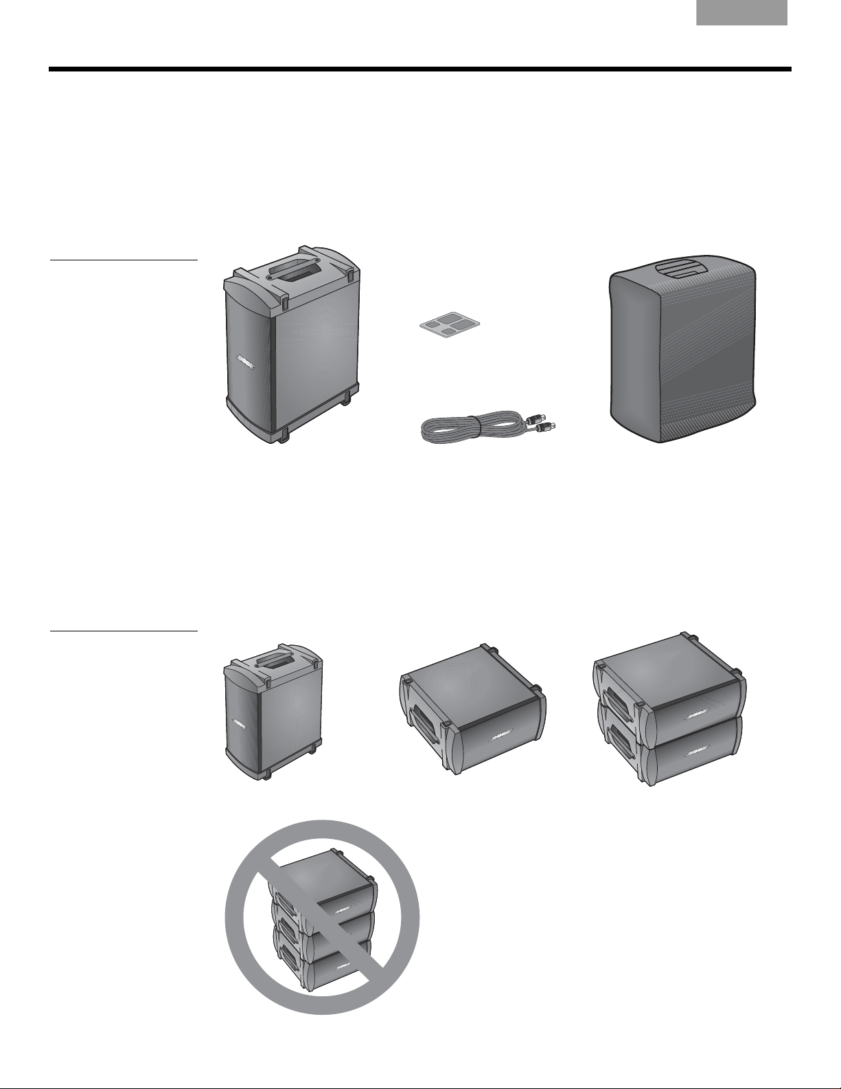
B2 bass module
B2 bass module
4-wire cable
Cover
Adhesive rubber
feet (4)
Stacked placement
Vertical placement
Horizontal Placement
Introduction
Thank you for purchasing the Bose® B2 bass module for your L1® model 1S or model II
system. The L1 power stand bass module output can adequately drive one B2 bass module.
A
second B2 bass module can be added (to your L1 model II system only) by using a Model
A1 PackLite power amplifier connected to the bass line output of the power stand.
Carefully unpack the carton and check for the items shown in Figure 1. Save all packing
materials, which provide the safest way to tra
damaged, do not attempt to use it. Notify Bose or your authorized Bose dealer immediately.
Figure 1
Carton contents
EnglishDeutschFrançais DanskEspañolItalianoSvenska Nederlands
nsport your system. If an item appears to be
For importanty safety information and more information on using the B2 module, please refer
to the owner’s guide that came with your L1 system, or visit www.Bose.com/livesound.
Positioning the B2 bass module
The B2 bass module can be placed vertically or horizontally on the floor next to the power
stand. When placed horizontally, you can build a stack of up to two modules (Figure 2).
Figure 2
B2 placement options
Do not stack more than two B2 bass modules.
2
Page 3

English Deutsch FrançaisDansk Español Italiano SvenskaNederlands
To power stand Bass Module Out
or PackLite amplifier OUTPUT
To PackLite amplifier OUTPUT
To power stand Bass Module Out
Connecting one B2 bass module
1. Plug one end of the B2 bass module cable into the B2 connector (Figure 3). Rotate the
plug clockwise to lock it in place. Listen for a soft click to ensure the connector is locked.
Figure 3
Bass module connections
2. Plug the other end of the cable into the Bass M
stand. Rotate the plug clockwise to lock it.
Note:
T o disconnect a B2 cable, slide back the metal tab on the body of the plug, rotate the plug
counterclockwise and pull it out of the conne cto r.
CAUTIONS:
• DO NOT connect any bass module other than the B2 or the B1 to the power stand.
• Use only the supplied B2 bass mod ule 4 -wire cab le t o co nnect the B2 bass mo dule to th e
p
ower stand. The power stand use s the signal s on t wo of t he w ires to aut omati cally sense
the state of the B2 bass module. DO NOT substitute the supplied cable with a 2-wire
speaker cable.
odule Out connector on the power
B2 B
ASS MODULE
Connecting a second B2 bass module (L1® model II system only)
Using a PackLite power amplifier model A1 allows you to add one additional B2 module to
your L1 model II system. Refer to the A1 Owner's Guide for detailed operating instructions.
Figure 4
Connections for two bass
modules
1. Make sure the A1 amplifier power s
2. Plug one end of the supplied ¼" TRS cable into the Bass-Line Out connector on the
po
wer stand. Plug the other end into the INPUT connector on the A1 amplifier.
3. Connect a B2 bass module cable from the OUTPUT connector on the A1 to a B2 bass
module.
4. Plug one end of the AC power cord into the A1 amplifier and plug the other end into an
AC (
mains) outlet.
5. Switch the A1 power
switch to ON (I).
witch is OFF.
3
Page 4

B2 BASS MODULE
Small
feet (2)
Large
feet (2)
B2 Rear Panel
Figure 5
Bass Level switch
EnglishDeutschFrançais DanskEspañolItalianoSvenska Nederlands
The B2 bass module includes a switch allowing you to select the appropriate level of bass
output for your application.
There are three settings:
=
+
Normal = Bass voicing ideal for bass guitar or live sound application when mic'ing
-
Bass voicing designed for DJ/Music playback applications
a kick drum
= Bass voicing which is perfect for acoustic guitar and vocal
Attention L1 Model II users: In order to take advantage of the B2 rear panel bass level
features you must upgrade your power stand firmware to version 1.4 or higher. If your power
stand firmware is not current, the rear panel switch must be in the Normal position. + or switch positions will not work. For the latest firmware please visit www.Bose.com/livesound.
Attention L1 model I and Classic users: When using the B2 with the L1 model I or
Classic systems the rear panel switch must be in the Normal position. + or - switch positions
will not work.
Attaching rubber feet
On smooth surfaces like wood floors, certain frequencies may cause the loudspeaker to
slide. For added stability and protection, detach the included self-adhesive rubber feet and
attach them to the loudspeaker in the four recesses (as shown in Figure 6). When using the
loudspeaker, keep the rubber feet in contact with the floor.
Figure 6
Attaching rubber feet
4
Page 5

English Deutsch FrançaisDansk Español Italiano SvenskaNederlands
Technical Information
Dimensions: 23.4''H x 13.31''W x 18.9''D (59.4 cm x 33.8 cm x 48 cm)
Weight:
Impedance: 4 o
This product conforms to all applicable EU directive requirements. The complete declaration
of conformity can be found at www.Bose.com/compliance.
PackLite is a registered trademark of Bose Corporation in the U.S. and/or other countries.
45 lb (20.41 kg)
hms
B2 B
ASS MODULE
5
Page 6

©2012 Bose Corporation, The Mountain
Framingham, MA 01701-9168 USA
AM365142 Rev.00
www.Bose.com/livesound
 Loading...