

Page 1

AV28 General Test Procedures
1. Initial Product Test
Note: Before taking the unit apart or performing any repair process, an attempt to verify the cus-
tomer complaint must be made.
1.1 Read any customer note included with the unit.
2. Attempt to verify the complaint before opening the unit or performing any repairs.
2.1 Customer complaint not verified, discuss with customer.
2.2 Customer complaint verified, troubleshoot and repair the unit. Refer to the AV28 Troubleshoot-
ing Tips/Preventative Repair Measures document.
®
3. Check the software revision of the unit. Refer to the Bose
http://serviceops.bose.com for information regarding the latest software revision.
3.1 With the system off and powered applied, press “Store” and “Enter”.
4. Verify Performance and all functions using the following procedures.
4.1 Tuner performance procedures.
service extranet site,
4.2 Input/Output performance procedures.
4.3 CD performance procedures.
4.4 User Interface Performance Verification.
Required Test Equipement and Cables
1. Audio Signal Generator.
2. Oscilliscope
3. Volt Meter
4. AM/FM Signal Generator.
5. AV28 remote control part number 256119-001.
6. PS28 or PS48 bass module with cubes (to test digital audio Zone ouputs).
7. AV28 test cable part number 264565.
8. RCA to bare wire cables (to connect cube speakers to bass module).
Rear cable part number 180644; black.
Left/Center/Right part number 180643-4; black.
Note: AC2 connector part number 195505-001 to connect bare wire to Jewel® Cube speaker.
9. Test CDs as listed below or equivalent.
Parameter Nominal Limit Suggested Test disc
Defect Tracking (void) 1.0 mm 0.8 mm Pierre Vernay, test CD#2
Defect Tracking (black dot) 1.0 mm 0.8 mm ABEX test disc TCD-725R
Defect Tracking (scratch) 1.6 mm 1.0 mm ABEX test disc TCD-721 R
Defect Tracking
(finger print)
Defect Tracking
(warped disc)
Defect Tracking
(eccentric disc)
75 mm 65 mm ABEX test disc TCD-725R
1.0 mm 0.7 mm ABEX test disc TCD-732RA
210 mm 140 mm ABEX test disc TCD-714R
1
Page 2
AV28 Performance Verification Procedures
AM Performance Tests
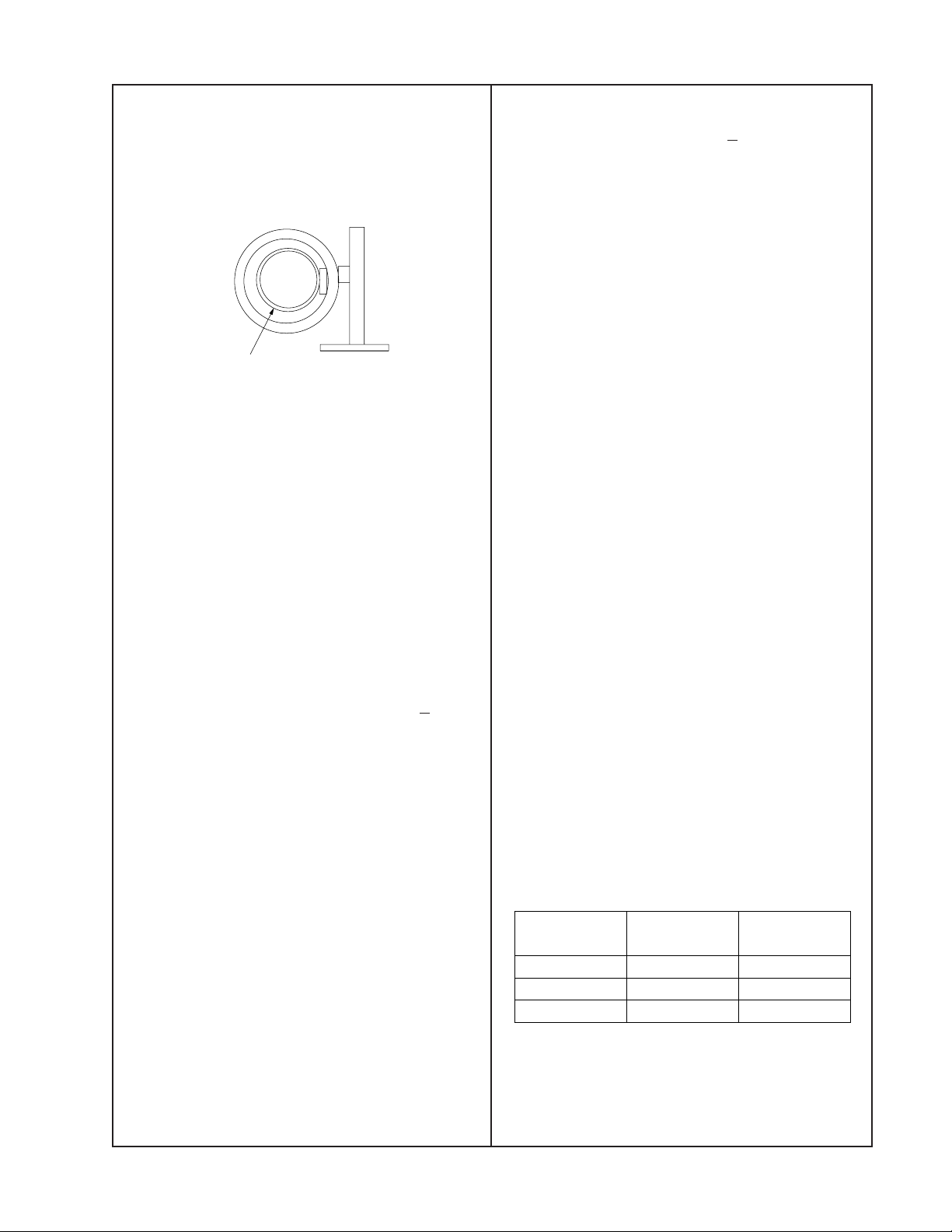
AM Tuner General Test Setup
Setup a loop antenna as shown.
Test Loop
External AM
Loop Antenna
positioned inside
test loop antenna
Figure 1. AM Test Setup
1. AM Sensitivity Test
1.1 Set the RF generator output to 70 dBuV/M,
30% AM modulation, 400Hz and the unit and
RF generator to 1080 kHz.
1.2 Reference a dB meter to the left or right line
level output.
3.2 Measure the distortion at the left or right
line level output. It should be < 3.0%.
4. FM Stop Level Test
4.1 Set the RF generator to 98.9 MHz, 1 kHz
mono modulation, pilot off, 75 kHz deviation, 36
dBuV/M, at the unit’s FM antenna input.
4.2 Place the unit into seek and verify that it
stops at 98.9 MHz.
4.3 Reduce the RF generator to 25 dBf.
4.4 Tune the unit to 98.1 MHz and then place
the unit into seek. Verify the radio does not stop
at 98.9 MHz.
5. Serial Data Verification
5.1 Connect an Oscilloscope to the serial data
output connector J704 pin 2.
5.2 Press volume up or down on the console.
Observe a digital wave form on the oscilloscope.
1.3 Turn off the RF generator’s modulation.
1.4 The line level output should measure < -20
dB, SNR.
2. AM Stop Level Test
2.1 Set the RF generator to 1130 kHz, AM
modulation, 400 Hz modulation, 65 dBuV/M.
2.2 Place the unit into seek and verify the unit
stops at 1130 kHz.
2.3 Switch the RF generator for a 55 dbuV/M
field intensity and verify the unit does not stop
at 1130 kHz.
3. FM Sensitivity Test
3.1 Set the RF generator to 98.1 MHz, 1 kHz
mono modulation, pilot off, 75 kHz deviation, 46
dBuV/M at the unit’s FM antenna input.
6. TV Sensor Verification
6.1 Apply a signal to the TV Sensor input J105
pin 2 at the level and frequency listed in the
following table. The signal should be applied to
the ring of a 3.5mm jack.
6.2 Measure the output of the detector, U303
pin 8, at J103 pin 19.
Note: Off <.8Vrms, On >2.5Vrms. Settling time
is .1 seconds to turn on, 2.0 seconds to turn
off.
Input
Frequency
Input
Amplitude
Detector
Output
60 Hz 200 mVrms <.8Vrms
15.75 kHz 30 mVrms >2.5 Vrms
31.5 kHz 30 mVrms >2.5Vrms
Note: If a unit fails any of these tests, refer to
the appropriate service manual for alignment
procedures. Replace any defective component
found.
2
Page 3

AV28 Performance Verification Procedures
5. Inputs/Outputs Verification
Test Functional test for
the...
Speaker Zones output,
1
TV S-Video, composite
video output, and DVD.
2 Analog audio Inputs
Digital (S/PDIF) and
3
optical audio inputs.
Record digital (S/PDIF)
audio output, Record
4
Optical output, Record
analog output and CD.
5 S-Video and Composite
video input
Connect the Media
Center...
Speaker Zones 1, 2
output...
TV S-video output... a TV S-Video input...
TV composite video
output...
TV analog audio
input...
VCR analog audio
input...
AUX analog audio
input...
Tape analog audio
input...
TV digital (S/PDIF)
audio input...
VCR digital (S/PDIF)
audio input...
AUX digital (S/PDIF)
audio input...
Tape digital
(S/PDIF) audio
input...
Optical input... the optical output of a
Record digital
(S/PDIF) output...
Record optical
output...
Record analog
output...
S-Video input... to the S-Video output of
Composite video
input...
To... and select the
an AM28/35 powered
speaker...
a TV composite video
input...
an analog source...
a digital (S/PDIF)
source...
source...
the digital (S/PDIF)
input of a device...
the optical input of a
device...
to the analog input of a
device...
a source...
to the Composite video
output of a source...
console
source...
DVD
(insert a DVD).
TV.
VCR.
AUX.
Tape.
TV.
VCR.
AUX.
Tape.
TV and assign
the optical input
to TV.
CD.
(insert a CD).
VCR. a clean
Listen/look for..
a clean
undistorted picture
from the TV. A
clean undistorted
audio output from
the PS28/35
powered speaker.
a clean
undistorted audio
output from the
PS28/35 powered
speaker
connected to the
console's Speaker
Zones output.
a clean
undistorted audio
output from the
PS28/35 powered
speaker
connected to the
console's Speaker
Zones output.
a clean
undistorted audio
output from the
source.
Sundistorted
output
from
the...
Video
output.
Compo
-site
video
output
Note:
1. The remote control is needed to turn on the Zone 2 output and should be used to verify the unit’s
ability to respond to remote commands. Refer to the Zone 2 Operation section on page 76.
6. CD Performance Test
6.1 The media center should be able to play the test discs listed in the following table.
Parameter Nominal Limit Suggested Test disc
Defect Tracking (void) 1.0 mm 0.8 mm Pierre Vernay, test CD#2
Defect Tracking (black dot) 1.0 mm 0.8 mm ABEX test disc TCD-725R
Defect Tracking (scratch) 1.6 mm 1.0 mm ABEX test disc TCD-721 R
Defect Tracking
(finger print)
Defect Tracking
(warped disc)
Defect Tracking
(eccentric disc)
75 um 65 um ABEX test disc TCD-725R
1.0 mm 0.7 mm ABEX test disc TCD-732RA
210 mm 140 mm ABEX test disc TCD-714R
3
Page 4

AV28 User Interface Performance Verification
7. User interface test
7.1 Press each button on the console keypad
and ensure its operation.
7.1.1 Press the On/Off button. Ensure the unit
turns on.
7.1.2 To ensure remote operation, select at
least one function (i.e. FM/AM) and ensure the
unit responds appropriately to the remote
control.
7.1.3 Press the volume up (/\) and down (\/)
button on the console keypad and ensure the
unit responds appropriately.
7.1.4 With the Radio tuned to a station, press
the Store button on the console keypad. The
display shows, STORE TO PRESET <number>? Press Store again or press Enter to
save the preset. The display shows “STATION
SAVED to <number>.
7.1.5 Using the remote tune to the preset
station you set in procedure 7.1.3. Press Erase
on the media center. The display shows,
ERASE PRESET <number>? Press Erase
again to delete the preset. The display shows,
PRESET <number> ERASED.
7.1.6 Press the Source button. Ensure, with
each press, the display cycles through the
various sources.
7.1.7 Press the Open/Close button. Ensure the
DVD/CD drawer opens and then press it once
more to shut the drawer.
7.1.8 Press the All Off button. Ensure the unit
shuts off.
4
 Loading...