

Page 1

The Bose® Acoustimass® - 6 Home Theater Speaker
System
Owner’ s Guide
December 20, 2001
AM189815_04_V.pdf
Page 2

Introduction
Thank you
We appreciate your choice of the Bose® Acoustimass®-6 home theater speaker system. With
these Virtually Invisible® speakers you will surround yourself with realistic sound, without a
lot of equipment.
For your records
The serial number is located near the connection panel on the Acoustimass module.
Serial number: _________________________________________________________________
Dealer name: __________________________________________________________________
Dealer phone: _______________________ Purchase date: ___________________________
We suggest you keep your sales slip and warranty card together with this owner’s guide.
Declaration
of Conformity
We, the offerer:
Bose® Corporation, The Mountain
Framingham, MA 01701-9168 USA
acknowledge our sole responsibility, that the product:
Kind of equipment: Loudspeakers
Type designation: Acoustimass® -6
Home Theater Speakers
in accordance with EMC Directive 89/336/EEC and Article 10(1) of the Directive,
is in compliance with the following norm(s) or document(s):
Technical regulations: EN50081-1, EN50082-1
Accredited by Bose Corporation
21 February 1997
Bose B.V., Nijverheidstraat 8 Anton Schalkamp
1135 GE Edam, General Manager, Bose Europe
The Netherlands Manufacturer’s authorized EU representative
2 December 20, 2001 AM189815_04_V.pdf
Page 3

Where to find...
Setting Up
Before you begin ........................................................................................................4
Unpack the carton ...................................................................................................... 5
Placing your Acoustimass®-6 speakers to achieve realistic home theater sound ......6
Select the locations for your speakers .......................................................................7
Left and right front cube speakers ......................................................................7
Center cube speaker ........................................................................................... 8
Surround cube speakers ..................................................................................... 8
Acoustimass module ........................................................................................... 9
Connect the speakers .............................................................................................. 10
Connect the Acoustimass module to the center and front cube speakers ...... 10
Connect the module to the surround cube speakers ....................................... 11
Connect the module to the receiver .................................................................. 11
Check the connections ..................................................................................... 12
Attach the module end cover, if needed ........................................................... 13
Using Your Acoustimass-6 Speakers
For realistic home theater sound .............................................................................. 14
How to set your Pro-Logic receiver .................................................................. 14
How to set your Dolby Digital (AC-3) receiver................................................... 14
Contents
Maintaining Your Acoustimass-6 Speakers
Troubleshooting........................................................................................................ 15
Cleaning the speakers .............................................................................................. 15
Product Information
Warranty period ........................................................................................................ 16
Technical information ...............................................................................................16
Accessories ..............................................................................................................17
Bose® Corporation ................................................................................. inside back cover
AM189815_04_V .pdf December 20, 2001 3
Page 4

Setting Up
Before you begin
Bose® Virtually Invisible® speaker technology allows you to enjoy lifelike home performances
from the very latest surround sound encoded movies, CDs, and television shows, without a
room full of speakers.
Your video sound source (stereo VCR, laserdisc or digital video player, or stereo television)
sends the encoded program material to the surround sound receiver, which interprets it by
distributing various sounds to particular speakers. Although the sound mix varies with
different types of programs, dialogue is usually sent to the center speaker while sounds
from the left or right side of the picture go to the left or right front speakers. Ambient sounds
and special effects are directed to one or both of the surround (rear) speakers. The unique,
easy-to-hide Acoustimass® module delivers bass for all channels. At any point in a surround
sound performance, you may hear sound from all or just a few of the speakers, but the
overall experience puts you in the center of the action.
To select surround-encoded program material, look for any of the terms Surround, Dolby
Surround, and the double-D symbol
word “surround” preceding a TV broadcast. Your Acoustimass-6 home theater speakers are
also compatible with Dolby Digital (AC-3) receivers and program material. The special
settings for Dolby Digital are described on page 14.
You can also enjoy a wide variety of stereo programming that is not surround-encoded with
your Acoustimass-6 speakers. Simply adjust your receiver as described on page 14.
*Dolby and the double-D symbol are trademarks of Dolby Laboratories Licensing Corporation.
* on tapes and discs, and the
4 December 20, 2001 AM189815_04_V.pdf
Page 5
Setting Up
Unpack the carton
• Remove any staples from the opened carton flaps.
• Lift out the two brown inner cartons.
• Remove the five cube speakers from their packaging.
®
• Remove the Acoustimass
• Gently roll the carton over onto its side and then onto its opening.
• Carefully lift the carton from around the Acoustimass module and packing cushions.
• Do not detach the removable cables connected to the Acoustimass module.
• If the speakers or the Acoustimass module appear damaged, do not use them. Repack
everything in the original carton and contact your authorized Bose
Note:
Now is a good time to record the serial number of these speakers on page 2 of this
guide and on your warranty card. It is a good idea to save all packing materials for possible
future use.
Module
Rubber feet
end cover
module end cover from its packaging.
Cables
Acoustimass
module
Quick set up guide
Owner’s guide
®
dealer immediately.
Cube speakers
WARNING:
The Acoustimass module
weighs 19 pounds (8.6 kg).
Use good lifting practice to
avoid injury.
To avoid danger of suffocation, keep the plastic bags
that wrap these speakers out
of the reach of children.
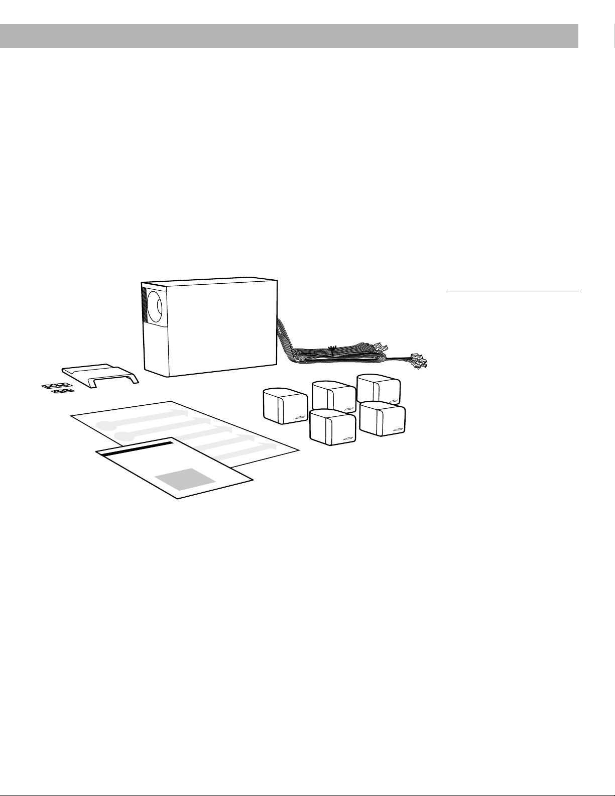
Figure 1
What comes in the carton:
• Acoustimass module
• Module end cover
•5 cube speakers
• 20' (6 m) speaker input cable
• 20' (6 m) front speaker output
cable
• 50' (15 m) rear speaker output
cable
• 8 protective rubber feet
• Owner’s guide
• Quick set up guide
Setting Up
AM189815_04_V .pdf December 20, 2001 5
Page 6
Setting Up
Placing your Acoustimass®-6 speakers to achieve
realistic home theater sound
The center speaker localizes action and dialogue on your screen. Sound from the center
speaker should seem to come from within the picture.
The left and right front speakers create a sound image wider than the screen that seems
natural to viewers sitting anywhere in the room.
The surround speakers add subtle sounds and special effects that expand the visual image,
bringing the viewer into the center of the action. The surround speakers should be positioned to allow the sound to reach the viewer from both sides, rather than from directly
behind.
You can place the front and center speakers near a TV screen with no picture interference,
because all of the cube speakers are magnetically shielded.
The Acoustimass module is not magnetically shielded and should be at least 2 feet (60 cm)
from your screen, but at the same end of the room as the front and center speakers. Bose
Acoustimass speaker technology takes advantage of the fact that the source of bass sound
is difficult to locate, so you can hide the Acoustimass module conveniently out of sight.
Placing it near a corner increases bass output from the module.
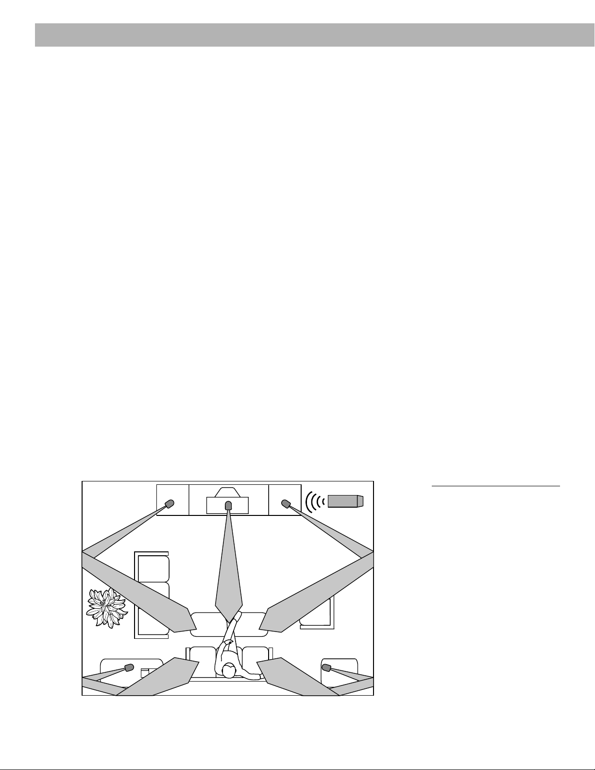
A suggested home theater layout that conforms to the guidelines described above is shown
in Figure 2.
You may choose to place the speakers differently, to take advantage of the sound characteristics of different rooms. For instance, where walls are absent or the room is large, you
may prefer not to angle the left and right speakers as shown. You can experiment to find the
best position.
Your speakers come with sufficient cable lengths to allow you to have the following distances between components:
• Up to 20 feet (6 m) between the Acoustimass module and the receiver.
• Up to 20 feet (6 m) between the Acoustimass module and the front and center cube
speakers.
• Up to 50 feet (15 m) between the Acoustimass module and the surround speakers.
®
Left
Left surround Right surround
6 December 20, 2001 AM189815_04_V.pdf
Center
Right
Figure 2
One suggested home theater
layout
Page 7

Select the locations for your speakers
L/R
The lengths of cable supplied with your Acoustimass®-6 system provide a great deal of
flexibility in speaker placement. Optional Bose® extension cable, add-on connectors, wall
brackets, and floor stands can add to your choices. See “Accessories” on page 17.
Setting Up
Left and right front cube speakers
Use the two cube speakers with black terminals that are marked L/R (Figure 3). There are
several ways to achieve an accurate left and right sound image (Figure 4).
• Place the front speakers on either side of your TV, at least 6 feet (2 m), or as much as 15
feet (5 m) apart.
• Place them in line with the center of the screen for the best sound balance (position 1).
Placing them in a line above the top of the TV is another choice (position 2).
• Aim the speakers inward for more accurate imaging or outward for a more spacious
effect. Adjust them according to your preference.
• The speaker on the left as you face the TV connects to the LEFT FRONT jack on the
Acoustimass module.
2 2
1
1
Figure 3
The terminal on the back of a left
or right front cube speaker
L/R
Figure 4
Suggested choices for left and
right front speaker placement
AM189815_04_V .pdf December 20, 2001 7
Page 8

Setting Up
C
/S
Center cube speaker
Select one speaker with a gray terminal marked C/S as the front center speaker (Figure 5).
Sound from the center speaker should seem to come from within the picture.
Figure 6 shows suggested positions for the center speaker.
• Place the center cube speaker above, below, or on top of your television. If below, be
sure that the cube speaker is not supporting the weight of the television in any way.
• Aim this speaker straight ahead for onscreen imaging.
• Keep it as close to the vertical center of the screen as possible, for the most accurate
dialogue reproduction (positions 1 or 2).
1
2
Note:
inside back cover), and ask for Part Number 178321-04.
To obtain additional rubber feet, free, call Bose® Customer Service (listed on the
Figure 5
The terminal on the back of a
center or surround cube speaker
C/S
Figure 6
Suggested choices for center
speaker placement
CAUTION:
the center speaker on top of a
television, attach the four
small rubber feet to its bottom
surface. They give added
stability on slippery surfaces,
such as polished furniture,
marble, or glass.
Before placing
Surround cube speakers
The remaining two speakers with gray terminals marked C/S are the surround speakers.
Their left and right rear channel sound should reach the viewer from both sides, rather than
from directly behind (Figure 7).
• Put one on the left and the other on the right, beside or just to the rear of the home
theater seating area.
• Position them so they do not create a direct sound path to the ears of the listeners
(position 1).
• Generally aim them away from the viewers, toward the rear or side walls (positions 2
or 3).
• If you want these speakers directly behind the seating area, make sure they are not
directed at the viewers.
• The rear speaker to your left as you face the TV connects to the LEFT SURROUND jack
on the Acoustimass® module.
8 December 20, 2001 AM189815_04_V.pdf
Page 9

Setting Up
Figure 7
Suggested choices for surround
(rear) speaker placement
1
2
3
1
2
3
Acoustimass® module
Bose® recommends putting your Acoustimass module at the same end of the room as the
television monitor. To prevent interference, keep the module at least 2 feet (60 cm) from the
television.
• You may hide the Acoustimass module behind or under furniture, but do not block the
opening. Be sure there is at least 2 inches (5 cm) between the opening and any surface.
• Placing the module close to a corner increases the bass output. Moving it toward the
center of the wall reduces the output.
• If the opening faces the wall, it further increases the bass. If it faces away, it decreases
the bass. For the most bass response, place the opening 2 to 3 inches (5 to 8 cm) from
a wall or corner.
• Stand the module vertically or horizontally (Figure 8). Attach the large set of rubber feet
to the bottom surface. If you plan to stand the module on the cable connection end,
do not use the module end cover, but be sure to attach the large rubber feet to protect
the connections.
Module end
cover
Rubber
feet
Rubber
feet
AM189815_04_V .pdf December 20, 2001 9
Figure 8
Acoustimass module positions
Page 10

Setting Up
L/R
C/S
L/R
Connect the speakers
Note:
The supplied cables make it easy for you to connect your system. Each cable connector is
colored gray or black and embossed with a letter to identify the cube speaker, the output, or
the input it matches. The connections at the Acoustimass® module are already made for you.
There are three sets of cables, joined together to form ribbons, which may be separated or
“unzipped” as needed to comfortably reach the speakers (Figure 9). Separate the cables as
you are laying out the cable lengths. However, you may want to keep the unextended length
of cable joined, making it easier to hide.
• The 20 foot (6 m) cable with three pairs of wires connects the Acoustimass module to the
• The 50 foot (15 m) cable with two pairs of wires connects the Acoustimass module to the
• The 20 foot (6 m) cable with five pairs of wires connects the Acoustimass module to the
Note:
to splice the supplied cables for any other reason, inquire about the add-on connectors and
extension cable available from Bose® Customer Service. Refer to page 17 for details on
these accessories. Bose Customer Service telephone numbers are listed on the inside back
cover.
You can refer to Figure 12 on page 12 for an overview of the completed connections.
center, left front, and right front cube speakers.
left and right surround cube speakers.
outputs on the receiver. Separate these wires just enough to reach the connectors.
If you have already installed cable behind walls or under floors, or believe you need
CAUTION:
Before making any connections turn off your receiver or
amplifier and unplug it from
the outlet (AC power mains).
Not doing so may result in
damage to your system.
Figure 9
Separating cables
CAUTION:
Never use broken or frayed
wiring, which can result in
electrical shock or damage to
your system.
The supplied cables are not
intended for in-wall installation.
Connect the Acoustimass module to the center and front cube
speakers
Use the 20 foot (6 m) cable with three pairs of
wires to connect the Acoustimass module to
the center and front cube speakers. Just
press the custom connectors into place.
• The gray connector goes into the gray
terminal on the center speaker (Figure 10).
C
• The black connector marked L goes into
the black terminal on the left front speaker
(to the left of the TV as you face it).
• The black connector marked R goes
into the black terminal on the right front
speaker.
10 December 20, 2001 AM189815_04_V.pdf
Figure 10
Inserting gray connector marked
C into the gray terminal marked
C/S
CAUTION:
Never connect the cubes
directly to the receiver. Always
connect the cube speakers to
the Acoustimass module, then
connect the Acoustimass
module to the receiver.
Page 11

At the Acoustimass® module, check to be sure the connectors are firmly inserted into the
proper OUTPUT TO CUBE SPEAKER jacks.
• The black L connector goes into the L jack.
• The gray C connector goes into the C jack.
• The black R connector goes into the R jack.
Connect the module to the surround cube speakers
Use the 50 foot (15 m) cable with gray connectors to join the Acoustimass module to the
surround speakers.
• The gray connector marked LS goes into the gray terminal on the left surround speaker
(to your left as you face the TV).
• The gray connector marked RS goes into the gray terminal on the right surround
speaker.
At the Acoustimass module, make sure the gray connectors are firmly inserted into the LS
and RS OUTPUT TO CUBE SPEAKER jacks.
Setting Up
Connect the module to the receiver
Use the 20 foot (6 m) cable with five wire pairs to connect the Acoustimass module to your
surround sound receiver.
1. Connect all wires to the receiver in phase (+ to + and – to –).
a. Connect each wire marked with a red collar (+) to the appropriate red (+) output.
b. Connect each plain wire (–) to the appropriate black (–) output.
2. Match the label on the red collar of each wire pair to the SPEAKER OUTPUT label on
the receiver:
a. LEFT wires go to the LEFT FRONT SPEAKER OUTPUT connections.
b. CENTER wires go to the CENTER SPEAKER OUTPUT connections.
c. RIGHT wires go to the RIGHT FRONT SPEAKER OUTPUT connections.
d. LEFT SURROUND wires go to the LEFT SURROUND (rear) SPEAKER OUTPUT
connections.
e. RIGHT SURROUND wires go to the RIGHT SURROUND (rear) SPEAKER OUTPUT
connections.
3. At the Acoustimass module, check to make sure all connectors are firmly inserted into
the proper INPUT FROM RECEIVER OR AMPLIFIER jacks. Black connectors go into L
and R jacks. Gray connectors go into C, LS, and RS jacks.
CAUTION:
Do not connect the Acoustimass module directly to your
television unless the television
provides surround decoding
circuitry and amplified outputs
for all channels.
AM189815_04_V .pdf December 20, 2001 11
Page 12

Setting Up
Check the connections
Check all connections from the receiver to the Acoustimass® module and the module to the
cube speakers, making sure the two speakers with black terminals are connected as front
speakers (Figure 11). Check to be sure all speakers are connected to the proper terminals
according to their position in your room (Figure 12).
At the receiver, make sure the wires are connected in phase (+ to + and – to –). Incorrect
wiring can result in a total loss of Acoustimass module output.
Be sure to correct any wiring problems before you plug your receiver in and turn it on.
RCL
Figure 11
Black connector and terminal
marked L/R on both the front left
and front right speakers
L/R
Figure 12
Completed connections
FRONT SPEAKERS
R
SURROUND SPEAKERS
L
L REAR R CENTER
RS LS
OUTPUTS
TO CUBE SPEAKERS
LCRLSRS
LEFT CENTER RIGHT LEFT RIGHT
LCRLSRS
SURROUND SURROUND
INPUTS
FROM RECEIVER OR AMPLIFIER
CAUTION:
Do not allow exposed wires to
brush against each other; this
could damage your receiver.
12 December 20, 2001 AM189815_04_V.pdf
Page 13

Attach the module end cover , if needed
The module end cover is designed to hide the cabling and extend the smooth, clean lines of
the Acoustimass® module. However, because the cover has a beveled surface, you cannot
stand the module on that end with the cover in place.
If you plan to use the cover, attach it to the cable end after all connections have been
checked (Figure 13). Gently push the end cover into the grommets on the Acoustimass
module.
Your set up is complete. Enjoy your Acoustimass-6 speaker system.
Setting Up
Figure 13
The module end cover fits over
the cables
AM189815_04_V .pdf December 20, 2001 13
Page 14

6
7
8
9
10
11
12
13
141516
17
18
19
21
20
22
23
24
25
26
27
28
29
30
5
4
3
2
1
0
Using Y our Acoustimass®-6 Speakers
For realistic home theater sound
Each speaker produces only the sound directed to it by the steering logic in your surround
sound receiver. During a surround sound program, the front and center speakers will emit
sound almost constantly, while the surround speakers may be silent for periods of time.
How to set your Pro-Logic receiver
For use in video applications, be sure the SURROUND SOUND center mode setting of your
receiver is on NORMAL (Figure 14). You may press in the button labeled Loudness (Bass
Boost or Super Bass on some receivers) to see if you prefer that video sound.
Use the test tone on your receiver to further verify connections and to adjust the volume
level of the speakers.
T o use the test tone
1. Press test tone ON at the remote.
2. Listen and confirm that each speaker reproduces sound as the tone moves from speaker
to speaker in this order: LEFT, CENTER, RIGHT, SURROUND. One tone should come
from both SURROUND speakers at the same time.
3. Adjust the volume levels of the CENTER and SURROUND speakers to achieve the
balance you prefer for your listening area.
Instructions for this process vary, depending on the brand and model of receiver you are
using. Follow your receiver owner’s guide instructions for more details on using the test tone.
T o balance the bass and treble
Upholstered furniture, wall-to-wall carpets, or heavy drapes can muffle treble (high notes),
making your speaker system sound bass heavy. Bare floors and walls and hard surface
furniture can make your speaker system sound too shrill. After listening to your speakers,
you may want to adjust the balance of bass and treble. You can use the bass and treble
controls on your receiver.
Figure 14
A Dolby Pro-Logic receiver set for
NORMAL center mode
Suggestion for spacious stereo sound
Try setting your receiver to the PHANTOM surround mode while listening to music from a CD
or cassette tape. This will enable you to enjoy a wide stereo image reproduced by the front
speakers, plus the ambience and spaciousness provided by your surround speakers.
If your receiver has a Loudness button, turn that off during regular stereo playback.
How to set your Dolby Digital (AC-3) receiver
Your Acoustimass-6 speakers are compatible with the output from Dolby Digital (AC-3)
receivers. Take special care to set the channel output according to the specifications listed in
the chart below. The Acoustimass speaker system is a full-range system and must be set as
LARGE speakers on the Dolby Digital screen menu. An exception is the center speaker,
which must be set as SMALL. Turn the subwoofer OFF. Finally, turn the LFE (low-frequency
effects) ON and set the crossover frequency to 200 Hz.
Receiver channel output Proper setting
Left and Right Front ............................................ LARGE
Center ................................................................. SMALL
Left and Right Surround ..................................... LARGE
Subwoofer ............................................................. OFF
LFE (low-frequency effects) .................................... ON
Crossover frequency ........................................... 200 Hz
Follow the receiver owner’s guide instructions for using the receiver test tone to verify your
connections and to adjust the volume levels of the speakers.
14 December 20, 2001 AM189815_04_V.pdf
Page 15

Maintaining Y our Acoustimass®-6 Speakers
Troubleshooting
If you have a problem with your Acoustimass-6 speakers, turn off your sound source and try
the solutions below. If you still have a problem, contact your Bose® dealer to arrange for
service. Or, to contact Bose directly, refer to the inside back cover of this guide.
Problem What to do
System does not
function at all
No sound
No surround sound
Sound is distorted • Make sure speaker cable is not damaged.
• Make sure the power cord of the receiver is plugged into an
operating AC wall outlet and the receiver is turned on.
• Be sure to select a source at the receiver (video, CD, tuner).
• Check the cube speaker and Acoustimass module connections.
Turn ON receiver.
• Check connections of external components to the receiver.
• Increase the volume.
• Disconnect any headphones.
• If your surround sound receiver is Pro-Logic, be sure your
receiver is connected to a stereo sound source (TV, VCR,
laserdisc or DSS player) by an RCA stereo cable. If the receiver
is connected directly to a stereo television, make sure that all
other program sources (VCR, laserdisc or DSS player) are
connected to the TV using RCA stereo cable as well.
• If your surround sound receiver is Dolby Digital (AC-3), be sure
the sound source (DSS, laser disc or DVD player) is connected
directly to your receiver as described in your receiver owner’s
guide.
• Reduce the volume of any external components connected to
the receiver.
No bass
Not enough or too
much bass
• Make sure the speaker connections at the receiver or amplifier
are correct (+ to + and – to –).
• If you are using the Dolby Pro-Logic mode, make sure surround
sound is turned ON.
• If you are using Dolby Digital (AC-3) programming, verify that
the settings are correct at the receiver. Also, be sure the source
material (laser disc or broadcast programming) is Dolby Digital
or AC-3 encoded.
• Move the Acoustimass module closer to a wall or corner to
increase bass. Move it farther from a wall or corner to decrease
bass. Or adjust the bass/treble control on the receiver slightly.
Cleaning the speakers
Wipe the cube speakers using a damp cloth. Do not use solvents or chemicals. Do not
allow liquids to spill on or objects to drop into the Acoustimass module or the speaker
grilles. You may vacuum the grilles carefully; the drivers are directly behind the grille cloth.
No other maintenance is needed.
AM189815_04_V .pdf December 20, 2001 15
Page 16

Product Information
Warranty period
Bose® Acoustimass®-6 speakers are covered by a limited 5-year transferable warranty.
Details of the coverage are explained on the warranty card packed with your speakers.
Please fill out the information section on your card. The serial number is located on the
Acoustimass module; you may choose to record it on page 2 of this guide. Then, please
detach and mail the card to Bose in the pre-addressed envelope.
Bose will try to remedy any problem within the terms of your limited warranty.
T echnical information
Features
• Acoustimass speaker technology combined with Adaptive Energy SummingTM speaker
design
• Virtually Invisible® speaker design
• Magnetically shielded cube speakers
• Automatic system protection circuitry
• Syncom® computer quality control
Speaker driver complement
Cube speakers: one 21⁄2" (6.3 cm) TwiddlerTM speaker
Acoustimass module: two dual-voice coil 51⁄4" (13.3 cm) woofers for front and surround
channels
Connectivity
Compatible with A/V receivers rated from 10 to 100 watts per channel; rated from 4 to 8
ohms
Finish
Cube speakers: Black or Arctic white finish
Acoustimass module: Scratch-resistant black or Arctic white textured finish
Size/Weight
Cube speakers: 31⁄8"H x 3"W x 43⁄4"D (7.9 cm x 7.6 cm x 12.2 cm)
1.1 lb (.5 kg)
Acoustimass module: 14"H x 71⁄2"W x 161⁄2"D (35.5 cm x 19 cm x 41.9 cm)
19 lb (8.6 kg)
Packed system: 205⁄8"H x 111⁄8"W x 241⁄2 "D (52.3 cm x 28.2 cm x 62.2 cm)
36 lb (16.4 kg)
16 December 20, 2001 AM189815_04_V.pdf
Page 17

Product Information
Accessories
Add-on connector: PN189830 (shown)
Adapts other speaker cable for use
with Acoustimass®-6 speakers
Extension cable: PN187092-1 (black), PN187092-2 (white)
50' (15 m) ribbon with five pairs of wire
Floor stands: UFS-20B (black), UFS-20W (white)
Wall brackets: UB-20B (black), UB-20W (white)
Note:
Both UFS-20 floor stands and UB-20 wall brackets fit
Acoustimass-6 cube speakers. However, before attaching a
stand or a bracket, it is necessary to change the orientation
of the cable connector. Turn the connector upside down
before inserting it into the terminal on the back of the cube
speaker. When it is correctly attached for use with a floor
stand or bracket, the cable will run up rather than down
from the cube speaker.
For more information, or to purchase accessories, contact
your authorized Bose® dealer. Or, to call Bose directly, refer to the Bose Customer Service
telephone numbers listed on the inside back cover.
Cable
Figure 15
Add-on connector for use with
speaker wire
Figure 16
Cable connector properly
attached to cube speaker for use
with bracket or stand
AM189815_04_V .pdf December 20, 2001 17
Page 18

Page 19

Bose® Corporation
USA
Bose Corporation, The Mountain
Framingham, MA 01701-9168
1-800-367-4008
Phone hours - ET (eastern time):
Weekdays 9 a.m. to 8 p.m.
Saturdays 9 a.m. to 3 p.m.
Canada
Bose Ltd., 1-35 East Beaver Creek Road
Richmond Hill, Ontario L4B 1B3
1-800-465-2673
Phone hours - ET (eastern time):
Weekdays 9 a.m. to 5 p.m.
European Office
Bose Products B.V., Nijverheidstraat 8
1135 GE Edam, Nederland
TEL 0299-390111 FAX 0299-390114
Australia
Bose Australia, Inc., 1 Sorrell Street
Parramatta, N.S.W. 2150
TEL 02 204-6111 FAX 02 204-6122
Belgique/België
Bose N.V., Limesweg 2, B-3700 Tongeren
TEL 012-390800 FAX 012-390840
Danmark
Bose A/S, Industrivej 7, 2605 Brøndby
TEL 4343-7777 FAX 4343-7818
Deutschland
Bose GmbH, Max-Planck-Straße 36d
D-61381 Friedrichsdorf
TEL 06172-71040 FAX 06172-710419
France
Bose S.A., 6, rue Saint Vincent
78100 Saint Germain en Laye
TEL 01-30616363 FAX 01-30614105
Italia
Bose S.p.A., Via della Magliana 876
00148 Roma
TEL 06-65670802 FAX 06-65680167
Japan
Bose K.K., Shibuya YT Building
28-3 Maruyama-cho
Shibuya-ku, Tokyo 150
TEL 3-5489-0955 FAX 3-5489-0592
Nederland
Bose B.V., Nijverheidstraat 8
1135 GE Edam
TEL 0299-390111 FAX 0299-390109
Norge
Bose A/S, Solheimsgate 11
N-2001, Lillestrøm
TEL 63-817380 FAX 63-810819
Österreich
Bose Ges.m.b.H., Vienna Business Park
Wienerbergstrasse 7 (10.OG)
A-1100 Vienna
TEL 01-60404340 FAX 01-604043423
Schweiz
Bose AG, Rünenbergerstrasse 13
4460-Gelterkinden
TEL 061-9815544 FAX 061-9815502
Sverige
Bose A/S, JohanneFredsgatan 4
S-43153 Mölndal
TEL 31-878850 FAX 31-274891
United Kingdom
Bose Limited, Unit G2
Trinity Trading Estate
Sittingbourne, Kent ME10 2PD
TEL 01795-475341 FAX 01795-427227
India
Bose Corporation India Private Limited
W-16, Greater Kailash-II
New Delhi 110 048
TEL (011) 648 4462 FAX (011) 648 4463
Ireland
Bose Corporation
Carrickmacross, Co Monaghan
TEL 042-61988 FAX 042-61998
From other locations
Bose Customer Service, 1 New York Ave.
Framingham, MA 01701-9168 USA
TEL (508) 766-1900 FAX (508) 766-1919
World Wide Web
www.bose.com
Page 20

©1999 Bose Corporation, The Mountain
Framingham, MA 01701-9168 USA
189815 AM Rev.04 JN97846
 Loading...