

Page 1

The Bose® Acoustimass® 5 and 20 Powered Speaker
System
Owner’ s Guide
December 20, 2001
AM262838_00_V.pdf
Page 2
Safety/Maintenance Information
WARNING:
To reduce the risk of fire or electric shock, do not expose the system to rain or
moisture.
CAUTION AVIS
RISK OF ELECTRICAL SHOCK
DO NOT OPEN
CAUTION: TO REDUCE THE RISK OF ELECTRIC SHOCK,
DO NOT REMOVE COVER (OR BACK).
NO USER-SERVICEABLE PARTS INSIDE.
REFER SERVICING TO QUALIFIED PERSONNEL.
.
These CAUTION marks are located on the bottom of your Lifestyle® Acoustimass
module:
The lightning flash with arrowhead symbol, within an equilateral triangle, is intended to alert
the user to the presence of uninsulated dangerous voltage within the system enclosure that
may be of sufficient magnitude to constitute a risk of electric shock.
The exclamation point within an equilateral triangle, as marked on the system, is intended to
alert the user to the presence of important operating and maintenance instructions in this
owner’s guide.
RISQUE D’ÉLECTROCUTION
NE PAS OUVRIR.
ATTENTION : POUR RÉDUIRE LE RISQUE D’ÉLECTROCUTION,
NE RETIREZ PAS LE COUVERCLE (NI LE PANNEAU ARRIÈRE).
IL NE SE TROUVE À L’INTÉRIEUR AUCUNE PIÈCE POUVANT
ÊTRE RÉPARÉE PAR L’USAGER. ADRESSEZ-VOUS A UN
À UN RÉPARATEUR COMPÉTENT.
®
Additional safety information
See the additional instructions on the Important Safety Information page enclosed with this
owner’s guide.
Please read this owner’s guide
Please take the time to follow this owner’s guide carefully. It will help you set up and operate
your Acoustimass 5 or 20 powered speaker system properly. Save your owner’s guide for
future reference.
Class B emissions limits
This Class B digital apparatus meets all requirements of the Canadian Interference-Causing
Equipment Regulations.
CAUTION:
If liquids get into the product, turn the system off and allow it to air dry. Then turn
it on again. If you notice any problems with its functioning, unplug it and contact Bose
customer service.
2 December 20, 2001 AM262838_00_V.pdf
Page 3

Important Safety Instructions
1. Read these instructions – for all components
before using this product.
2. Keep these instructions – for future reference.
3. Heed all warnings – on the product and in the
owner’s guide.
4. Follow all instructions.
5. Do not use this apparatus near water or
moisture – Do not use this product near a
bathtub, washbowl, kitchen sink, laundry tub, in a
wet basement, near a swimming pool, or anywhere else that water or moisture are pr esent.
6. Clean only with a dry cloth – and as directed
by Bose
the wall outlet before cleaning.
7. Do not block any ventilation openings.
Install in accordance with the
manufacturer’ s instructions – To ensure
reliable operation of the product and to protect it
from overheating, put the product in a position
and location that will not interfere with its proper
ventilation. For example, do not place the product
on a bed, sofa, or similar surface that may block
the ventilation openings. Do not put it in a built-in
system, such as a bookcase or a cabinet that may
keep air from flowing through its ventilation
openings.
8. Do not install near any heat sources, such
as radiators, heat registers, stoves or other
apparatus (including amplifiers) that produce heat.
9. Do not defeat the safety purpose of the
polarized or grounding-type plug. A polar ized plug has two blades with one wider
than the other . A grounding-type plug has
two blades and a third grounding prong. The
wider blade or third prong are pr ovided for
your safety . If the provided plug does not fit
in your outlet, consult an electrician for
replacement of the obsolete outlet.
10. Protect the power cord from being walked
on or pinched, particularly at plugs, convenience receptacles, and the point where
they exit from the apparatus.
11. Only use attachments/accessories specified by the manufacturer .
12. Use only with the cart, stand, tripod,
bracket or table specified by the
manufacturer or sold with the
apparatus. When a cart is used,
use caution when moving the
cart/apparatus combination to
avoid injury from tip-over .
13. Unplug this apparatus during lightning
storms or when unused for long periods of
time – to prevent damage to this product.
®
Corporation. Unplug this product from
14. Refer all servicing to qualified service personnel. Servicing is required when the apparatus
has been damaged in any way: such as powersupply cord or plug is damaged; liquid has
been spilled or objects have fallen into the
apparatus; the apparatus has been exposed to
rain or moisture, does not operate normally , or
has been dropped – Do not attempt to service this
product yourself. Opening or removing covers may
expose you to dangerous voltages or other hazards.
Please call Bose to be referred to an authorized
service center near you.
15. T o prevent risk of fir e or electric shock, avoid
overloading wall outlets, extension cords, or
integral convenience receptacles.
16. Do not let objects or liquids enter the product –
as they may touch dangerous voltage points or
short-out parts that could result in a fire or electric
shock.
17. See product enclosure for safety related
markings.
Information about products that
generate electrical noise
If applicable, this equipment has been tested and found
to comply with the limits for a Class B digital device,
pursuant to Part 15 of the FCC rules. These limits are
designed to provide reasonable protection against
harmful interference in a residential installation. This
equipment generates, uses, and can radiate radio
frequency energy and, if not installed and used in accordance with the instructions, may cause harmful interference to radio communications. However, this is no
guarantee that interference will not occur in a particular
installation. If this equipment does cause harmful interference to radio or television reception, which can be
determined by turning the equipment off and on, you are
encouraged to try to correct the interference by one or
more of the following measures:
• Reorient or relocate the receiving antenna.
• Increase the separation between the equipment and
receiver.
• Connect the equipment to an outlet on a different
circuit than the one to which the receiver is connected.
• Consult the dealer or an experienced radio/TV techni-
cian for help.
Note:
Unauthorized modification of the receiver or radio
remote control could void the user’s authority to operate
this equipment.
This product complies with the Canadian ICES-003 Class
B specifications.
AM262838_00_V.pdf December 20, 2001 a
Page 4
Important Safety Instructions
18. Use proper power sources – Plug the pr oduct into
a proper power source, as described in the operating
instructions or as marked on the product.
19. Avoid power lines – Use extreme care when
English
installing an outside antenna system to keep from
touching power lines or circuits, as contact with
them may be fatal. Do not install external antennas
near overhead power lines or other electric light or
power circuits, nor where an antenna can fall into
such circuits or power lines.
20. Ground all outdoor antennas – If an external
antenna or cable system is connected to this
product, be sure the antenna or cable system is
grounded. This will provide some protection against
voltage surges and built-up static charges.
Section 810 of the National Electrical Code ANSI/
NFP A No. 70 provides information with respect to
proper grounding of the mast and supporting
structure, grounding of the lead-in wire to an antenna
discharge unit, size of grounding conductors,
location of antenna-discharge unit, connection to
grounding electrodes, and requir ements for the
ground electrode. Refer to the antenna grounding
illustration on this page.
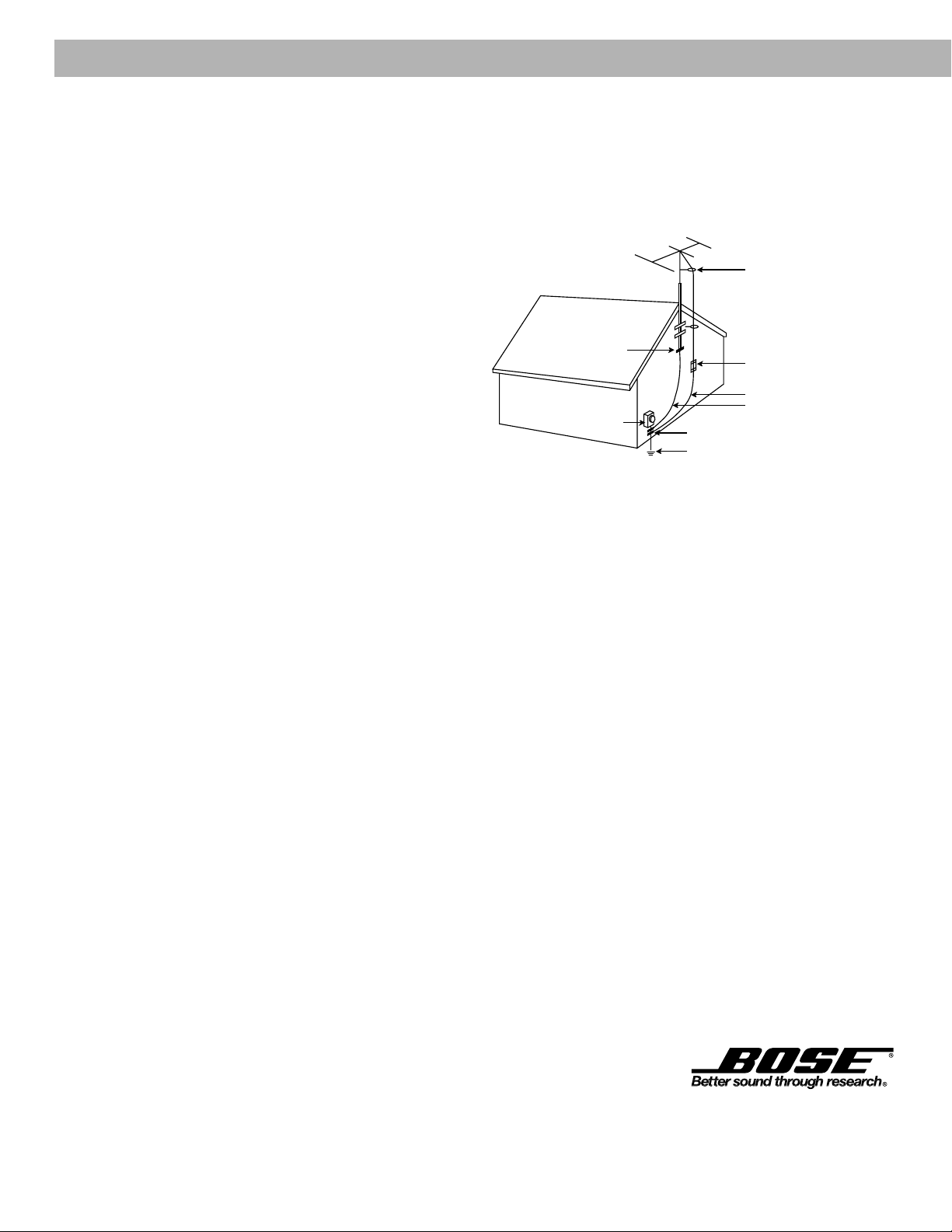
Antenna grounding
Example of antenna grounding as per National Electrical
Code, ANSI/NFP A 70.
Antenna lead in wire
Ground clamp
Electric service
equipment
Ground clamps
Power service grounding
electrode system
(NEC ART 250, Part H)
Antenna discharge unit
(NEC Section 810-20)
Grounding conductors
(NEC Section 810-21)
Note to CATV system installer
This reminder is provided to call the CATV system
installer’s attention to Article 820-40 of the NEC (of USA)
that provides guidelines for proper grounding. In par ticular, it specifies that the cable ground shall be connected
to the grounding system of the building, as close to the
point of cable entry as is practical.
©2001 Bose Corporation,
The Mountain, Framingham, MA
01701-9168 USA
255805 AM Rev .00 JN10494
b December 20, 2001 AM262838_00_V.pdf
Page 5

Where to find…
Contents
Setting Up
Before you begin...........................................................................................................4
Unpacking the carton ...................................................................................................4
Select the location for your speaker system ................................................................5
Speaker locations................................................................................................5
Acoustimass
Before making connections, unplug your system............................................... 6
Selecting the correct voltage .............................................................................. 6
Connect the speakers and the Acoustimass module ...................................................7
Connecting the Acoustimass 20 Jewel Cube® speakers to the
Acoustimass module .................................................................................... 7
Connecting the Acoustimass 5 cube speaker arrays to the
Acoustimass module .................................................................................... 7
Which Lifestyle® system do you own? ..........................................................................8
Connecting the Acoustimass module to multi-room interface systems....................... 9
Connecting the Acoustimass module to the Lifestyle® media center .........................12
Setting Zone 2 Protocol..............................................................................................13
Connecting the Acoustimass module to the Model 20 music center......................... 14
Connecting the Acoustimass module to the Model 5 music center........................... 15
Fine-tuning your system ............................................................................................. 16
Product Information
Troubleshooting ..........................................................................................................17
Accessories.................................................................................................................17
Customer service........................................................................................................17
Technical information..................................................................................................18
Warranty period .......................................................................................................... 18
Cleaning the Acoustimass 5 or 20 powered speaker systems................................... 18
®
module location............................................................................6
AM262838_00_V.pdf December 20, 2001 3
Page 6
Setting Up
Before you begin
Thank you for purchasing the Bose® Acoustimass® 5 or 20 powered speaker system. These
speakers are designed specifically for use with the Bose Lifestyle® music systems to deliver
high-fidelity, room-filling sound to additional rooms in your home.
Because these speakers are different from other systems, we recommend that you take the
time to read this owner’s guide. It contains instructions and information that will help you get
the most enjoyment possible from your new speakers.
Unpacking the carton
Carefully unpack your speakers. Save all packing materials for possible future use. The
original packing materials provide the safest way to transport your speaker system. If any part
of the product appears damaged, do not attempt to use the system. Notify Bose or your
authorized Bose dealer immediately.
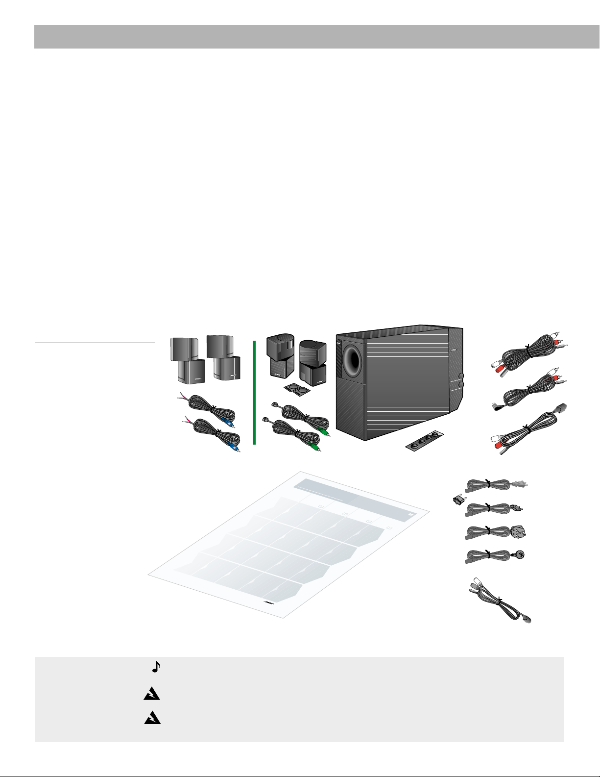
Check to be sure your Acoustimass 5 or 20 powered speaker system contains the parts
identified in Figure 1.
Figure 1
What comes with your
Acoustimass powered speaker
system:
• Owner's guide
• Quick set-up guide
• 2 cube arrays
• 1 Acoustimass module
• Speaker wire
• Rubber feet
• 3-foot VAR adapter cable
• 3-foot FIX adapter cable
for Lifestyle
®
DVD
systems
• 50-foot extension cable
• 30-foot audio input cable
• AC power (mains)
adapter plug (in dual voltage
systems)
• Power cord
Speaker
wire
Quick set-up
Cube speaker
arrays
R
L
guide
Speaker
wire
Acoustimass 5 & 20 Powered
Speaker Systems
1
1
2
2
Acoustimass
module
¤
3
3
4
4
5
5
Rubber feet
Adapter
plug
50-foot extension
cable
30-foot
audio
input
cable
3-foot
VAR
adapter
cable
Power
cords
?
bose.com
?
3-foot FIX
adapter cable
for Lifestyle® DVD
systems
Note:
Find the serial numbers on the bottom panel of the Acoustimass module. Then write
them on your warranty card.
WARNING:
The Acoustimass module weighs 33 pounds (15 kg). Use good lifting practice
to avoid injury.
WARNING:
To avoid danger of suffocation, keep the plastic bags out of the reach of
children.
4 December 20, 2001 AM262838_00_V.pdf
Page 7

Select the location for your speaker system
When you place your speakers according to the guidelines below, a combination of reflected
and direct sound provides a good stereo image virtually everywhere in the room. You may
experiment with the placement and orientation of the cubes and the Acoustimass® module to
produce the sound most pleasing to you.
To adjust your system for the characteristics of your listening room, see “Fine-tuning your
system” on page 16.
Speaker locations
Follow these guidelines to select locations for your Acoustimass 5 or 20 speaker system.
speaker cables allow up to 20 feet (6.1 m) distance from the Acoustimass module.
1. For the most lifelike sound, place the cube arrays 6-12 feet (1.8-3.6 m) apart. They can be
as close as 3 feet (0.9 m) or as far apart as 15 feet (4.6 m).
2. Direct one cube of each array forward. Direct the other cube toward the wall or in a
different direction to create reflected sound. (See the illustration of reflected sound patterns in Figure 2.)
Setting Up
The
Figure 2
Recommended speaker
locations
Left speaker
Right speaker
Acoustimass
module
CAUTION:
Choose a stable and level surface for your speakers. Vibration can cause the
speakers to move, particularly on smooth surfaces like marble, glass, or highly polished
wood. For additional stability, you can add rubber feet to your speakers. You may obtain
rubber feet (part no. 178321) free of charge from Bose®. Contact Bose Customer Service for
more information.
Note:
If you put the speakers in a bookcase unit, be sure to place each one at the front
edge of the shelf. Placing speakers in an enclosed space can change the tonal quality of the
sound. This effect is minimized if the shelves are filled with books.
Note:
The cube speakers are magnetically shielded so you can place them close to a
TV without affecting picture quality.
AM262838_00_V.pdf December 20, 2001 5
Page 8

RIGHT
OUTPUTS
TO
CUBE
SPEAKERS
LEFT
AUDIO
INPUT
OFF
POWER
ON
Setting Up
Select the locations for your speaker system (cont.)
Acoustimass® module location
Follow these guidelines to select a location for the Acoustimass module.
1. Place the module along the same wall as the speakers, if possible.
2. Select a convenient location – under a table, behind a sofa. Do not allow furniture or
drapes to block the ventilation openings of the module.
3. Place the module within reach of the audio input cable, speaker cables, and an AC power
(mains) outlet.
4. Select a position for the Acoustimass module (Figure 3). For proper ventilation, place it on
the long edge, with the connectors facing the floor. An alternate position is on its largest
side, with the bass and treble controls facing up. Do not place the module on either end,
as shown by the last two views in Figure 3.
Figure 3
Acoustimass module positions
Preferred
position
®
T
r
e
b
l
e
B
a
s
s
Alternate position
®
AUDIO
INPUT
RIGHT
OUTPUTS
TO
CUBE
SPEAKERS
LEFT
OFF
POWER
ON
®
5. Once you have selected a position for the module, place the four self-adhesive rubber feet
near the corners of the bottom surface. The rubber feet provide increased stability and
protection from scratches.
6. Aim the port (the round opening) into the room or along the wall to avoid blocking the port
or creating too much bass.
7. For best bass performance, do not place the port at equal distances from any two walls or
from a wall and the ceiling.
Before making connections, unplug your system
It is important that you unplug your Lifestyle® system or other music source before making
any connections.
Selecting the correct voltage
If you purchased a dual voltage product, please be sure that your speakers are set to the
correct voltage for your geographical area. Use the adapter plug provided when appropriate.
Figure 4
Voltage selector switch settings
®®
CAUTION:
Do not cover the ventilation openings of the Acoustimass module. The slots on
the end provide ventilation for the built-in electronic circuitry, and should not be blocked.
Note:
To avoid interference with the TV picture, place the Acoustimass module at least
18 inches (45 cm) from a TV.
6 December 20, 2001 AM262838_00_V.pdf
Page 9

Connect the speakers and the Acoustimass® module
Connecting the Acoustimass 20 Jewel Cube® speakers to the
Acoustimass module
1. Insert the connector of each speaker cable fully into the jack on the rear of each speaker
(Figure 5). Match the ridge of the connector to the notch at the top of the jack.
2. Connect each 20-foot (6.1 m) cable to the corresponding left or right green jack on the
Acoustimass module. Speaker cables have green connectors at one end, with L (left) and
R (right) molded into the connectors.
To extend the length of speaker cable, you will need a 30-foot extension cable. To order this
part, please call Bose® customer service (request PN 186445-1 black; PN 186445-2 white).
Or, splice in 18-gauge (.75 mm2) or thicker cord (connecting + to + and – to –). To purchase
extension wire, see your dealer, electronics store, or call Bose customer service.
Figure 5
Speaker cable connections to
the Jewel Cube speaker array
Setting Up
Figure 6
Speaker cable connections to
the cube speaker array
Connecting the Acoustimass 5 cube speaker arrays to the
Acoustimass module
Each speaker cable contains two wires. The wire marked with a r ed collar is positive (+) and
the ribbed one is negative (–). These wires match the positive (red) and negative (black)
terminals on the back of each speaker. To extend the length of speaker cable, you will need a
30-foot extension cable. To purchase this cable see dealer, electronics store, or call Bose
customer service. To order this part from Bose, please call Bose customer service (request
PN 186445-1 black; PN 186445-2 white). Or, splice in 18-gauge (.75 mm2) or thicker cord
(connecting + to + and – to –).
1. Match the correct cable to the corresponding speaker location.
• Speaker cables have blue connectors at one end, with L and R molded into the
connectors.
• The red collars on the + wire ar e labeled LEFT and RIGHT.
2. Connect the wire end of one speaker cable to the terminals on the rear of the matching
cube speaker array.
a. Press the terminal tab on the back of the cube array to insert the marked wire into the
red terminal and the plain wire into the black terminal. Release the tab to secure the
wire.
b. Repeat this step for each of the cube speaker arrays (see Figure 6).
3. Connect each cable to the corresponding left or right blue jack on the Acoustimass
module.
CAUTION:
wires create short circuits that affect proper operation of your system.
AM262838_00_V.pdf December 20, 2001 7
Make sure no strands of wire from any terminal touch any other terminal. Bridged
Page 10

LR
TAPE IN
LR
TAPE OUT
Setting Up
Which Lifestyle® system center do you own?
Identifying multi-room interface systems
Figure 7
Front and rear of the multi-room
interface and Personal
center
®
music
Figure 8
Front and rear of the Lifestyle
media center
®
Figure 9
Front and rear of the Model 20
music center
AUDIO INPUT AUDIO OUTPUT
RECORD
AUX VIDEO 1 VIDEO 2 TAPE IN OUT
ANTENNA
LLLLL
FM AM
LOCATE
MUSIC
CENTER
RRRRR
BOSE CD
ROOM A
(PRIMARY)
ROOM B
POWER
!
SEE USER’S
GUIDE
12V AC
1.6A
SERIAL
DATA
ROOM DROOM C
The multi-room interface allows you to connect up to four rooms or listening areas with
additional speakers. These systems are operated using a Personal music center. To connect
additional speakers to a multi-room interface, see “Connecting the Acoustimass
®
module to multi-room interface systems” on page 9.
Identifying systems with the Lifestyle® media center
SENSOR
IR
EMITTER
SERIAL
DATA
1
2
SPEAKER
ZONES
AM
ANTENNA
INPUT OUTPUT
FM
75
OPTICALOPTICAL
AUDIO OUTPUTS
LLLLL
R
RRRR
DIGITAL
Ω
DIGITAL DIGITAL DIGITAL DIGITAL
AUDIO INPUTS
VIDEO INPUTS
COMPOSITE S-VIDEO
COMPOSITE S-VIDEO
VIDEO OUTPUTS
RECORD TAPE AUX VCR TV
33V
DC
POWER
1.1A
TV
The Lifestyle® media center includes a single-disc DVD/CD player and two mini-DIN speaker
output jacks labeled ZONE 1 and ZONE 2 on the rear panel. To connect additional speak-
ers to a Lifestyle® media center, see “Connecting the Acoustimass module to the
Lifestyle® media center” on page 12.
Identifying systems with the Model 20 music center
®
Figure 10
Front and rear of the Model 5
music center
The Model 20 music center includes a six-disc CD player and two mini-DIN speaker output
jacks, labeled ZONE 1 and ZONE 2, on the rear panel. To connect additional speakers to a
Model 20 music center, see “Connecting the Acoustimass module to the Model 20
music center” on page 14.
Identifying systems with the Model 5 music center
®
FM 75
OP
® MODEL 5 MUSIC CENTER
COVERED BY U.S. PATENT D339,606
:
D
E
R
U
T
C
A
F
U
N
A
M
B
E
O
C
S
O
R
O
R
P
A
T
O
I
LIFESTYLE
F
N
,
R
M
A
N
I
0
G
H
M, MA
A
1
7
0
1
-
L
FIXED
R
B
PLAY
REC
A
TAPE
9
1
6
8
D
MA
SPEAKERS
E
N
I
A
U
.
S
.
OUTPUT
The Lifestyle® 5 music center includes a single-disc CD player and three RCA pairs of speaker
output jacks, labeled A, B, and FIXED, on the rear panel. To connect additional speakers to
a Model 5 music center, see “Connecting the Acoustimass module to the Model 5
music center” on page 15.
Ω
LO
AM
1
L
R
VIDEO
AUX
SOUND
INPUT
POWER
12VAC IN
SYSTEM
1.0A
CONTROL
2
ANTENNA
SEE INSTRUCTION MANUAL
8 December 20, 2001 AM262838_00_V.pdf
Page 11

Setting Up
Connecting the Acoustimass® module to multi-room interface systems
Figure 11
Connecting the speakers to
your multi-room interface
Note:
To extend the length of the cables, use the supplied 50-foot extension cable (shown
in the dotted line above). This cable connects between the 30-foot audio input cable and the
3-foot VAR adapter cable.
To connect the Acoustimass 5 or 20 powered speakers to your system, follow these steps:
1. Using the supplied 30-foot audio input cable, insert the round DIN connector into the
Acoustimass module, and the RCA plugs into the supplied 3-foot VAR adapter cable
labeled VAR on the single-connector end.
2. Attach the single-connector end of the 3-foot VAR adapter cable to one of the unused
ROOM output jacks (B, C, D) on the rear of the multi-room interface (Figure 11).
AUDIO
INPUT
RIGHT
OUTPUTS
TO
CUBE
SPEAKERS
LEFT
OFF
POWER
ON
LOCATE
MUSIC
CENTER
ANTENNA
LLLLL
FM AM
RRRRR
BOSE CD
AUDIO INPUT AUDIO OUTPUT
AUX VIDEO 1 VIDEO 2 TAPE IN OUT
RECORD
ROOM A
(PRIMARY)
ROOM B
POWER
!
SEE USER’S
GUIDE
12V AC
1.6A
SERIAL
DATA
ROOM DROOM C
VAR
Connecting power to your system
CAUTION
to the correct voltage. To do this, refer to “Selecting the correct voltage” on page 6.
Follow these steps to connect power to your Acoustimass powered speaker system:
1. Plug the power cord from the Acoustimass module into an AC power (mains) outlet.
2. Insert the power cord of the Lifestyle® system into an AC power (mains) outlet.
3. Turn the Acoustimass module power switch to the On position.
: If you purchased a dual-voltage system, it is important that you set the speakers
Operating in more than one room
Your Lifestyle® system Personal® music center can control up to four sets of Bose® powered
speakers, allowing your family to enjoy four different audio sour ces (CD, radio, TV, etc.) in up
to four rooms. These rooms are referred to as room A, B, C, and D, with room A being the
primary room (the one used for a one-room system). If two or mor e rooms are connected to
your system, the Personal music center displays ROOM and HOUSE buttons, and room
indicators (A, B, C, and/or D). Figure 12 shows a sample display for a two-room system.
Note:
Do
not
plug the AC power pack into a power outlet until all component connections
are complete.
AM262838_00_V.pdf December 20, 2001 9
Page 12

Setting Up
Figure 12
Example display for a two-room
system
The ROOM button lets you control a single room, or two or more rooms that share a source
The HOUSE button lets you control all connected rooms as one
The room indicators tell you what was selected by the ROOM or
HOUSE button
A boxed letter indicated the presently-selected room or rooms.
B An unboxed letter indicates a room listening to a shared source.
An empty box appears for each connected room when you press the HOUSE button.
Turning on different sources in more than one room
Let’s say you have a two-room system (rooms A and B) and the entire system is off. To turn
on a different source in each room:
1. Wake up the touchscreen.
2. Press the ROOM button until the room indicator is displayed. Press a source button,
such as VIDEO 1, to turn on the system and listen to your DVD player in room A.
Adjust the volume to the desired level.
3. Press the ROOM button again. The room indicator is displayed. Pr ess a different
source button, such as CD, to listen to a CD in room B. Again, adjust the volume to the
desired level.
4. Press the ROOM button again and notice that the room indicator is displayed. You are
controlling room A once again and the display indicates that the VIDEO 1 source is on.
Setting up a shared source
Now, let’s say the system is already on and you want to play the FM radio in rooms A and B:
1. Wake up the touchscreen.
2. Press the ROOM button until the room indicator is displayed. Press the FM source
button and adjust the volume to the desired level for room A.
3. Press the ROOM button again to select room . Press the FM source button and adjust
the volume to the desired level for room B. Now, the indicators A are displayed.
4. Press the ROOM button again. The indicators appear on the touchscreen indicating that you can control these two rooms together. Any button command given now
(SOURCE, VOLUME, MUTE, ON/OFF, SLEEP) is applied to both rooms.
10 December 20, 2001 AM262838_00_V.pdf
Page 13

Setting Up
Using the HOUSE button
Using the HOUSE button, you can link all the rooms together and control them as one.
When you press the HOUSE button, an empty box indicator is displayed for each connected
room. Any button pressed after that (any source button, VOLUME, MUTE, or SLEEP) affects
every room. When you are done listening you can press OFF to turn off the entire system.
Note: If you do not press any other buttons after pressing HOUSE, pressing HOUSE again
cancels HOUSE mode.
Using more than one Personal
If you have a multi-room system, you can add Personal music centers for some or all of the
connected rooms. Each multi-room interface can be controlled by a maximum of four
Personal music centers. Each Personal music center can control up to four rooms.
®
music center
AM262838_00_V.pdf December 20, 2001 11
Page 14

O
P
T
IC
A
L
O
P
T
IC
A
L
D
IG
IT
A
L
RR
IN
P
U
T
O
U
T
P
U
T
A
U
D
IO
O
U
T
P
U
T
S
A
N
T
E
N
N
A
S
P
E
A
K
E
R
Z
O
N
E
S
2
1
F
M
A
M
7
5
Setting Up
Connecting the Acoustimass® module to the Lifestyle® media center
Figure 13
Connecting the speakers to
your Lifestyle
®
media center
V
T
R
C
V
X
S
U
T
A
U
P
N
I
O
E
E
D
P
I
V
O
TA
E
D
I
-V
S
D
R
O
E
C
IT
E
S
R
AUDIO
INPUT
RIGHT
OUTPUTS
TO
CUBE
SPEAKERS
LEFT
OFF
POWER
ON
R
E
W
O
P
C
D
V
3
3
A
1
.
1
V
T
M
A
R
O
S
N
E
F
S
E
T
N
A
L
IR
A
IC
T
P
O
R
E
T
IT
M
E
1
L
IA
R
E
S
T
U
TA
P
A
D
IN
2
R
E
K
A
E
P
S
S
E
N
O
Z
LLLLL
75
M
A
N
N
RRRR
R
L
A
IC
T
P
O
L
A
T
I
IG
D
T
U
P
T
S
T
U
U
O
P
T
U
O
IO
D
U
A
O
P
M
O
C
O
E
D
I
-V
S
E
IT
S
S
O
L
T
P
A
U
M
T
I
P
O
T
G
I
C
U
D
O
O
E
L
ID
A
T
V
I
G
I
D
L
A
T
I
G
I
D
L
S
A
T
T
I
U
P
IG
D
IN
O
I
D
U
A
FIX
Figure 14
Setting up a Zone 2 remote
control
Note:
To extend the length of the cables, use the supplied 50-foot extension cable (shown in
the dotted line above). This cable connects between the 30-foot audio input cable and the 3foot FIX adapter cable.
To connect the Acoustimass 5 or 20 powered speakers to your system (Figure 13), follow
these steps:
1. Using the supplied 30-foot audio input cable, insert the DIN connector into the
Acoustimass module, and the RCA plugs into the supplied 3-foot adapter cable labeled
FIX on the single-connector end.
2. Attach the end of the 3-foot FIX adapter cable to the ZONE 2 output jack on the rear of the
Lifestyle® media center.
Setting up the remote control
You need to set up a second remote control to operate the ZONE 2 output.
1. Remove the remote control battery cover and locate the miniatur e switches (Figure 14).
2. Make sure that the house code settings (switches 1, 2, 3, and 4) match those on your first
remote.
3. Make sure switches 5, 7, and 8 are up, and 6 and 9 are down.
Note:
Refer to your Lifestyle® system owner’s guide for more information on operating your
system in more than one room.
ON
12 December 20, 2001 AM262838_00_V.pdf
Page 15

Setting Up
Setting Zone 2 Protocol
For the Acoustimass® 5 or 20 powered speaker system to work properly with a Lifestyle® media center,
you will need to check the Zone 2 Protocol to ensure that it is set to Normal mode (Figur e 14 a).
1. While your Lifestyle
the on-screen display.
2. Scroll down with the down-arrow button and select System Setup using the Enter button.
3. You will now see a menu entitled System Setup (1 of 3). Scroll down to “more...”.
Continue to scroll down through (2 of 3) to (3 of 3). The last item on System Setup (3 of 3) is Zone 2
Protocol.
4. If necessary, use the right-arrow button to set the protocol from Legacy to Normal.
5. If you changed the Zone 2 Protocol, shut off the system and turn it on again; this ensures that the
Zone 2 Protocol is reset to Normal mode.
®
system is on, press the Settings button on your remote contr ol. This will open
Figure 14 a
Setting Zone 2 Protocol
Mute
On
Mute
Off
All
SOURCE / INPUT
CD/DVD
Changer
FM/AM
TV
VCR
AUX
MENU / NAVIGATION
Settings
Tune
Disc
Seek
Channel
Chapter
Preset
Track
1
4
7
Stop
Shuffle
Settings
Enter
Volume
3
2
6
5
9
8
0
PLAYBACK
Pause
Play
Repeat
Settings ( )
System Setup
Enter
System Setup (3 of 3)
Zone 2 Protocol: Normal
Connecting power to your system
CAUTION
correct voltage. To do this, refer to “Selecting the correct voltage” on page 6.
Follow these steps to connect power to your Acoustimass powered speaker system:
1. Plug the power cord from the Acoustimass module into an AC power (mains) outlet.
2. Insert the power cords of the Lifestyle® system into an AC power (mains) outlet.
3. Turn the Acoustimass module power switch to the On position.
: If you purchased a dual-voltage system, it is important that you set the speakers to the
AM262838_00_V.pdf December 20, 2001 13
Page 16

Setting Up
Connecting the Acoustimass® module to the Model 20 music center
Figure 15
Connecting the speakers to
your Model 20 music center
Note:
To extend the length of the cables, use the supplied 50-foot extension cable (shown
in the dotted line above). This cable connects between the 30-foot audio input cable and the
3-foot VAR adapter cable (Figure 15).
To connect the Acoustimass 5 or 20 powered speakers to your system (Figure 15), follow
these steps:
1. Using the supplied 30-foot audio input cable, insert the round DIN connector into the
Acoustimass module, and the RCA plugs into the supplied 3-foot adapter cable labeled
VAR on the single-connector end.
2. Attach the end of the 3-foot VAR adapter cable to the ZONE 2 output jack on the rear of
the Model 20 music center.
VAR
Figure 16
Setting up the remote control
Setting up the remote control
You need to set up a second remote control to operate the ZONE 2 outputs.
1. Remove the remote control battery cover and locate the miniatur e switches (Figure 16).
2. Make sure that the house code settings (switches 1, 2, 3, and 4) match those on your first
remote.
3. Set switch 8 up for ZONE 2.
Connecting power to your system
CAUTION
to the correct voltage. To do this, refer to “Selecting the correct voltage” on page 6.
Follow these steps to connect power to your Acoustimass powered speaker system:
1. Plug the power cord from the Acoustimass module into an AC power (mains) outlet.
2. Insert the power cords of the Lifestyle® system into an AC power (mains) outlet.
3. Turn the Acoustimass module power switch to the On position.
: If you purchased a dual-voltage system, it is important that you set the speakers
14 December 20, 2001 AM262838_00_V.pdf
Page 17

Setting Up
L
I
F
E
S
T
Y
L
E
®
M
O
D
EL
5 M
U
S
IC
C
E
N
T
E
R
L
R
A
B
S
P
E
A
K
E
R
S
O
U
T
P
U
T
T
A
P
E
R
E
C
P
L
A
Y
F
IX
E
D
O
U
T
P
U
T
L
R
A
U
X
V
ID
E
O
S
O
U
N
D
A
N
T
E
N
N
A
1
2
S
Y
S
T
E
M
C
O
N
T
R
O
L
S
E
E
I
N
S
T
R
U
C
T
I
O
N
M
A
N
U
P
O
W
E
1
2
V
A
C
1
.
0
A
A
M
L
O
O
P
F
M
7
5
Ω
7
0
1
9
1
6
8
M
A
D
E
I
N
U
.
S
.
A
Connecting the Acoustimass® module to the Model 5 music center
Figure 17
Connecting the speakers to your
Model 5 music center
Note:
To extend the length of the cables, use the supplied 50-foot extension cable (shown
as the dotted line above). This cable connects between the 30-foot audio input cable and
the music center.
To connect the Acoustimass 5 or 20 powered speakers to your system, refer to Figure 17 and
follow these steps:
1. Using the supplied 30-foot audio input cable, insert the round DIN connector into the
Acoustimass module.
2. At the other end of that cable, connect the RCA plugs to SPEAKERS B and the 3.5 stereo
mini plug to SYSTEM CONTROL 2 on the music center.
AUDIO
INPUT
RIGHT
OUTPUTS
TO
CUBE
SPEAKERS
LEFT
OFF
POWER
ON
L
I
F
E
S
T
Y
L
E
®
M
O
D
E
L
5
M
U
S
I
C
C
E
N
T
E
R
L
C
O
V
E
R
E
D
B
Y
U
.
S
.
P
A
T
E
N
T
D
3
3
9
,
6
0
6
M
A
N
U
F
A
C
T
U
R
E
D
:
R
B
O
S
E
C
O
R
P
O
R
A
T
I
O
N
,
F
R
A
M
I
N
G
H
A
M
,
M
A
0
1
7
0
1
-
9
1
6
8
M
A
D
E
IN
U
.
S
.
A
FM
75
Ω
AM
LOOP
L
F
I
X
E
D
A
B
S
P
E
A
K
E
R
S
R
O
U
T
P
U
T
1
P
OW
ER
12V
A
C
I
S
Y
N
S
T
E
M
1.0A
R
C
O
N
T
R
O
E
C
T
A
P
E
L
P
L
A
Y
2
V
I
D
E
A
O
U
X
S
O
U
N
D
O
U
T
P
U
T
A
N
T
E
N
N
A
S
E
E
I
N
S
T
R
U
C
T
I
O
N
M
A
N
U
A
L
Figure 18
Setting up the remote control
Setting up the remote control
You need to set up a second remote control to operate the SPEAKERS B outputs.
1. Remove the remote control battery cover and locate the miniatur e switches (Figure 18).
2. Make sure that the house code settings (switches 1, 2, 3, 4) match those on your first
remote.
3. Set switches 5 down and 6 up for SPEAKERS B.
40
ON
234l
K
5678
Connecting power to your system
CAUTION
to the correct voltage. To do this, refer to “Selecting the correct voltage” on page 6.
Follow these steps to connect power to your Acoustimass powered speaker system:
1. Plug the power cord from the Acoustimass module into an AC power (mains) outlet.
2. Insert the power cord of the Lifestyle® system into an AC power (mains) outlet.
3. Turn the Acoustimass module power switch to the On position.
: If you purchased a dual-voltage system, it is important that you set the speakers
AM262838_00_V.pdf December 20, 2001 15
Page 18

Setting Up
Setting Up
Fine-tuning your system
In most situations, you only need to follow the speaker placement guidelines for your system
to provide excellent sound quality.
Figure 19
English
Bass and treble controls
®
T
r
e
b
l
e
B
a
s
s
You do not need to adjust tone settings for changes in volume, since Bose
processing technology provides a natural tonal balance over the full range of volume settings.
If desired, you can further fine-tune your system as described below.
Adjusting speaker controls
The TREBLE and BASS controls are located on the Acoustimass® 5 and 20 music systems’
Acoustimass module (Figure 19). They allow you to adjust the treble (high frequencies) and
bass (low frequencies). In the normal setting, the dots on each control are in the 12-o’clock
position. Turn the controls clockwise to increase and counterclockwise to decrease the
amount of treble or bass.
Compensating for room acoustics
The acoustics (sound qualities) of your room can affect the overall sound quality of any
speaker system. In general, you can reduce many problems with acoustics by the careful use
of the TREBLE and BASS controls.
Too much or too little treble
Rooms with too few sound-absorbing furnishings, especially those with bare floors and walls,
may sound overly shrill or “bright.” Turning down the treble control (toward –) decreases
treble sound.
Rooms with a lot of sound-absorbing furnishings, such as upholstered furniture, wall-to-wall
carpet, or heavy drapes, may reduce the treble sound of your system. Moving speakers
farther away from soft furnishings increases treble. You can increase treble sound by slightly
turning up the treble control (toward +).
®
patented signal
Too much or too little bass
You can decrease bass sound by turning down the bass control (toward –). To increase bass,
turn up the bass control (toward +).
Acoustimass module placement affects the amount of bass you hear. Placing the module
closer to the corner of the room will increase bass. Moving the module away from the corner
will decrease bass.
16 December 20, 2001 AM262838_00_V.pdf
Page 19

Product Information
Product Information
Troubleshooting
Problem What to do
System does not function at all • Make sure the power connector is plugged securely into the music center, the power cord is
plugged securely into the Acoustimass® module, the power pack and power cord are
plugged into operating AC wall outlets, and the module power switch is on.
• Be sure to select a source (CD, AM/FM, etc.).
• Unplug the music center power pack for a minute, then reconnect it. This allows the unit to
reset itself after a power surge or power interruption.
No sound • Turn the music center off for ten seconds, then on again, to re-establish communication
between the music center and the speakers.
• Check the connections for any external components. Make sure to select the
correct source for the desir ed input.
• Check the speaker connections.
• Be sure the CD is placed correctly, label-side up, in the music center, and the cover is
closed.
• Increase the volume.
• Check to see if MUTE is lit in the display. Press MUTE on the remote to unmute the sound.
• Disconnect any headphones.
• Connect the FM and AM antennas.
English
Volume at maximum level • For Lifestyle® DVD systems, check Zone 2 Protocol in the System Settings menu. This
and cannot be adjusted
Hear only static
must be set to Normal.
• For Lifestyle® DVD systems, check that the FIX adapter cable is plugged into the Zone 2
output. If it is not, replace VAR 3-foot adapter cable with FIX 3-foot adapter cable.
Accessories
The following accessories are available to enhance the flexibility of your Bose® powered
speaker system. Contact your Bose dealer or call Bose directly. Refer to the address list
enclosed in the product packaging for correct phone numbers.
UB-20: High-quality cast zinc bracket for wall or ceiling mounting.
UFS-20: Slender metal floor stands, 37"H (93.98 cm), elegantly display cube speakers
while hiding the speaker wires.
UTS-20: High-quality cast aluminum stands, 7"H (17.78 cm), for placement
on a flat surface, like a bookshelf or table.
Customer Service
For assistance, contact Bose customer service. Refer to the address list enclosed in the
product packaging for correct phone numbers.
Note:
Your Acoustimass powered speaker system should be mounted only in the manner
recommended by Bose. Consult the instructions supplied with the mounting accessories.
AM262838_00_V.pdf December 20, 2001 17
Page 20

Product Information
Technical Information
English
Power rating
USA/Canada: 120VAC, 50/60 Hz, 350W
Dual Voltage: 115/230VAC, 50/60 Hz, 350W
Dimensions
Acoustimass® 5 powered speaker system:
Cube speakers: 3.1"W x 4"D x 6.2"H (7.8 x 10.2 x 15.8 cm)
Acoustimass module: 23.3"W x 7.5"D x 14"H (59 x 19 x 35.5 cm)
Acoustimass 20 powered speaker system:
Jewel Cube® speakers: 2.2"W x 3.2"D x 4.4"H (5.6 x 8.2 x 11.2 cm)
Acoustimass module: 23.3"W x 7.5"D x 14"H (59 x 19 x 35.5 cm)
Weight
Acoustimass 5 powered speaker system:
Cube speakers: 2.4 lb (1.11 kg); Acoustimass module: 33 lb (15 kg)
Acoustimass 20 powered speaker system:
Jewel Cube® speakers: 1 lb (.5 kg); Acoustimass module: 33 lb (15 kg)
Finish
Cube speakers: Polymer, painted
Acoustimass module: Vinyl veneer
Warranty period
The Acoustimass 5 and 20 powered speaker systems are cover ed by the Bose® limited oneyear transferable warranty. Details of the warranty are provided on the warranty card that
came with your system. Please fill out the information section on the card and mail it to Bose
Corporation.
Cleaning the Acoustimass 5 or 20 powered speaker system
Clean the surface of your speakers with a soft, damp cloth. Do not use any sprays near the
system. Do not use any solvents, chemicals, or cleaning solutions containing alcohol, ammonia, or abrasives. Do not allow liquids to spill into any openings.
The speaker grille panels require no special care, though you may vacuum them carefully with
a soft-bristled attachment, if necessary.
18 December 20, 2001 AM262838_00_V.pdf
Page 21

Bose® Corporation
AM262838_00_V.pdf December 20, 2001 19
Page 22

©2002 Bose Corporation,
The Mountain,
Framingham, MA 01701-9168 USA
262838 AM Rev. 00 JN20604
 Loading...