

Page 1

The Bose® Acoustimass® 5 and 20 Powered Speaker System
Owner’ s Guide
Page 2
Safety/Maintenance Information
English
CAUTION: TO REDUCE THE RISK OF ELECTRIC SHOCK,
WARNING:
To r educe the risk of fire or electric shock, do not expose the system to rain or
moisture.
CAUTION AVIS
RISK OF ELECTRICAL SHOCK RISQUE DE CHOC ÉLECTRIQUE
DO NOT OPEN NE PAS OUVRIR
DO NOT REMOVE COVER (OR BACK).
NO USER-SERVICEABLE PARTS INSIDE.
REFER SERVICING TO QUALIFIED PERSONNEL.
These CAUTION marks are located on the bottom of your Lifestyle® Acoustimass® module:
The lightning flash with arrowhead symbol, within an equilateral triangle, is intended to alert
the user to the presence of uninsulated dangerous voltage within the system enclosure that
may be of sufficient magnitude to constitute a risk of electric shock.
The exclamation point within an equilateral triangle, as marked on the system, is intended to
alert the user to the presence of important operating and maintenance instructions in this
owner’s guide.
CAUTION:
To prevent electric shock, match wide blade of plug to wide slot, insert fully.
AFIN DE PRÉVENIR UN CHOC ÉLECTRIQUE NE PAS ENLEVER
LE COUVERCLE ARRIÈRE. IL NE SE TROUVE À L’INTÉRIEUR
AUCUNE PIÈCE POUVANT ÊTRE RÉPARÉE PAR
L’USAGER. S’ADRESSER À UN RÉPARATEUR COMPÉTENT.
Additional safety information
See the additional instructions on the Important Safety Information page enclosed with this
owner’s guide.
Please read this owner’s guide
Please take the time to follow this owner’s guide carefully . It will help you set up and operate
your Acoustimass 5 or 20 powered speaker system properly. Save your owner’s guide for
future reference.
Class B emissions limits
This Class B digital apparatus meets all requirements of the Canadian Interference-Causing
Equipment Regulations.
CAUTION:
If liquids get into the product, turn the system off and allow it to air dry. Then turn
it on again. If you notice any problems with its functioning, unplug it and contact Bose
customer service.
2
Page 3

Contents
Where to find…
Setting Up
Before you begin...........................................................................................................4
Unpacking the carton ...................................................................................................4
Select the location for your speaker system ................................................................ 5
Speaker locations................................................................................................5
Acoustimass
Before making connections, unplug your system............................................... 6
Selecting the correct voltage ..............................................................................6
Connect the speakers and the Acoustimass module ...................................................7
Connecting the Acoustimass 20 Jewel Cube® speakers to the
Acoustimass module ....................................................................................7
Connecting the Acoustimass 5 cube speaker arrays to the
Acoustimass module ....................................................................................7
Which Lifestyle® music center do you own?................................................................. 8
Connecting the Acoustimass module to multi-room interface systems....................... 9
Connecting the Acoustimass module to the model 20 music center......................... 12
Connecting the Acoustimass module to the model 5 music center........................... 13
Fine-tuning your system .............................................................................................14
®
module location............................................................................6
Product Information
Troubleshooting ..........................................................................................................15
Accessories.................................................................................................................15
Customer service........................................................................................................15
Technical information..................................................................................................16
Warranty period ..........................................................................................................16
Cleaning the Acoustimass 5 or 20 powered speaker systems................................... 16
Bose® Corporation....................................................................... inside back cover
English
3
Page 4
Setting Up
Before you begin
English
Unpacking the carton
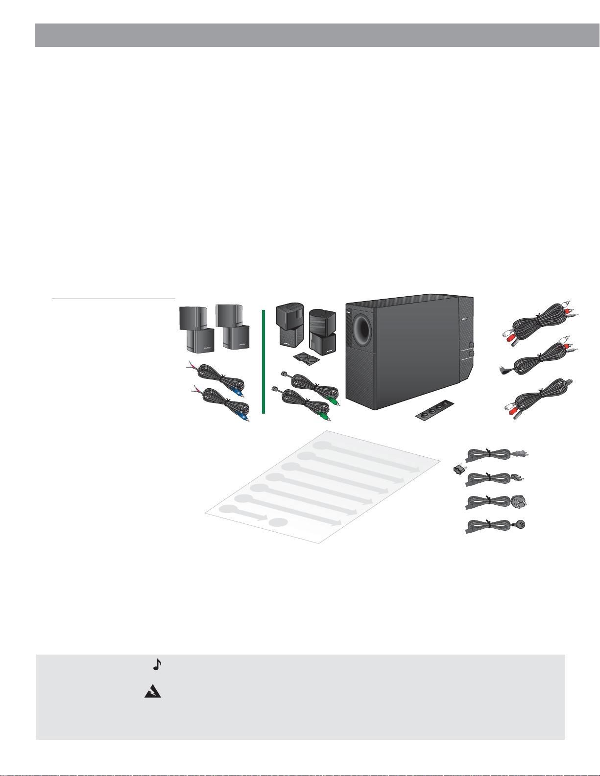
Figure 1
What comes with your Acoustimass powered speaker system:
•2 cube arrays
•1 Acoustimass module
• Speaker wire
• Rubber feet
• 3-foot adapter cable
• 50-foot extension cable
• 30-foot audio input cable
• AC power (mains)
• Power cord
• One owner's guide
• One quick set-up guide
adapter plug (in dual voltage
systems)
Thank you for purchasing the Bose® Acoustimass® 5 or 20 powered speaker system. These
speakers are designed specifically for use with the Bose Lifestyle® music systems to deliver
high-fidelity, room-filling sound to additional rooms in your home.
Because these speakers are different from other systems, we recommend that you take the
time to read this owner’s guide. It contains instructions and information that will help you get
the most enjoyment possible from your new speakers.
Carefully unpack your speakers. Save all packing materials for possible future use. The
original packing materials provide the safest way to transport your speaker system. If any part
of the product appears damaged, do not attempt to use the system. Notify Bose or your
authorized Bose dealer immediately.
Check to be sure your Acoustimass 5 or 20 powered speaker system contains the parts
identified in Figure 1.
Acoustimass
module
Rubber feet
Adapter
plug
50-foot extension
cable
30-foot audio
input cable
3-foot
adapter
cable
Power
cords
Speaker
wire
Quick set-up
Cube speaker
arrays
R
L
guide
Speaker
wire
Note:
Find the serial numbers on the bottom panel of the Acoustimass module. Then write
them on your warranty card.
WARNING:
The Acoustimass module weighs 33 pounds (15 kg). Use good lifting practice
to avoid injury.
WARNING:
To avoid danger of suffocation, keep the plastic bags out of the reach of
children.
4
Page 5
Setting Up
Select the location for your speaker system
When you place your speakers according to the guidelines below, a combination of reflected
and direct sound provides a good stereo image virtually everywhere in the room. You may
experiment with the placement and orientation of the cubes and the Acoustimass® module to
produce the sound most pleasing to you.
To adjust your system for the characteristics of your listening room, see “Fine-tuning your
system” on page 14.
Speaker locations
Follow these guidelines to select locations for your Acoustimass 5 or 20 speaker system.
speaker cables allow up to 20 feet (6.1 m) distance from the Acoustimass module.
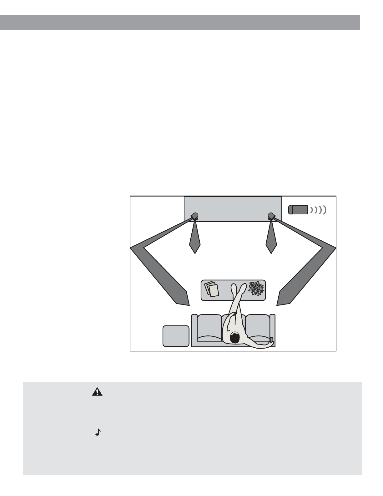
1. For the most lifelike sound, place the cube arrays 6-12 feet (1.8-3.6 m) apart. They can be
as close as 3 feet (0.9 m) or as far apart as 15 feet (4.6 m).
2. Direct one cube of each array forward. Direct the other cube toward the wall or in a
different direction to create reflected sound. (See the illustration of reflected sound patterns in Figure 2.)
Figure 2
Recommended speaker
locations
Left speaker
Right speaker
English
The
Acoustimass
module
CAUTION:
Choose a stable and level surface for your speakers. Vibration can cause the
speakers to move, particularly on smooth surfaces like marble, glass, or highly polished
wood. For additional stability, you can add rubber feet to your speakers. You may obtain
rubber feet (part no. 178321) free of charge from Bose®. Contact Bose Customer Service for
more information.
Note:
If you put the speakers in a bookcase unit, be sure to place each one at the front
edge of the shelf. Placing speakers in an enclosed space can change the tonal quality of the
sound. This effect is minimized if the shelves are filled with books.
Note:
The cube speakers are magnetically shielded so you can place them close to a
TV without affecting picture quality.
5
Page 6
Setting Up
Select the locations for your speaker system (cont.)
Acoustimass® module location
Follow these guidelines to select a location for the Acoustimass module.
English
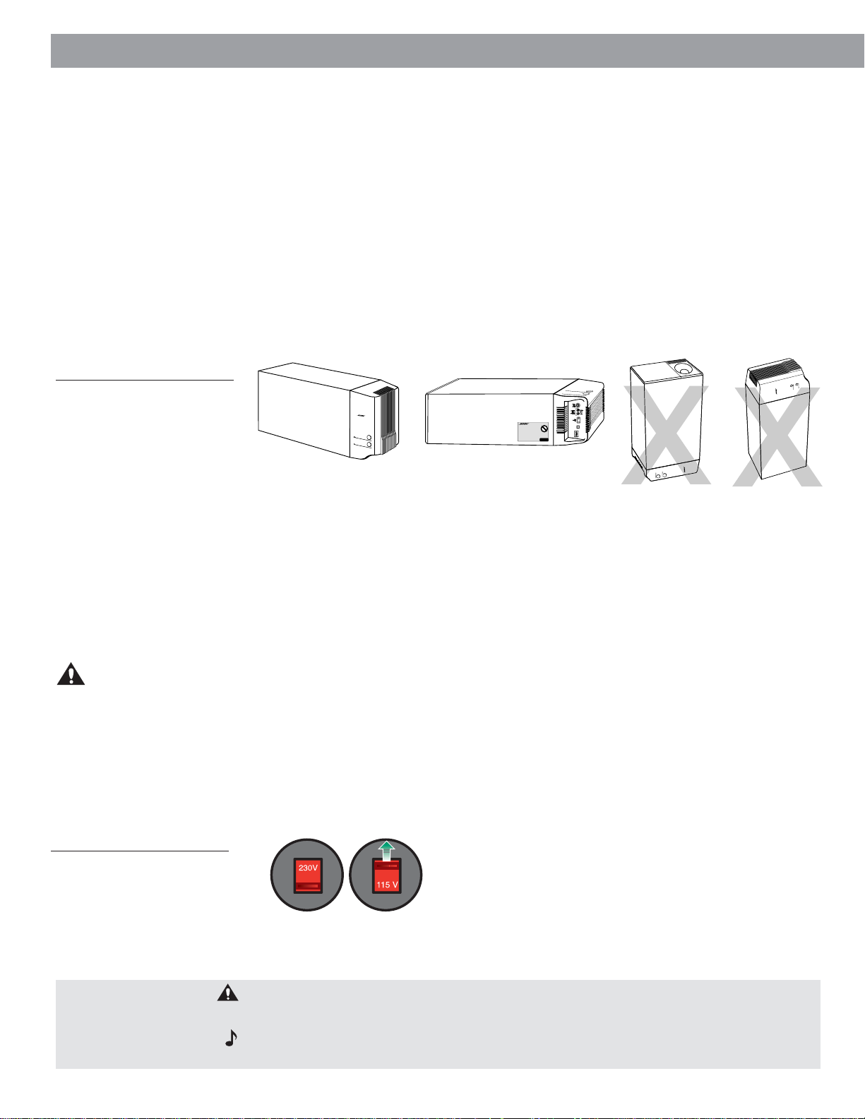
Figure 3
Acoustimass module positions
1. Place the module along the same wall as the speakers, if possible.
2. Select a convenient location – under a table, behind a sofa. Do not allow furniture or
drapes to block the ventilation openings of the module.
3. Place the module within reach of the audio input cable, speaker cables, and an AC power
(mains) outlet.
4. Select a position for the Acoustimass module (Figure 3). For proper ventilation, place it on
the long edge, with the connectors facing the floor. An alternate position is on its largest
side, with the bass and treble controls facing up. Do not place the module on either end,
as shown by the last two views in Figure 3.
Preferred
position
Alternate position
5. Once you have selected a position for the module, place the four self-adhesive rubber feet
near the corners of the bottom surface. The rubber feet provide increased stability and
protection from scratches.
6. Aim the port (the round opening) into the room or along the wall to avoid blocking the port
or creating too much bass.
7. For best bass performance, do not place the port at equal distances from any two walls or
from a wall and the ceiling.
Before making connections, unplug your system
It is important that you unplug your Lifestyle® system or other music source before making
any connections.
Selecting the correct voltage
If you purchased a dual voltage product, please be sure that your speakers are set to the
correct voltage for your geographical area. Use the adapter plug provided when appropriate.
Figure 4
Voltage selector switch settings
CAUTION:
Do not cover the ventilation openings of the Acoustimass module. The slots on
the end provide ventilation for the built-in electronic circuitry, and should not be blocked.
Note:
To avoid interference with the TV picture, place the Acoustimass module at least
18 inches (45 cm) from a TV.
6
Page 7

Setting Up
Connect the speakers and the Acoustimass® module
Connecting the Acoustimass 20 Jewel Cube® speakers to the
Acoustimass module
1. Insert the connector of each speaker cable fully into the jack on the rear of each speaker
(Figure 5). Match the ridge of the connector to the notch at the top of the jack.
2. Connect each 20-foot (6.1 m) cable to the corresponding left or right green jack on the
Acoustimass module. Speaker cables have green connectors at one end, with L (left) and
R (right) molded into the connectors.
To extend the length of speaker cable, you will need a Bose® 30-foot extension cable. To
order this part, please call Bose customer service (request PN 186445-1 black; PN 186445-2
white). Or, splice in 18-gauge (.75 mm2) or thicker cord (connecting + to + and – to –). To
purchase extension wire, see your dealer, electronics store, or call Bose customer service.
Figure 5
Speaker cable connections to
the Jewel Cube speaker array
Connecting the Acoustimass 5 cube speaker arrays to the
Acoustimass module
Each speaker cable contains two wires. The wire marked with a r ed collar is positive (+) and
the ribbed one is negative (–). These wires match the positive (red) and negative (black)
terminals on the back of each speaker. To extend the length of speaker cable, you will need a
Bose 30-foot extension cable. To order this part, please call Bose customer service (request
PN 186445-1 black; PN 186445-2 white). Or, splice in 18-gauge (.75 mm2) or thicker cord
(connecting + to + and – to –). To purchase cables, see your dealer, electronics store, or call
Bose customer service.
1. Match the correct cable to the corresponding speaker location.
• Speaker cables have blue connectors at one end, with L and R molded into the
connectors.
• The red collars on the + wire are labeled LEFT and RIGHT.
2. Connect the wire end of one speaker cable to the terminals on the rear of the matching
cube speaker array.
a. Press the terminal tab on the back of the cube array to insert the marked wire into the
red terminal and the plain wire into the black terminal. Release the tab to secure the
wire.
b. Repeat this step for each of the cube speaker arrays. (See Figure 6.)
3. Connect each cable to the corresponding left or right blue jack on the Acoustimass
module.
English
Figure 6
Speaker cable connections to
the cube speaker array
CAUTION:
Bridged wires create short circuits that affect proper operation of your system.
Make sure no strands of wire from any terminal touch any other terminal.
7
Page 8

L R
TAPE IN
L R
TAPE OUT
Setting Up
Which Lifestyle® music center do you own?
Identifying multi-room interface systems
Figure 7
English
Front and rear of the multi-room
interface and Personal
center
Figure 8
Front and rear of the model 20
music center
Figure 9
Front and rear of the model 5
music center
TM
music
AUDIO INPUT AUDIO OUTPUT
RECORD
AUX VIDEO 1 VIDEO 2 TAPE IN OUT
ANTENNA
LLLLL
FM AM
LOCATE
MUSIC
CENTER
RRRRR
BOSE CD
ROOM A
(PRIMARY)
ROOM B
POWER
!
SEE USER’S
GUIDE
12V AC
1.6A
SERIAL
DATA
ROOM DROOM C
The multi-room interface allows you to connect up to four rooms or listening ar eas with
additional speakers. These systems are operated using a Personal music center. To connect
additional speakers to a multi-room interface, see “Connecting the Acoustimass
module to multi-room interface systems” on page 9.
Identifying systems with the model 20 music center
®
The model 20 music center includes a six-disc CD player and 2 mini-DIN speaker output
jacks, labeled ZONE 1 and ZONE 2, on the rear panel. To connect additional speakers to a
model 20 music center, see “Connecting the Acoustimass module to the model 20
music center” on page 12.
Identifying systems with the model 5 music center
®
ENTER
C
COVERED BY U.S. PATENT D339,606
:
D
E
R
U
T
C
A
F
U
N
A
M
O
A
R
I
T
O
P
R
O
C
E
S
O
B
USIC
ODEL 5 M
M
LIFESTYLE®
0
1
7
0
1
A
M
,
M
A
H
G
N
I
M
A
R
F
,
N
L
FIXED
R
B
REC
A
TAPE
SPEAKERS
A
.
S
.
U
N
I
E
D
A
9
M
1
6
8
-
OUTPUT
FM 75
P
O
Ω
LO
AM
1
L
R
PLAY
VIDEO
AUX
SOUND
INPUT
POWER
12VAC IN
SYSTEM
1.0A
CONTROL
2
ANTENNA
SEE INSTRUCTION MANUAL
The model 5 music center includes a single-disc CD player and three RCA pairs of speaker
output jacks, labeled A, B, and FIXED, on the rear panel. To connect additional speakers to
a model 5 music center, see “Connecting the Acoustimass module to the model 5
music center” on page 13.
8
Page 9

Setting Up
Connecting the Acoustimass® module to multi-room interface systems
Figure 10
Connecting the speakers to
your multi-room interface
To connect the Acoustimass 5 or 20 powered speakers to your system, follow these steps:
1. Using the supplied 30-foot audio input cable, insert the DIN connector into the
Acoustimass module, and the RCA plug into the supplied 3-foot adapter cable.
2. Then, attach the DIN end of the 3-foot adapter cable to one of the unused ROOM output
jacks (B, C, D) on the rear of the multi-room interface (Figure 10).
3. To extend the length of the cables, use the supplied 50-foot extension cable. This cable
connects between the 30-foot audio input cable and the 3-foot adapter cable
(Figure 10).
AUDIO
INPUT
RIGHT
OUTPUTS
TO
CUBE
SPEAKERS
LEFT
OFF
POWER
ON
LOCATE
MUSIC
CENTER
ANTENNA
FM AM
BOSE CD
AUDIO INPUT AUDIO OUTPUT
AUX VIDEO 1 VIDEO 2 TAPE IN OUT
LLLLL
RRRRR
RECORD
ROOM A
(PRIMARY)
ROOM B
POWER
!
SEE USER’S
GUIDE
12V AC
1.6A
SERIAL
DATA
ROOM DROOM C
English
Connecting power to your system
CAUTION
to the correct voltage. To do this, refer to “Selecting the correct voltage” on page 6.
Follow these steps to connect power to your Acoustimass powered speaker system:
1. Plug the power cord from the Acoustimass module into an AC power (mains) outlet.
2. Insert the power cords of the Lifestyle® system into an AC power (mains) outlet.
3. Turn Acoustimass module power switch to the ON position.
: If you purchased a dual-voltage system, it is important that you set the speakers
Operating in more than one room
Your Lifestyle® PersonalTM music center can control up to four sets of Bose® powered speakers, allowing your family to enjoy four different audio sources (CD, radio, TV, etc.) in up to four
rooms. These rooms are referred to as room A, B, C, and D, with room A being the primary
room (the one used for a one-room system). If two or more rooms are connected to your
system, the Personal music center displays ROOM and HOUSE buttons, and room indicators
(A, B, C, and/or D). Figure 11 shows an example display for a two-room system.
Note:
Do
not
are complete.
plug the AC power pack into a power outlet until all component connections
9
Page 10

Setting Up
Figure 11
Example display for a two-room
system
English
The ROOM button lets you control a single room or two or more rooms that share a source
The HOUSE button lets you control all connected rooms as one
The room indicators tell you what was selected by the ROOM or
HOUSE button
A boxed letter indicated the presently-selected room or rooms.
B An unboxed letter indicates a room listening to a shared source.
An empty box appears for each connected room when you press the HOUSE button.
Turning on different sources in more than one room
Let’s say you have a two-room system (rooms A and B) and the entire system is off. To turn
on a different source in each room:
1. Wake up the touchscreen.
2. Press the ROOM button until the room indicator is displayed. Press a source button,
such as VIDEO 1, to turn on the system and listen to your DVD player in room A.
Adjust the volume to the desired level.
3. Press the ROOM button again. The room indicator is displayed. Press a different
source button, such as CD, to listen to a CD in room B. Again, adjust the volume to the
desired level.
4. Press the ROOM button again and notice that the room indicator is displayed. You are
controlling room A once again and the display indicates that the VIDEO 1 source is on.
10
Setting up a shared source
Now, let’s say the system is already on and you want to play the FM radio in rooms A and B:
1. Wake up the touchscreen.
2. Press the ROOM button until the room indicator is displayed. Press the FM source
button and adjust the volume to the desired level for room A.
3. Press the ROOM button again to select room . Press the FM source button and adjust
the volume to the desired level for room B. Now, the indicators A are displayed.
4. Press the ROOM button again. The indicators appear on the touchscreen indicating that you can control these two rooms together. Any button command given now
(SOURCE, VOLUME, MUTE, ON/OFF, SLEEP) is applied to both rooms.
Page 11

Setting Up
Using the HOUSE button
Using the HOUSE button, you can link all the rooms together and control them as one.
When you press the HOUSE button, an empty box indicator is displayed for each connected
room. Any button pressed after that (any source button, VOLUME, MUTE, or SLEEP) affects
every room. When you are done listening you can press OFF to turn off the entire system.
Note: If you do not press any other buttons after pressing HOUSE, pressing HOUSE again
cancels HOUSE mode.
Using more than one PersonalTM music center
If you have a multi-room system, you can add Personal music centers for some or all of the
connected rooms. Each multi-room interface can be controlled by a maximum of four
Personal music centers. Each Personal music center can control up to four rooms.
English
11
Page 12
Setting Up
Connecting the Acoustimass® module to the model 20 music center
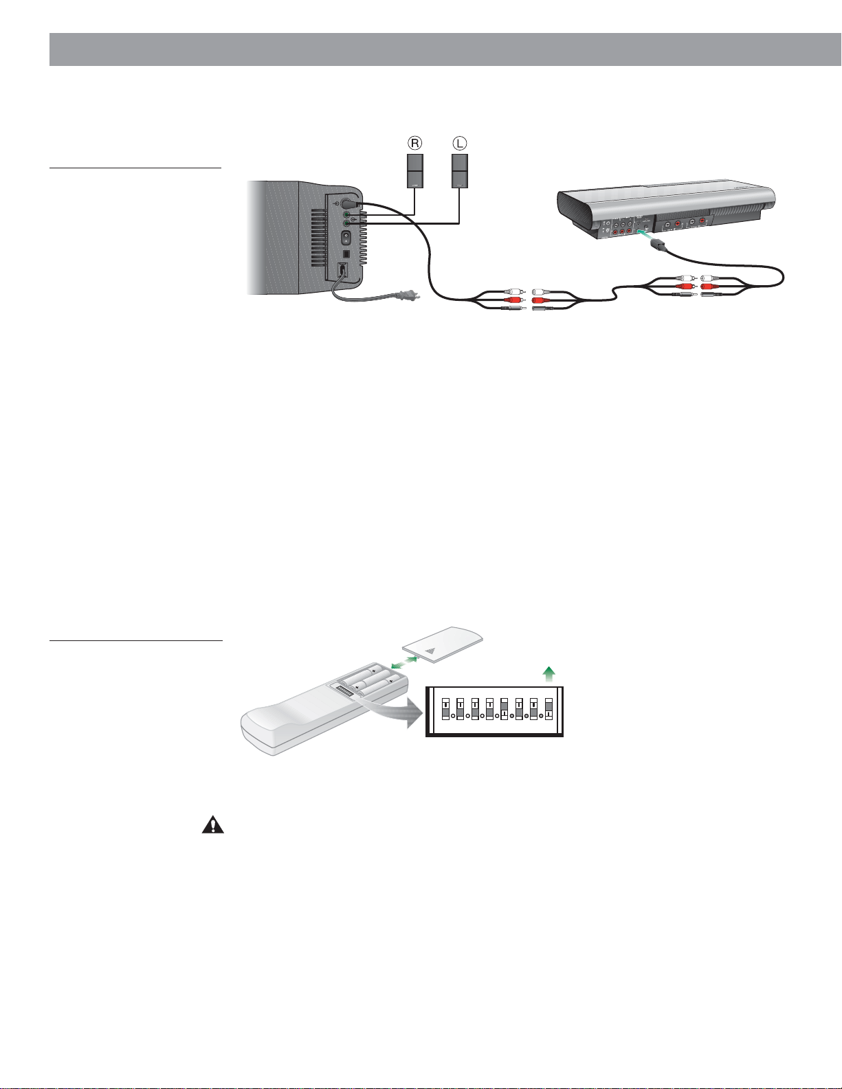
Figure 12
English
Connecting the speakers to
your model 20 music center
To connect the Acoustimass 5 or 20 powered speakers to your system, follow these steps:
1. Using the supplied 30-foot audio input cable, insert the DIN connector into the
Acoustimass module, and the RCA plug into the supplied 3-foot adapter cable (Figure 12).
2. Then, attach the DIN end of the 3-foot adapter cable to the Zone 2 output jack on the rear
of the model 20 music center (Figure 12).
3. To extend the length of the cables, use the supplied 50-foot extension cable. This cable
connects between the 30-foot audio input cable and the 3-foot adapter cable
(Figure 12).
AUDIO
INPUT
RIGHT
OUTPUTS
TO
CUBE
SPEAKERS
LEFT
OFF
POWER
ON
Figure 13
Setting up the remote control
Setting up the remote control
You need to set up a second remote control to operate the ZONE 2 outputs.
• Remove the remote control battery cover and locate the miniature switches.
• Make sure that the house code settings (switches 1, 2, 3, and 4) match those on your first
remote.
• Set switch 8 up for ZONE 2.
40
ON
234l
K
5678
Connecting power to your system
CAUTION
to the correct voltage. To do this, refer to “Selecting the correct voltage” on page 6.
Follow these steps to connect power to your Acoustimass powered speaker system:
1. Plug the power cord from the Acoustimass module into an AC power (mains) outlet.
2. Insert the power cords of the Lifestyle® system into an AC power (mains) outlet.
3. Turn the Acoustimass module power switch to the ON position.
: If you purchased a dual-voltage system, it is important that you set the speakers
12
Page 13
L
R
A
B
S
P
E
A
K
E
R
S
O
U
T
P
U
T
F
IX
E
D
M
U
S
I
C
C
E
N
T
E
R
Setting Up
Connecting the Acoustimass® module to the model 5 music center
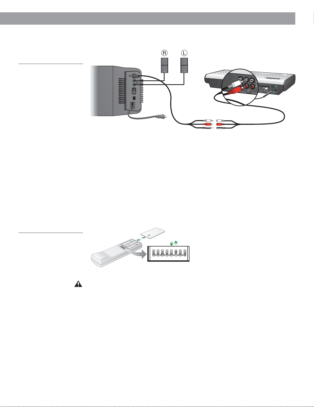
Figure 14
Connecting the speakers to your
model 5 music center
To connect the Acoustimass 5 or 20 powered speakers to your system, follow these steps:
1. Using the supplied 30-foot audio input cable, insert the DIN connector into the
Acoustimass module, and the RCA plugs directly into SPEAKERS B on the music center
(Figure 14).
2. Plug the stereo mini-plug into System Control 2.
3. To extend the length of the cables, use the supplied 50-foot extension cable.
Setting up the remote control
You need to set up a second remote control to operate the SPEAKERS B outputs.
• Remove the remote control battery cover and locate the miniature switches.
• Make sure that the house code settings (switches 1, 2, 3, 4) match those in your first
remote. Set switches 5 down and 6 up for SPEAKERS B (Figure 15).
OUTPUTS
SPEAKERS
AUDIO
INPUT
RIGHT
TO
CUBE
LEFT
OFF
POWER
ON
L
I
F
E
S
T
Y
L
E
®
M
O
D
E
L
5
M
U
S
I
C
C
E
N
T
E
R
C
O
V
E
R
E
D
B
Y
U
.
S
.
P
A
T
E
N
T
M
A
N
U
F
A
C
T
U
R
E
D
:
BOSE CORPORATI
ON, FRAMINGHAM, M
L
D
3
3
9
,
6
0
6
A 01701-9168 MADE IN U.S.A
F
I
X
E
R
A
B
S
P
E
A
K
E
R
S
O
U
T
P
U
T
F
M
7
5
Ω
L
D
R
R
E
C
P
L
A
Y
T
A
P
E
V
I
D
E
A
O
U
X
S
O
U
N
D
O
U
T
P
U
T
A
English
A
M
L
O
O
P
1
P
O
W
E
R
1
2
V
A
C
S
I
Y
N
S
T
E
M
1
.
0
A
C
O
N
T
R
O
L
2
N
T
E
N
N
A
S
E
E
I
N
S
T
R
U
C
T
I
O
N
M
A
N
U
A
L
Figure 15
Setting up the remote control
40
ON
234l
K
5678
Connecting power to your system
CAUTION
to the correct voltage. To do this, refer to “Selecting the correct voltage” on page 6.
Follow these steps to connect power to your Acoustimass powered speaker system:
1. Plug the power cord from the Acoustimass module into an AC power (mains) outlet.
2. Insert the power cords of the Lifestyle® system into an AC power (mains) outlet.
3. Turn the Acoustimass module power switch to the ON position.
: If you purchased a dual-voltage system, it is important that you set the speakers
13
Page 14

Setting Up
Fine-tuning your system
Figure 16
English
Bass and treble controls
In most situations, you only need to follow the speaker placement guidelines for your system
to provide excellent sound quality.
You do not need to adjust tone settings for changes in volume, since Bose
processing technology provides a natural tonal balance over the full range of volume settings.
If desired, you can further fine-tune your system as described below.
®
patented signal
Adjusting speaker controls
The TREBLE and BASS controls are located on the Acoustimass® 5 and 20 music systems’
Acoustimass module (Figure 16). They allow you to adjust the treble (high frequencies) and
bass (low frequencies). In the normal setting, the dots on each control are in the 12 o’clock
position. Turn the controls clockwise to increase and counterclockwise to decrease the
amount of treble or bass.
Compensating for room acoustics
The acoustics (sound qualities) of your room can affect the overall sound quality of any
speaker system. In general, you can reduce many problems with acoustics by the careful use
of the TREBLE and BASS controls.
Too much or too little treble
Rooms with too few sound-absorbing furnishings, especially those with bare floors and walls,
may sound overly shrill or “bright.” Turning down the treble control (toward –) decreases
treble sound.
Rooms with a lot of sound-absorbing furnishings, such as upholstered furniture, wall-to-wall
carpet, or heavy drapes, may reduce the treble sound of your system. Moving speakers
farther away from soft furnishings increases treble. You can increase treble sound by slightly
turning up the treble control (toward +).
Too much or too little bass
You can decrease bass sound by turning down the bass control (toward –). To increase bass,
turn up the bass control (toward +).
Acoustimass module placement affects the amount of bass you hear. Placing the module
closer to the corner of the room will increase bass. Moving the module away from the corner
will decrease bass.
14
Page 15

Product Information
Troubleshooting
Problem What to do
System does not function at all • Make sure the power connector is plugged securely into the music center, the power cord is
plugged securely into the Acoustimass® module, the power pack and power cord are
plugged into operating AC wall outlets, and the module power switch is on.
• Be sure to select a source (CD, AM/FM, etc.).
• Unplug the music center power pack for a minute, then reconnect it. This allows the unit to
reset itself after a power surge or power interruption.
No sound • Turn the music center off for ten seconds, then on again, to re-establish communication
between the music center and the speakers.
• Check the connections for any external components. Make sure to select the correct
source for the desired input.
• Check the speaker connections.
• Be sure the CD is placed correctly, label-side up, in the music center, and the cover is
closed.
• Increase the volume.
• Check to see if MUTE is lit in the display. Press MUTE on the remote to unmute the sound.
• Disconnect any headphones.
• Connect the FM and AM antennas.
English
Accessories
Customer Service
The following accessories are available to enhance the flexibility of your Bose® powered
speaker system. Contact your Bose dealer or call Bose directly (see inside back cover for
phone numbers):
UB-20: High-quality cast zinc bracket for wall or ceiling mounting.
UFS-20: Slender metal floor stands, 37"H (93.98 cm), elegantly display cube speakers
while hiding the speaker wires.
UTS-20: High-quality cast aluminum stands, 7"H (17.78 cm), for placement
on a flat surface, like a bookshelf or table.
For assistance, contact Bose customer service. See the inside back cover for customer
service offices and phone numbers.
Note:
Your Acoustimass powered speaker system should be mounted only in the manner
recommended by Bose. Consult the instructions supplied with the mounting accessories.
15
Page 16

Product Information
Technical Information
English
Power rating
USA/Canada: 120V ~ 50/60 Hz, 350W
Dual Voltage: 115/230V ~ 50/60 Hz, 350W
Europe/Australia: 220-240V ~ 50/60Hz, 350W
Dimensions
Acoustimass® 5 powered speaker system:
Cube speakers: 3.1"W x 4"D x 6.2"H (7.8 x 10.2 x 15.8 cm)
Acoustimass module: 23.3"W x 7.5"D x 14"H (59 x 19 x 35.5 cm)
Acoustimass 20 powered speaker system:
Cube speakers: 2.2"W x 3.2"D x 4.4"H (5.6 x 8.2 x 11.2 cm)
Acoustimass module: 23.3"W x 7.5"D x 14"H (59 x 19 x 35.5 cm)
Weight
Acoustimass 5 powered speaker system:
Cube speakers: 2.4 lb (1.11 kg); Acoustimass module: 33 lb (15 kg)
Acoustimass 20 powered speaker system:
Cube speakers: 1 lb (.5 kg); Acoustimass module: 33 lb (15 kg)
Finish
Cube speakers: Polymer, painted
Acoustimass module: Vinyl veneer
Warranty period
The Bose® Acoustimass 5 and 20 powered speaker systems are covered by a limited 1-year
transferable warranty. Details of the warranty are provided on the warranty card that came
with your system. Please fill out the information section on the card and mail it to Bose
Corporation.
Cleaning the Acoustimass® 5 or 20 powered speaker system
Clean the surface of your speakers with a soft, damp cloth. Do not use any sprays near the
system. Do not use any solvents, chemicals, or cleaning solutions containing alcohol, ammonia, or abrasives. Do not allow liquids to spill into any openings.
The speaker grille panels require no special care, though you may vacuum them carefully with
a soft-bristled attachment, if necessary.
16
Page 17

English
17
Page 18

USA
Bose Corporation, The Mountain
Framingham, MA 01701-9168
1-800-367-4008
Phone hours - ET (eastern time):
Weekdays 8:30 a.m. to 8 p.m.
Saturdays 9 a.m. to 3 p.m.
Canada
Bose Ltd., 1-35 East Beaver Creek Road
Richmond Hill, Ontario L4B 1B3
1-800-465-2673
Phone hours - ET (eastern time):
Weekdays 9 a.m. to 5 p.m.
European Office
Bose Products B.V., Nijverheidstraat 8
1135 GE Edam, Nederland
TEL 0299-390111 FAX 0299-390114
Australia
Bose Pty Limited 1 Sorrell Street
Parramatta NSW, 2150
TEL 02 9204-6111 FAX 02 9204-6122
Belgique/België
Bose N.V., Limesweg 2, B-3700 Tongeren
TEL 012-390800 FAX 012-390840
Danmark
Bose A/S, Industrivej 7, 2605 Brøndby
TEL 4343-7777 FAX 4343-7818
Italia
Bose S.p.A., Via della Magliana 876
00148 Roma
www.bose.iT
TEL 06-65670802 FAX 06-65680167
Japan
Bose K.K., Shibuya YT Building
28-3 Maruyama-cho
Shibuya-ku, Tokyo 150
TEL 3-5489-0955 FAX 3-5489-0592
Nederland
Bose B.V., Nijverheidstraat 8
1135 GE Edam
TEL 0299-390111 FAX 0299-390109
Norge
Bose A/S, Solheimsgate 11
N-2001, Lillestrøm
TEL 63-817380 FAX 63-810819
Österreich
Bose Ges.m.b.H., Vienna Business Park
Wienerbergstrasse 7 (10.OG)
A-1100 Vienna
TEL 01-60404340 FAX 01-604043423
Schweiz
Bose AG, Rünenbergerstrasse 13
4460-Gelterkinden
TEL 061-9815544 FAX 061-9815502
Deutschland
Bose GmbH, Max-Planck-Straße 36d
D-61381 Friedrichsdorf
TEL 06172-71040 FAX 06172-710419
France
Bose S.A., 6, rue Saint Vincent
78100 Saint Germain en Laye
TEL 01-30616363 FAX 01-30614105
India
Bose Corporation India Private Limited
W-16, Greater Kailash-II
New Delhi 110 048
TEL (011) 648 4462 FAX (011) 648 4463
Ireland
Bose Corporation
Carrickmacross, Co Monaghan
TEL (042) 9661988 FAX (042) 9661998
Sverige
Bose A/S, JohanneFredsgatan 4
S-43153 Mölndal
TEL 31-878850 FAX 31-274891
United Kingdom
Bose Limited
1 Ambley Green
Gillingham Business Park
Gillingham, Kent ME8 ONJ
TEL 0870-741-4500 FAX 0870-741-4545
From other locations
Bose Customer Service, 1 New York Ave.
Framingham, MA 01701-9168 USA
TEL (508) 766-1900 FAX (508) 766-1919
World Wide W eb
www.bose.com
Page 19

©2004 Bose Corporation
The Mountain, Framingham, MA 01701-9168 USA
256193-ENGvo AM Rev.00
 Loading...