

Page 1
Page 2
The Bose 60T“ Series Hi Direct/ReTiecting® Loudspeaker System
l^€
Before you begin...
Thank you for purcliasing the Bose'“’' 601 Series ill
Direct/Reflecling''^ Loudspeaker System. We are con
fident that Its advanced technology and quality con^ruction will provide you with a lifetime of musical
listening pleasure.
The opiating principles of your Bose 601 system
are significantly different from those of conventional
speakers. To obtain Uie best possible results, please
take the time to read this cwner's guide.
I. Unpacking Your Bose 601 System
After opening the cartons, remove all packing ma
terial and carefully lift out each speaker. If either
speaker appears to be damaged, do not attempt to
use it. Instead, repack the speaker in its original
carton and notify your authorized Bose dealer
immediately.
Saw the cartons and packing material tn case the
speakers need to be transported at a later time.
II. Setting Up Your Bose 601 Speaker
System
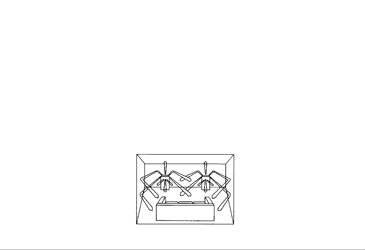
Unlike conventional speakers, the Bose 601 system is
designed to reflect sound energy off the walls, floor
and ceiling of your listening room (see Figure 1).
The Bose 601 system has been designed to sound
equally good in a variety of room settings and
arrangements.
Select the wall where you intend to place the speak
ers. The60l speakers will give excellent performance
when placed either along a short or long wall in your
room. Place one speaker on the left side ot the wall
and the other speaker on the right side. Then refer
to the guidelines below to obtain maximum perfor
mance from your speakers.
A. For best results, positior^ your speakers at least
18 inches (45 cm) from the side walls. Recom
mended distance is 2 to 5 feet (0.6-1.5 m) from
the side wails. Avoid placing large objects (such as
furniture) in front of the speakers.
B. The greatest amount of bass response is obtained
when the speakers are set about half an inch from
the wall behind them. However, you can place the
speakers up to 12 inches (30 cm) away from the
rear reflecting wall and ^ill obtain satisfactory
performance.
C. In average-sized listening rooms, the best ster
eophonic effects result when the speakers are
spaced 6 to 12 feet apart (1.8-3.6 m). However, you
can still achieve excellent results with separation as
little as3 feet (i m) or as great as 15 feel (4.5 m).
0. ft is Important not to block or cover the
acoustically-transparent grille panels for two
reasons: first, a large proportion of the sound
energy produced by your 601 speakers radiates
through the top of the enclosure and should not be
blocked. Second, the grille assemblies of the 601
speakers are cosmetic and are not designed to
Figure 1. The listening area produced by the Bose
601-111 speaker system
support v/eight. The Free Space’^ tweeter array
locked beneath the top grille is a precision assem
bly and could potentially be damaged by objects
placed on top of die speai^r.
Hi. Selecting the Proper Wire
For connecting your speakers, we recommend using
standard zipcord, the wire most commonly carried by
audio dealers and electrical stores. This wire is often
color-coded, or else has a ribbed line(s) running
along one conductor so that each conductor can
be easily identified for proper connection of your
speakers.
A minimum of 18-gauge zipcord is recommended for
lengths up to 30 feet per speaker: 16-gauge for up to
45 feel, and 14-gauge for up to 70 feet. If the wire con
necting the speaters to your amplifier is too smalt,
audible coloration of the sound and/or power loss can
occur. Your Bose dealer can provide further assis
tance regarding speaker wire selection.
IV. Connecting Your Bose 601 Speakers
Before attempting to connect the loudspeakers,
unplug your receiver or amplifier from the wail
outlet. Then follov/ the steps below.
NOTE: The Bose 601 system is an 8 ohm speaker
and may safely be connected in parallel with arKrther
8 crfim speaker with most amplifiers. Consult your
receiver or amplifier's User Guide before connecting
multiple speakers, or consult your Bos© dealer.
A. Measure the amount of wire required for each
speaker and cut it accordingly. If possible, try to
teep both speaker wires roughly the same lengtfi.
B. Each half of the wire is aconductor. Separate the
conductors at both ends by pulling the wire apart
several inches. Strip off approximat^y Yainch
(12 mm) of insulation from each conductor.
Page 3

Examine the wire ends carefully. There will be
some visible difference between the two conduc
tors. If the wire is clear, one side may be silver and
the other copper. If the wire is not color coded,
one side will be ribbed or striped. Consider the
ribbed, striped or copper side to be positive
(-f). The remaining side (plain, smooth, or
silver) is negative (-).
STEREO AMPLIFIER OR RECEIVER
Figure 2. Connecting the speaker
C. Connect the negative side of one wire to the termi
nal marked (-) on the left speater. Refer to Fig
ure 2. Connect the other negative end of the sane
(negative) wire to the corresponding negative ter
minal on the left channel of your receiver or ampli
fier. Refer to Figure 3.
D. In the same way. connect the positive terminal (-i-)
of Ore left speaker to the corresponding positive
terminal on the left receiver or amplifter channel.
(If your receiver or amplifier offers a choice of
output impedances, use the terminal marked 8
or 8 OHMS.)
E. Using the other piece of wire, repeat steps C and
D above to connect the right speaker to the right
channel of your receiver oranplifier
F, Check very carefully to make sure that no loose
strands of wire are brushing against the other ter
minal on either the speaker or ^plifier/receiver.
Such "bridged" wires create short circuits which
can damageyouramptitieryreceiver. Repair any
Figure 3. Connecting the speaker to the receiver
or amplifier
loose wire strands before plugging in your
amplifier or receiver.
PLEASE NOTE: Care is required if you intend to sta
ple speaker wires. It a staple or other object pierces
the wire, it could cause a short circuit.
V. Checking Your Hookup
If you are not sure whether the speakers are correctly
hooked up or in phase (positive to positive, negative
to negative), try this simple test.
A. Set your sound system for MONO (monophonic or
L -F R) reproduction, Be sure the balance control is
centered or set to normal.
B. Turn and move the speakers so they are facing
each other very closely.
C. Play some music with deep bass. If the speakers
are hooked up correctly, the sound svill come from
a point between the speakers and will have full,
nature bass response.
If the music is not loc^ized between the two speak
ers and/or you do not hear much deep bass, shut
the receiver or amplifter off, reverse the (+) and
(-) connections on one speaker only, and repeat
the test. Use the connection which produces the
most bass.
VI. Getting the Most Out of Your Bose
601 Speaker System
Once set up and connected property, your speakers
will require very little attention. However, observing
the following guidelines will help you get the most out
of your speaker investment.
A. Fusing
Any loudspeaker can be damaged if the amplifier
driving it should fail or is played so loudly that it
produces distortion. This is especially litely to
occur with low-powered amplifiers or receivers.
Your 601 speakers have Digital Dynamic Range'
woofers with built-in woofer protection circuitry. For
maximum protection, however, we recommend
fusing.
A fuse can be inserted into the speaker circuitry by
simply wiring a fuseholder to the (-i-) terming^ of the
speaker. The speaker wire then connects to the
holder, putting the fuseholder between the speak
er’s (+) terminal and the receiver or amplifier’s (+)
terminal. Wtien the fuse is Inserted into the fuse-
holder. the fusing protection system is complete.
2-ampere. tast-Wow Buss AGC Series or Littlefuse
AG Series fuses are recommended.
Page 4

A fuse kit containing fuses arxl hoklers is availabfe
from the Bose^ Customer Service Oepartnwnt. 78
Turnpike Road. Weslborough. MA 01 $81 *9168 for
$7.50. Ask for Pan Number 108938-2.
B. Room Acoustics
Where you place your 601 speakers in your room is
important for getting the best sound. There is no
one required placement position: rather, it is impor
tant to know that ptacement does affect sound.
Your 601 system works best when sound energy is
allowed to develop “around" the speakers, reltoctingoff nearby wailsandfloormg. We recommend
that you experiment with various locations and
put the speakers where they sound bea to you
before determining final ptacement. The followirtg tips will help you maximize the sound of your
601 speakers.
1. Hard materials such as wood, brick, glass,
sheelrock. and/or heavy paneling generally
provide Uie most effective sound reflecting
surfaces.
2. Rooms with a lot of sound absorbing furnishings
(stuffed furniture, wall-to-wall carpets, heavy
drapes, etc.) may reduce the treble sound of
your system, making it sound dull. This treble
can be restored by removing some of the
absorbent furnishings from the immediate
vicinity of the speakers.
3- Rooms with few sound absorbing furnishings,
especially those with bare floors and walls, may
sound overly ^riltor "bright." Adding sound
absorbers such as thrcKv rugs or drapes will
usually solve this problem. For best results,
scatter these furnishings evenly around Ihe
listening area.
4. If your music seems to lack bass, try moving
the speakers a little doser to the rear wall and/or
the comers of the room. Excess bass can be
reduced by moving the speakers away irom cor
ners and v/alls. The closer the speakers are to
the intersection of the room boundaries (such as
the corner, where two walls intersect each other
and the floor), the more bass they will produce.
By keeping this in mind, you can tune your sys
tem to your listening environment.
5. Many acoustical problems can be solved by the
judicious use of your receiver or amplifier's tone
controls. Experiment wilfi different sellings to
achieve a frequency balance that suits the
acoustics of your listening room. Remember,
though, tfiat the use of these controls may
pul greater power demands on your receiver
or amplifier. Excessive use of tone control
can cause a receiver or amplifier to run out
of power and distort, potentially damaging
your entire system.
C- Matnlenar>ce
The finish on your 601 speakers is a genuine hard
wood veneer with a walnut finish. As with any other
piece of fine furniture, only a high quality furniture
polish should be used on the cabinets. Soap,
water, or any household cleaners should be
avoided.
The 601 speaker has an acoustically transparent
grille assembly attached to the enclosure with
snap-type fasteners. The grilles may be removed
and carefully vacuumed if necessary. Remove
and replace grilles carefully to avoid damag
ing front tweeters. To remove the grille assemWy.
gently pry the bottom section away from the cabi
net with your fingers. Then lift the top section off the
cabinet. To replace the grille, reverse this proce
dure. Do not use sharp objects to pry off the
grille as this might damage both the grille and
the enclosure.
CAUTION: Avoid placing objects on, or spilling
liquids into your 601 speakers. This type of dam
age will NOT be covered under warranty.
VII. In Case You Have a Problem
H you experience any difficulty with your 601 system,
try the following sim^e test procedures first to deter
mine if the speakers are at fault. The majority of audio
problems generally occur in components other than
speakers.
A. If one speaker sounds defective (does not pfay
or plays distorted sound) shut the receiver
or amplifier off. Disconnect both wires at the
receiver or amplifier’s output. Reconnect the
defective speaker to the receiver or amplifier ter
minals that had been connected to the “good”
speaker. If the “defective" speaker now sounds
correct, the problem Is not with the speaker. Do
not connect the normal sounding speaker
to a possibly defective receiver or amplifier
channel under any circumstances. Make
sure you check all wiring for loose conneclions
and/or shorts.
If both speakers sound defective, connect them to
another receiver or amplifier that is working prop
erly. If the speakers now operate correctly, the
proWem is not in the speakers.
If trouWe persists in one or both speakers, contact
your authorized Bose dealer. He will verify any
defects and arrange for service by an authorized
service agency or by the Bose factory. Bose
Corporation will make every effort to remedy any
problem within the terms of the warranty at mini
mum inconvenience to you.
Page 5

VIII. Technical information
Features:
Oirect/Reftecting® system design
Free Space® array
Subporl enclosure system with slotted port
Digital Dynamic Range® woofers
Dual Frequency"'* crossover network
Automatic woofer protection circuit
Syncom® II computer quality control
Acoustically transparent grille assembly (removable)
Full five-year warranty
Driver Complement: Two (2) 8" (20 cm) longexcursion Digital Dynamic Range woofers. Four (4)
3" (76 mm) high-sensitivity tweeters.
Nominal Impedance: 8 ohms
Amplifier Power Requirements: Minimum; 10
watts per channel. Maximum: 200 watts RMS maxi
mum per channel, conforming to lEC specifications.
Fusing: Series-connected 2A fast-blow fuse recom
mended.
Cabinet: Genuine hardwood veneer with walnut
finish.
Dimensions: I2^i© Wx12Vi D x30 H inches (3089
x31.75x 76.2 cm)
Weight: 45 lbs (20.41 kg)/speaker
Page 6

Covered by paiem r i^is ssuod arxVor porKJina {601 speaKor
design isa trademark of BoseCorporaion) ©Cow'*9^f ^986 Bose
Corporation. Al rights reserved Printed in USA. SpeciliealionsarKV
or features subject to change wAhoui rxiticc
Better sound through research
Bose Corporation, The Mountain
Framingham. Massachusetts 01701 -9i 68 USA
Australia, Belgium. Canada. Denmark. England.
France. Germany, Ireland, Italy. Japan. Netherlands,
Puerto Rico, Spain, Switzerland
PN128800
 Loading...