

Page 1

The Bose® Lifestyle® 50 System
Owner’ s Guide
October 17, 2001
AM189854_05_V.pdf
Page 2

Safety Information
WARNING:
To reduce the risk of fire or electric shock, do not expose the system to rain or
moisture.
CAUTION
RISK OF ELECTRICAL SHOCK
DO NOT OPEN
CAUTION: TO REDUCE THE RISK OF ELECTRIC SHOCK,
DO NOT REMOVE COVER (OR BACK).
NO USER-SERVICABLE PARTS INSIDE.
REFER SERVICING TO QUALIFIED PERSONNEL.
RISQUE DE CHOC ÉLECTRIQUE
AFIN DE PRÉVENIR UN CHOC ÉLECTRIQUE NE PAS ENLEVER
LE COUVERCLE ARRIÈRE. IL NE SE TROUVE À L’INTÉRIEUR
AUCUNE PIÈCE POUVANT ÊTRE RÉPARÉE PAR
L’USAGER. S’ADRESSER À UN RÉPARATEUR COMPÉTENT.
AVIS
NE PAS OUVRIR
These CAUTION marks may be located on the bottoms of your Lifestyle® Personal® music
center, Acoustimass® module, multi-room interface, and CD changer:
The lightning flash with arrowhead symbol, within an equilateral triangle, is intended to alert
the user to the presence of uninsulated dangerous voltage within the system enclosure that
may be of sufficient magnitude to constitute a risk of electric shock.
The exclamation point within an equilateral triangle, as marked on the system, is intended to
alert the user to the presence of important operating and maintenance instructions in this
owner’s guide.
CAUTION:
To prevent electric shock, match wide blade of plug to wide slot, insert fully.
Class 1 laser product
This compact disc player is classified as a CLASS 1 LASER PRODUCT. The CLASS 1 LASER PRODUCT label is located on the bottom
of the unit.
CLASS 1 LASER PRODUCT
KLASSE 1 LASER PRODUKT
LUOKAN 1 LASER LAITE
KLASS 1 LASER APPARAT
CAUTION:
Use of controls or adjustments or performance of procedures other than those
specified herein may result in hazardous radiation exposure. The compact disc player should
not be adjusted or repaired by anyone except properly qualified service personnel.
Class B emissions limits
This Class B digital apparatus meets all requirements of the Canadian Interference-Causing
Equipment Regulations.
Batteries
Please dispose of used batteries properly, following any local regulations. Do not incinerate.
Additional safety information
See the additional instructions on the Important Safety Information page enclosed with this
owner’s guide.
Please read this owner’s guide
Please take the time to follow this owner’s guide carefully. It will help you set up and operate
your system properly, and enjoy all of its advanced features. Save your owner’s guide for
future reference.
Product manufactured under license from Dolby Laboratories, Inc. “Dolby” and the double-D symbol are trademarks of Dolby Laboratories, Inc.
2 October 17, 2001 AM189854_05_V.pdf
Page 3

Important Safety Instructions
1. Read these instructions – for all components
before using this product.
2. Keep these instructions – for future reference.
3. Heed all warnings – on the product and in the
owner’s guide.
4. Follow all instructions.
5. Do not use this apparatus near water or
moisture – Do not use this product near a
bathtub, washbowl, kitchen sink, laundry tub, in a
wet basement, near a swimming pool, or anywhere else that water or moisture are present.
6. Clean only with a dry cloth – and as directed
by Bose® Corporation. Unplug this product from
the wall outlet before cleaning.
7. Do not block any ventilation openings.
Install in accordance with the
manufacturer’ s instructions – To ensure
reliable operation of the product and to protect it
from overheating, put the product in a position
and location that will not interfere with its proper
ventilation. For example, do not place the product
on a bed, sofa, or similar surface that may block
the ventilation openings. Do not put it in a built-in
system, such as a bookcase or a cabinet that may
keep air from flowing through its ventilation
openings.
8. Do not install near any heat sources, such
as radiators, heat registers, stoves or other
apparatus (including amplifiers) that produce heat.
9. Do not defeat the safety purpose of the
polarized or grounding-type plug. A polar ized plug has two blades with one wider
than the other . A grounding-type plug has
two blades and a third grounding prong. The
wider blade or third prong are pr ovided for
your safety . If the provided plug does not fit
in your outlet, consult an electrician for
replacement of the obsolete outlet.
10. Protect the power cord from being walked
on or pinched, particularly at plugs, convenience receptacles, and the point where
they exit from the apparatus.
11. Only use attachments/accessories specified by the manufacturer .
12. Use only with the cart, stand, tripod,
bracket or table specified by the
manufacturer or sold with the
apparatus. When a cart is used,
use caution when moving the
cart/apparatus combination to
avoid injury from tip-over .
13. Unplug this apparatus during lightning
storms or when unused for long periods of
time – to prevent damage to this product.
14. Refer all servicing to qualified service personnel. Servicing is required when the apparatus
has been damaged in any way: such as powersupply cord or plug is damaged; liquid has
been spilled or objects have fallen into the
apparatus; the apparatus has been exposed to
rain or moisture, does not operate normally , or
has been dropped – Do not attempt to service this
product yourself. Opening or removing covers may
expose you to dangerous voltages or other hazards.
Please call Bose to be referred to an authorized
service center near you.
15. T o prevent risk of fir e or electric shock, avoid
overloading wall outlets, extension cords, or
integral convenience receptacles.
16. Do not let objects or liquids enter the product –
as they may touch dangerous voltage points or
short-out parts that could result in a fire or electric
shock.
17. See product enclosure for safety related
markings.
Information about products that
generate electrical noise
If applicable, this equipment has been tested and found
to comply with the limits for a Class B digital device,
pursuant to Part 15 of the FCC rules. These limits are
designed to provide reasonable protection against
harmful interference in a residential installation. This
equipment generates, uses, and can radiate radio
frequency energy and, if not installed and used in accordance with the instructions, may cause harmful interference to radio communications. However, this is no
guarantee that interference will not occur in a particular
installation. If this equipment does cause harmful interference to radio or television reception, which can be
determined by turning the equipment off and on, you are
encouraged to try to correct the interference by one or
more of the following measures:
• Reorient or relocate the receiving antenna.
• Increase the separation between the equipment and
receiver.
• Connect the equipment to an outlet on a different
circuit than the one to which the receiver is connected.
• Consult the dealer or an experienced radio/TV techni-
cian for help.
Note:
Unauthorized modification of the receiver or radio
remote control could void the user’s authority to operate
this equipment.
This product complies with the Canadian ICES-003 Class
B specifications.
AM189854_05_V.pdf October 17, 2001 2a
Page 4

Important Safety Instructions
18. Use proper power sources – Plug the product into
a proper power source, as described in the operating
instructions or as marked on the product.
19. Avoid power lines – Use extreme care when
English
installing an outside antenna system to keep from
touching power lines or circuits, as contact with
them may be fatal. Do not install external antennas
near overhead power lines or other electric light or
power circuits, nor where an antenna can fall into
such circuits or power lines.
20. Ground all outdoor antennas – If an external
antenna or cable system is connected to this
product, be sure the antenna or cable system is
grounded. This will provide some protection against
voltage surges and built-up static charges.
Section 810 of the National Electrical Code ANSI/
NFPA No. 70 provides information with respect to
proper grounding of the mast and supporting
structure, grounding of the lead-in wire to an antenna
discharge unit, size of grounding conductors,
location of antenna-discharge unit, connection to
grounding electrodes, and requirements for the
ground electrode. Refer to the antenna grounding
illustration on this page.
Antenna grounding
Example of antenna grounding as per National Electrical
Code, ANSI/NFPA 70.
Antenna lead in wire
Ground clamp
Electric service
equipment
Ground clamps
Power service grounding
electrode system
(NEC ART 250, Part H)
Antenna discharge unit
(NEC Section 810-20)
Grounding conductors
(NEC Section 810-21)
Note to CATV system installer
This reminder is provided to call the CATV system
installer’s attention to Article 820-40 of the NEC (of USA)
that provides guidelines for proper grounding. In particular, it specifies that the cable ground shall be connected
to the grounding system of the building, as close to the
point of cable entry as is practical.
2b October 17, 2001 AM189854_05_V.pdf
Page 5

Where to find …
Contents
Setting Up .............................................................................................................................4
Before you begin.............................................................................................................4
Unpacking the carton .................................................................................................... 5
Selecting the locations for your Lifestyle® 50 system .................................................... 6
Connecting your system .................................................................................................9
Connecting your home theater components to the Lifestyle® 50 system ....................12
Connecting other external components .......................................................................15
Connecting the antennas ..............................................................................................16
Connecting power to your system ................................................................................17
Setting up the Personal™ music center .......................................................................17
Operating Your Lifestyle® 50 System ..................................................................................18
Turning on the system .................................................................................................. 18
Using the Personal™ music center display ..................................................................20
Listening to the system .................................................................................................22
Listening to digital sound..............................................................................................24
Operating the special features ......................................................................................25
Listening to the radio ....................................................................................................26
Listening to compact discs ...........................................................................................29
Using the system with external components................................................................35
Fine-tuning your system ...............................................................................................36
Operating a Multi-Room Lifestyle® 50 System ....................................................................40
Connecting additional rooms........................................................................................40
Operating in more than one room.................................................................................41
Using more than one Personal™ music center ............................................................43
Maintaining Your Lifestyle® 50 System...............................................................................44
Finding a misplaced Personal™ music center ............................................................. 44
Replacing batteries .......................................................................................................44
Cleaning the system .....................................................................................................45
Troubleshooting ............................................................................................................46
Warranty period ............................................................................................................47
Customer Service .........................................................................................................47
Product Information.............................................................................................................48
Technical information ....................................................................................................48
Accessories...................................................................................................................48
Index ....................................................................................................................................49
Bose® Corporation ..................................................................................... Inside back cover
Español Fran
çais
For your records
Serial numbers are located on the bottom panels of the Personal music center, multi-room
interface, CD changer, and the Acoustimass® module.
Personal music center serial number: _____________________________________________
Multi-room interface serial number: _______________________________________________
CD changer serial number: ______________________________________________________
Acoustimass module serial number: ______________________________________________
Dealer name: __________________________________________________________________
Dealer phone:_______________________ Purchase date: ___________________________
We suggest you keep your sales slip and warranty card together with this owner’s guide.
AM189854_05_V.pdf October 17, 2001 3
Page 6

Setting Up
Before you begin
Thank you for purchasing the Bose® Lifestyle® 50 system. Years of research lie behind this
complete audio home entertainment system – the most advanced home theater system from
Bose. Technological innovations that make the Lifestyle® 50 system unique include the Bose
Personal™ music center, which places all system operations in the palm of your hand, and
tiny Jewel Cube® speakers.
The interactive Personal music center is a clear departure from convention, communicating
with the system through a two-way radio data link. The result for you is full control of this
entertainment system as you move about your home.
The Bose Jewel Cube speakers are also far from conventional. Proprietary technologies
ensure that these tiny speakers not only fill a room with sound, but also reproduce it more
accurately than traditionally designed loudspeakers.
The other elements of the Lifestyle® 50 system are designed to be hidden from view:
• The elegant Lifestyle® CD changer, designed to give you flexibility in where it is placed
• The hideaway powered Acoustimass® module that delivers the rich, full, lifelike bass
• The Bose multi-room interface, with four independent audio outputs that allow you to
enjoy Bose sound throughout your home.
Realism and impact
Your Lifestyle® 50 system is equipped with an all new Videostage® decoder that uses digital
signal processing. The result is increased surround sound realism and impact both for movie
soundtracks and music recordings. The Videostage decoder processes analog formats, as
well as two or even single-channel PCM and Dolby Digital bitstreams, and helps to deliver the
acoustic experience of the movies right in your home.
Compatibility
Your system is fully compatible with:
• Digital-audio bitstreams. Look for the symbol 1 or the terms Dolby Digital or
PCM on DVD-Video disks. Your Lifestyle® 50 system cannot process MPEG-2 or DTS
digital bitstreams.
• Surround-sound sources such as VCRs, stereo TVs, cable boxes and satellite
receivers. Videostage decoding directs stereo information to the surround channels, so
the sound of stereo broadcasts and rented or recorded tapes can approach that of
your DVD disks.
• Surround-encoded analog or digital audio signals. Look for the terms Surround or
Dolby Surround, or the symbol 3 on tapes and discs, and the word “sur-
round” preceding a TV broadcast.
• Stereo program material from TV, FM, CD and cassette. Videostage decoding
delivers five channels, even when the original source contained only one or two.
• Monoaural program material. Videostage decoding can process a one-channel
program into five-channel sound and direct the result to five independent speakers.
Dialogue remains locked on-screen, while music and ambient effects fill the room.
Automatic sound level monitoring and control
Your enjoyment of movies is enhanced by Digital Dynamic Range® compression. This technology automatically monitors and adjusts the volume to let you to hear soft sounds, particularly
dialogue, but prevents you from being overwhelmed by loud special effects. This is especially
useful for late night viewing – it eliminates the need to constantly adjust the volume.
4 October 17, 2001 AM189854_05_V.PDF
Page 7

T
H
E
B
O
S
E
L
I
F
E
S
T
Y
L
E
M
U
S
I
C
S
Y
S
T
E
M
C
D
Unpacking the carton
Carefully unpack your system. Save all packing materials for possible future use. The original
packing materials provide the safest way to transport your Lifestyle® 50 system. If any part of
the product appears damaged, do not attempt to use the system. Notify Bose® or your
authorized Bose dealer immediately.
Check to be sure your Lifestyle
Note:
room interface, CD changer, and Acoustimass® module. Then write them on your warranty
card and in the spaces provided on page 3.
CAUTION:
removed before setting up the system.
WARNING:
to avoid injury.
WARNING:
children.
Figure 1
What comes with your
Lifestyle
• Personal music center
• CD changer
• Multi-room interface
• Interface power pack*
• 5 Jewel Cube
• 5 speaker cables
• Acoustimass module
• AC power (mains) cord*
• 14 self-adhesive rubber feet
• Audio input cable
• CD changer cable
• Stereo cable
• 4 AAA batteries
• FM antenna
• AM loop antenna
• AM antenna base
• CD magazine
• Lifestyle
• Test CD
®
50 system:
®
speakers
(4 for the module and 5 pairs for
the Jewel Cube speakers)
®
system CD
Rubber feet
CD changer cable
Setting Up
®
50 system contains the parts identified in Figure 1.
Find the serial numbers on the bottom panels of the Personal™ music center, multi-
Be sure the three shipping screws on the bottom of the CD changer have been
The Acoustimass module weighs 33 pounds (15 kg). Use good lifting practice
To avoid danger of suffocation, keep the plastic bags out of the reach of
Personal™ Music Center
Rubber feet (4)
Interface power pack
®
CD changer
6
6
5
5
4
4
3
3
2
2
1
1
6
D
IS
K
M
A
G
A
Z
IN
E
CD magazine
Antenna
base
Stereo cable
Multi-room
interface
AM loop antenna
FM antenna
Jewel Cube
speakers
(5 pairs)
Front speaker cables (blue connectors)
Acoustimass module
AC power cord
Audio input cable
Surround speaker cables (orange connectors)
Test CD
Lifestyle® system CD
AAA
batteries
(4)
*
Power cord and pack shown above are USA/Canada/Japan versions.
Dual voltage systems include 1 power cord, 1 adapter , and 2 power packs.
The power cords and packs for Europe, UK/Singapore, and Australia are shown below.
Europe
AM189854_05_V.PDF October 17, 2001 5
UK/Singapore
Australia
Page 8

Setting Up
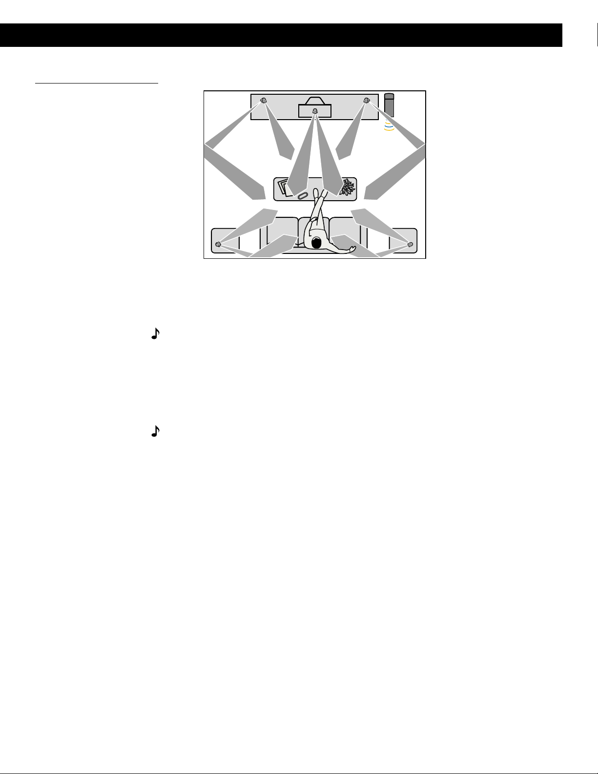
Selecting the locations for your Lifestyle® 50 system
When you place your speakers according to the guidelines below, a combination of reflected
and direct sound provides the audio atmosphere of a home theater. You may experiment with
the placement and orientation of the Jewel Cube® speakers and Acoustimass® module to
produce the sound most pleasing to you. For more discussion of speaker placement and
room acoustics, see “Fine-tuning your system” on page 36.
Jewel Cube speakers
Follow these guidelines to select locations that provide the maximum home theater effect
from your Lifestyle® 50 system (Figures 2 and 3).
CAUTION:
cause the speakers to move, particularly on very smooth surfaces. For stability, peel off the
backing from the two identical rubber feet and center them in the matching shapes on the
bottom of each speaker.
Left and right front speakers
The sound from the left and right front speakers should seem to appear at the edge of the
picture, so that the acoustic image is close to the size of the visual image (Figure 2). The front
speaker cables allow up to 20 feet (6.1 m) from the Acoustimass module.
1. Place the left and right front speakers so that they line up with the center of the TV screen.
2. Place them up to 3 feet (1 m) from the edge of the TV screen.
We recommend the 3-foot (1 m) maximum distance so that the sound does not become
too separated from the picture. You may wish to vary this distance based on room conditions and personal preference.
3. Direct one cube of each speaker forward. Direct the other cube toward the wall or in a
different direction to create reflected sound. See the illustration of suggested reflected
sound patterns in Figure 3.
Note:
the TV without affecting picture quality.
Choose a stable and level surface for your Jewel Cube speakers. Vibration can
The Jewel Cube speakers are magnetically shielded so you can place them close to
Figure 2
Recommended front speaker
locations
Left front
Center
Right front
®
6 October 17, 2001 AM189854_05_V.PDF
Page 9
Setting Up
Figure 3
Speaker placement
®
Right
surround
Left
surround
Left
front
Center
Right
front
Acoustimass
module
Center speaker
The sound from the center speaker should appear to come directly from the center of the
picture (Figure 2). The center speaker cable allows up to 20 feet (6.1 m) from the Acoustimass
module.
Note:
Do not place the speaker on its side, as this diminishes performance by blocking the
Jewel Cube ports.
1. Place the center speaker directly above or below the center of the TV screen, or at the
closest convenient location.
2. Align the speaker with the front of the TV screen (not pushed to the back of the TV).
3. Direct each cube speaker slightly away from center, to create a wider area of direct sound
(Figure 3).
Note:
If you put the speakers in a bookcase unit, be sure to place each one at the front
edge of the shelf. Placing speakers in an enclosed space can change the tonal quality of the
sound. This effect is minimized if the shelves are filled with books.
Surround speakers
The surround (rear) speakers create an area of sound around the listener. Place them in the
back half of your room. The surround cables allow up to 50 feet (15.2 m) from the
Acoustimass module.
1. Place the speakers at ear height or higher, if possible.
2. Adjust the rear surround speakers to direct the sound to the front and back of the listener
(Figure 3).
AM189854_05_V.PDF October 17, 2001 7
Page 10

Setting Up
Figure 4
Acoustimass module positions
Acoustimass® module
Follow these guidelines to select a location for the Acoustimass module.
Note:
18 inches (45 cm) from the TV.
1. Place the Acoustimass module along the same the wall or close to the same end of the
2. Select a convenient location – under a table, behind a sofa. Do not allow furniture or
3. Place the Acoustimass module within reach of the audio input cable, speaker cables, and
4. Select a position for the Acoustimass module (Figure 4). For proper ventilation, place it on
To avoid interference with the TV picture, place the Acoustimass module at least
room as the Jewel Cube® speakers (see the example along the front wall in Figure 3).
drapes to block the ventilation openings of the module.
an AC power (mains) outlet.
the long edge, with the connectors facing the floor. An alternate position is on its largest
side, with the bass and treble controls facing up. Do not place the module on either end,
as shown by the last two views in Figure 4.
®
R
I
G
H
T
R
I
G
H
T
F
R
O
N
T
R
E
A
Preferred
position
®
T
r
e
b
l
e
B
a
s
s
Alternate position
®
R
L
E
F
T
C
R
E
E
N
A
T
R
E
R
L
E
F
T
F
R
O
N
T
O
U
T
P
U
T
S
T
O
C
U
B
E
S
P
E
A
K
E
R
S
Figure 5
The multi-room interface
®®
5. Once you have selected a position for the module, place the four self-adhesive rubber feet
near the corners of the bottom surface. The rubber feet provide increased stability and
protection from scratches.
6. Aim the port (the round opening) into the room or along the wall to avoid blocking the port
or creating too much bass.
7. For best bass performance, do not place the port at equal distances from any two walls or
from a wall and the ceiling.
CAUTION:
Do not cover the ventilation openings of the Acoustimass module. The slots on
the end provide ventilation for the built-in electronic circuitry, and should not be blocked.
CAUTION:
The magnetic field from the Acoustimass module is not an immediate risk to
your video tapes, audio tapes, and other magnetic media. However, you should not store
tapes directly on or near the Acoustimass module.
Multi-room interface
Select a location for the multi-room interface. It may be placed out of sight if you like.
1. Place the multi-room interface within 30 feet (9.1 m) of the Acoustimass module (the
length of the audio input cable).
2. Place the multi-room interface close enough to the sound sources (TV, VCR, DVD, etc.) to
allow for cable length. If you need additional audio and/or video cables to connect all of
your components, see your dealer or call Bose® Customer Service.
CD changer
Figure 6
The CD changer
8 October 17, 2001 AM189854_05_V.PDF
Select a convenient location for the CD changer.
1. Place the CD changer on a level surface. Allow enough room to lift the door.
2. Place the CD changer close enough to the multi-room interface to allow for cable length
of 6 feet (2 m).
Page 11

Connecting your system
Once you have selected locations for your speakers, CD changer, and interface, connect the
system.
CAUTION:
begin hooking up the system.
Connecting the Jewel Cube® speakers to the Acoustimass
module
1. Match each cable to the corresponding speaker location.
• Front speaker cables have blue RCA connectors at one end, with L, R, or C molded
into both the RCA connectors and the Jewel Cube connectors at the other end.
• Surround speaker cables have orange RCA connectors at one end, with L or R molded
into both the RCA connectors and the Jewel Cube connectors at the other end.
2. Insert the Jewel Cube connector of each cable fully into the jack on the rear of one of the
five speakers (Figure 7). Match the ridge of the connector to the notch at the top of the
jack.
3. Connect each cable to the corresponding jack on the Acoustimass module (Figure 8).
• Plug the blue connectors into the matching left front, center, and right front jacks.
• Plug the orange connectors into the matching left surround and right surround jacks.
To lengthen the cable, connect speaker wire with male phono (RCA) plugs on each end to
your supplied speaker cable. Use a female-to-female adapter (“barrel” connector). Or, splice
in 18-gauge (.75 mm2) or thicker cord (connecting + to + and – to –). To purchase extension
wire, see your dealer or electronics store, or call Bose® Customer Service.
Setting Up
Make sure all components are unplugged from the power outlet before you
®
Figure 7
Connecting speaker cables to
Jewel Cube speakers
Ridge
Notch
AM189854_05_V.PDF October 17, 2001 9
Page 12

Setting Up
Connecting the Acoustimass® module to the multi-room interface
Connect the module to the interface with the audio input cable (Figure 8).
1. Insert the right-angle multi-pin connector on the audio input cable into the AUDIO INPUT
jack on the module. Align the connector at the angle shown in Figure 8.
2. Plug the small black multi-pin connector (flat side facing up) into the jack marked ROOM A
(PRIMARY) on the back of the interface.
Note:
The female RCA connector on the audio input cable is for connecting the digital
output of a DVD player or other digital source to the system. See “Setting up a digital sound
source” on page 12.
Note:
Be sure that each connector is inserted completely into each jack.
For information on connecting multi-room systems, see “Connecting additional rooms” on
page 40.
Connecting the CD changer to the multi-room interface
Connect the CD changer to the interface with the CD changer cable (Figure 8).
1. Plug a blue multi-pin connector (flat side facing up) into the jack marked BOSE CD on the
back of the interface.
2.
Plug the other blue multi-pin connector (flat side facing left) into the jack marked BOSE
CD on the back of the CD changer.
Note:
Be sure that each connector is inserted completely into each jack.
Figure 8
Speakers, CD changer, and
multi-room interface connections
AUDIO INPUT
Right-angle
connector
Surround speakers Front speakers
Right Right Center
L
CRR
L
CD changer
cable
AUDIO
INPUT
FRONTSURROUND
RIGHT
LEFT
CUBE SPEAKERS
RIGHT
CENTER
LEFT
OUTPUTS TO
ANTENNA
FM AM
Audio input
cable
Power jack
LeftLeft
AUDIO INPUT AUDIO INPUT
AUX VIDEO 1 VIDEO 2 TAPE IN OUT
LLLLL
RRRRR
BOSE CD
Digital audio source
connector
ROOM A multi-pin
RECORD
ROOM A
(PRIMARY)
ROOM B
ROOM DROOM C
power pack
connector
POWER
!
SEE USER’S
GUIDE
12V AC
1.6A
SERIAL
DATA
Interface
cord
10 October 17, 2001 AM189854_05_V.PDF
Page 13

Setting Up
Connecting the Acoustimass® module power (mains) cord
CAUTION:
Acoustimass module is set correctly.
1. On a dual voltage system, the voltage selector switch is preset at the factory to be correct
for your area. Check to be sure it is set for the proper voltage (Figure 9). Use 115V for
North America; 230V for Europe and Australia. In Europe, use the adapter plug provided. If
you are in doubt, contact your local electric utility for the appropriate voltage setting.
Note:
are complete.
2. Plug the small end of the power (mains) cord into the Acoustimass module AC power jack.
If you have a dual-voltage system, make sure the voltage selector switch on the
Do
not
plug the AC power cord into a power outlet until all component connections
Figure 9
Dual voltage Acoustimass
module: voltage selector switch
settings
Figure 10
The AC power pack
(model PS71 shown)
230 V
115 V
Connecting the multi-room interface power pack
The multi-room interface comes with either a 100V, 120V, 230V, or 240V power pack. See
Figures 1 and 10. Dual voltage models include both the PS71 and PS72 power packs.
CAUTION:
may damage your power pack or your system.
• Model PS71, 120V in North America • Model PS72, 230V in Europe
• Model PS73, 100V in Japan • Model PS74, 230V in UK or Singapore
• Model PS77, 240V in Australia
Note:
connections.
1. Firmly insert the small connector on the end of the power pack cable into the AC power
jack on the back of the multi-room interface.
2. Make sure that the power pack reaches an AC (mains) outlet.
Be sure to use the correct Bose® power pack for your area. Using the wrong one
Do
not
plug the power pack into a power outlet until you complete all component
AM189854_05_V.PDF October 17, 2001 11
Page 14

Setting Up
Connecting your home theater components to the Lifestyle® 50 system
There are many possible variations of equipment in a home theater system. In addition to the
Lifestyle® 50 system, a home theater typically includes a stereo or mono TV and stereo VCR.
In a digital home theater system, the primary source may be a DVD player. Your home theater
might also include other types of equipment such as cable TV, laserdisc players, CDI players,
additional VCRs, and a satellite decoder.
Note:
In order for the Lifestyle® 50 system to provide home theater effects, the program material
must be in stereo or surround-encoded, and the device playing the material must be stereo.
Look for the word “surround” on the tape, CD, or preceding the TV broadcast. To hear stereo
or surround sound from encoded video tapes, you must have a stereo (HiFi) VCR. While not
all VCRs deliver stereo, all CD, DVD, and CDI players and nearly all laserdisc players do.
Note:
player, or other video sound source has fixed and variable outputs, use the fixed outputs.
Setting up a digital sound source
Connect a DTV or DVD player’s digital output directly to the female RCA jack on the audio
input cable. Connect the DVD player’s analog output to the AUX inputs of the multi-room
interface. If your Lifestyle® system receives a valid digital signal, including PCM or Dolby
Digital bitstreams, this digital sound is used. If no valid digital signal is received, your system
selects the analog signal sent to the AUX inputs. The analog signal is processed by the
Videostage® decoder to give you excellent home theater sound. If your digital audio source
has an optical connector, you will need an adapter with an RCA (coaxial) connector. Consult
your dealer or contact Bose®.
Note:
using a 3 to 6 foot (1 to 2 m) standard audio cable or video cable. For longer lengths, use a
75 ohm cable.
A mono TV only serves as a display for the video, not as a source for the audio.
Line level outputs from most VCRs or laserdisc players are fixed. If your VCR, laserdisc
Ensure the connection between the digital source and the Lifestyle® system is made
Figure 11
Video sound source connections to the multi-room interface
DTV or DVD analog outputs to AUX inputs Non-digital video sound source outputs to VIDEO inputs
Setting up a video sound source
The Lifestyle® 50 system has two sets of video sound inputs, VIDEO 1 and VIDEO 2, for your
non-digital video sound sources, such as your TV or VCR (Figure 11).
Note:
(R) and left (L) audio outputs from a component to the multi-room interface inputs. Cables
may also be supplied with your components. If needed, audio cables are available at many
electronics stores, or call Bose. Most audio cables are color coded. Match red connectors to
right (R) jacks and black or white connectors to left (L) jacks.
Your Lifestyle® 50 system includes one 6-foot (1.8 m) stereo cable to connect the right
12 October 17, 2001 AM189854_05_V.PDF
Page 15

Setting Up
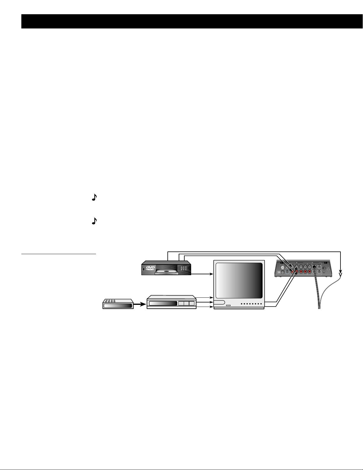
How to set up your home theater
There are two basic methods for setting up your home theater. It is best to connect components directly to the Lifestyle® 50 multi-room interface, and select the sound source using the
Personal™ music center. A second option is to use a stereo TV as the switching center to
select the sound source. In each example, the analog outputs from the DVD player or other
digital device are connected to the AUX inputs. You may need extra long audio cables or
extensions for some of these connections.
Preferred method: Connect video sound sources directly to the Lifestyle® 50
system (Figure 12)
You may connect up to three video sound sources directly to your Lifestyle® 50 system. For
example, connect the analog outputs of your DVD player to AUX, the VCR fixed outputs to
VIDEO 1, and the TV to VIDEO 2 on the back of the multi-room interface. Connect the coaxial
digital audio output from your DVD player to the female RCA coaxial connector on the audio
input cable (connecting the multi-room interface with the module) using a male-to-male RCA
audio cable.
If a valid digital signal is received by the Lifestyle® 50 system through the audio input cable,
the system plays that audio source. If no valid digital signal is received, the system selects
the analog audio signal sent to AUX.
When connecting your TV:
• Connect the TV fixed audio outputs to the VIDEO 2 inputs on the multi-room interface.
• Turn the TV speakers off or the volume all the way down. (If there is an internal/external
speakers switch, select external speakers. Do not connect any speakers to the TV.)
• Turn off any special TV settings such as expanded stereo, mega-bass, phantom or
SAP. They prevent proper surround sound processing through your Lifestyle® system.
• Set the TV balance control to the center of the dial or range.
• Set tone controls to flat or the middle position (neutral).
• Set TV to the stereo position.
Figure 12
Preferred home theater connections to the Lifestyle
®
50 system
Cable TV
DVD player
VCR
L
R
V
Multi-room
interface
L
R
V
Digital audio output
AUDIO INPUT AUDIO INPUT
AUX VIDEO 1 VIDEO 2 TAPE IN OUT
ANTENNA
LLLLL
FM AM
RRRRR
BOSE CD
RECORD
ROOM A
(PRIMARY)
ROOM B
POWER
!
SEE USER’S
GUIDE
12V AC
1.6A
SERIAL
DATA
ROOM DROOM C
To the module
V
L
R
TV
AM189854_05_V.PDF October 17, 2001 13
Page 16
Setting Up
Alternate method: Connect video sound sources to your TV (Figure 13)
If your stereo TV has fixed audio outputs (audio outputs that do not change when you adjust
the TV volume) and it allows you to select the source of the signal (VCR, laserdisc, cable,
etc.), then you can:
• Connect your DVD player L and R outputs to the AUX inputs of the multi-room interface.
• Connect the DVD video output to one of the video inputs on the TV.
• Connect the coaxial digital audio output from your DVD player to the female RCA
connection on the audio input cable (connecting the multi-room interface with the
module) using a male-to-male RCA cable.
• Connect the TV fixed audio outputs to the VIDEO 1 inputs of the multi-room interface.
• Turn the TV speakers off or the volume all the way down. (If there is an internal/external
speakers switch, select external speakers. Do not connect any speakers to the TV.)
• Turn off any special TV settings such as expanded stereo, mega-bass, phantom or
SAP. They prevent proper surround processing through your Lifestyle® system.
• Set the TV balance control to the center of the dial or range.
• Set tone controls to flat or the middle position (neutral).
• Set TV to the stereo position.
Note:
If necessary, as a second choice, you can use the variable audio outputs from your
stereo TV. Turn off or disconnect the TV’s speakers and leave the volume control up – close to
the maximum setting.
Note:
If you connect your stereo VCR through your stereo TV, do not use coaxial cable.
Instead, connect the VCR L and R audio outputs to the TV L and R audio inputs to ensure
proper stereo and surround sound.
Figure 13
Alternate home theater connections to the Lifestyle® 50 system
Cable TV
DVD player
VCR
Digital audio output
R
L
V
Multi-room interface
AUDIO INPUT AUDIO INPUT
AUX VIDEO 1 VIDEO 2 TAPE IN OUT
ANTENNA
LLLLL
FM AM
RRRRR
BOSE CD
RECORD
ROOM A
(PRIMARY)
ROOM B
POWER
!
SEE USER’S
GUIDE
12V AC
1.6A
SERIAL
DATA
ROOM DROOM C
TV
L
R
V
L
R
To the Acoustimass
module
14 October 17, 2001 AM189854_05_V.PDF
Page 17

About the video source
Your TV is the display for the video (picture) signal. Thus, the video signal must be connected
directly to the TV. Do not connect it to the Lifestyle® 50 system.
Note:
For assistance with video connections between your DVD player and/or VCR and TV,
see your video components manuals.
Note:
There is no video signal input (usually a yellow-coded jack) on the multi-room interface. The VIDEO INPUT jacks are for audio from a video source.
Connecting other external components
Use standard RCA audio cables to connect other components to your Lifestyle® system’s
multi-room interface, matching the red connector to R (right) and white (or black) connector
to L (left).
You can use a Y-adapter (available at electronics stores) to connect a mono source.
Tape deck
To use an external tape recorder (analog audio cassette, analog open reel, digital audio tape,
or Digital Compact Cassette), connect the inputs (REC) of the tape deck to the interface
RECORD OUT jacks. Connect the outputs (PLAY) from the tape deck to the interface TAPE IN
jacks. See Figure 14.
Setting Up
Figure 14
Connecting external components
Laserdisc player or additional CD changer
To use one of these components, connect its audio outputs to the multi-room interface
VIDEO 1, VIDEO 2, or AUX (if not used for a digital source) input jacks, matching the red plug
to R (right) and black or white plug to L (left). See Figure 14.
Turntable
To connect a turntable, you need a phono preamplifier (with RIAA equalization). You can order
the appropriate model (PN 252603) from Bose® Customer Service (See the inside back cover
for locations and phone numbers.). Connect the audio outputs of the phono preamplifier to
the interface VIDEO 1, VIDEO 2, or AUX (if not used for a digital source) input jacks, matching
the red plug to R (right) and black or white plug to L (left).
Note:
The Lifestyle® 50 system cannot turn on or off a connected component.
DVD player, other
digital source, or
other device
ANTENNA
FM AM
BOSE CD
AUDIO INPUT AUDIO OUTPUT
AUX VIDEO 1 VIDEO 2 TAPE IN OUT
LLLLL
RRRRR
VCR, TV,
or laserdisc
RECORD
ROOM A
(PRIMARY)
VCR, TV,
or laserdisc
ROOM B
ROOM DROOM C
POWER
SEE USER’S
GUIDE
12V AC
SERIAL
DATA
Outputs Inputs
!
1.6A
Tape deck
AM189854_05_V.PDF October 17, 2001 15
Page 18

Setting Up
Connecting the antennas
The rear panel of your multi-room interface provides connections for the supplied AM and FM
antennas (Figure 15). Untie and straighten the bundled wires on each antenna. Antennas
provide better reception when their wires are fully extended.
Figure 15
The antenna connections
Figure 16
The FM dipole antenna and
AM loop antenna
Coaxial (75Ω)
FM antenna jack
AM antenna
jack
FM antenna connections
1. Plug the FM antenna connector into the FM ANTENNA jack on the back of the interface.
2. Spread out the antenna arms. Experiment with both the placement and the angle of this
antenna to provide optimum FM reception.
Note:
connections. To install an outdoor antenna, consult a qualified installer. Follow all safety
instructions.
A central antenna or cable, or an outdoor FM antenna, may be used with the antenna
AM antenna connections
Note:
1. Plug the AM antenna microplug into the AM ANTENNA jack on the interface.
2. Stand the loop antenna on the base, following the instructions enclosed with the antenna.
3. Move the loop part of the antenna as far away from the multi-room interface as possible,
To install the AM antenna on a wall, follow the instructions enclosed with the antenna.
but at least 20 inches (50 cm) away, and at least 4 feet (1.2 m) from the Acoustimass
module. Experiment with the orientation of the loop for optimum AM reception.
Connecting to a cable radio signal
To connect your system to the FM signal available from some cable TV companies, contact
your cable provider for assistance. The connection is made to the FM 75Ω EXTERNAL
antenna connector on the back of the interface.
CAUTION:
not the cable TV band, is transmitted to the system. It is necessary to use a splitter that filters
the signal to prevent any re-emissions of the TV spectrum through the system.
Be certain that the installation includes a signal splitter so that only the FM band,
16 October 17, 2001 AM189854_05_V.PDF
Page 19

Connecting power to your system
Plug the Acoustimass® module power cord into an AC power (mains) outlet. Then plug in the
multi-room interface power pack.
Note:
Your speakers will not operate unless you complete all cable and power connections
before turning on the system.
CAUTION:
Be sure the three shipping screws on the bottom of the CD changer have been
removed before turning on the system.
Setting up the Personal™ music center
Set up the Personal music center after the rest of the system is connected and plugged in.
Note:
with the closest multi-room interface.
1. Hold the music center within a few feet of the multi-room interface.
2. Slide open the battery compartment on the back of the music center (Figure 17).
3. Insert 4 AAA or IEC-R03 1.5V batteries, or the equivalent, as shown. Match the + and –
4. Slide the battery compartment cover back into place.
5. Turn the music center over and touch the screen to wake it up if it appears blank. Press
If the music center continuously displays “NO RESPONSE,” you need to try to establish
its link with the multi-room interface again. Hold the music center close to the multi-room
interface. Press and hold MUTE for about 5 seconds until you hear a beep and then release.
After about 10 seconds, the music center should beep twice to confirm that the link is
established.
When batteries are first installed in the music center, it sets up a radio-frequency link
symbols on the batteries with the + and – markings inside the compartment.
ON/OFF, FM, or any other source button to turn the system on.
Setting Up
Figure 17
Installing batteries and waking
up the display for the first time
4 AAA
batteries
Note:
Replace the batteries when the LOW BATTERY message first appears. See “Replac-
Battery compartment cover
b. Turn over and wake up displaya. Install batteries
ing batteries” on page 44. Alkaline batteries are recommended.
AM189854_05_V.PDF October 17, 2001 17
Page 20

Operating Your Lifestyle® 50 System
Turning on the system
You are ready to enjoy your new Lifestyle® system. Your Personal™ music center places
complete control of the system operations in your hands. The center is portable, communicating with the rest of the system through a two-way radio-frequency link. The display is
backlit for easy viewing, and provides visual feedback of current system operations and
available options. To allow for maximum battery life, the display and backlight turn off a short
time after your last button press. You only need to touch the screen to wake up the music
center.
• To learn more about the display, see “Using the Personal music center display” on pages
20-21.
• To operate the AM/FM radio, see “Listening to the radio” on pages 26-28.
• To operate the CD changer, see “Listening to compact discs” on pages 29-34. To verify
your system setup, listen to the instructions on the Test CD.
• To control external components, see “Using the system with external components”
on page 35.
• To use your system in multiple rooms, see “Operating in more than one room” on
pages 41-43.
Turning the system on
1. Touch the music center screen to wake up the display (Figure 18). The last display that you
used appears on the screen.
2. Press ON/OFF to turn the system on to the last source used, or press a SOURCE button
(FM, AM, CD, VIDEO 1, VIDEO 2, TAPE, AUX) to select and turn on that source (Figure 19).
Note:
Initially, the AM and FM sources turn on in 2-speaker mode (front right and front left).
All other sources initially turn on in 5-speaker mode. To change the speaker settings, see
“Selecting the number of speakers” on page 22.
Figure 18
Waking up the display
Figure 19
Turning on a source
Turning the system off
• Press the ON/OFF button.
18 October 17, 2001 AM189854_05_V.PDF
Page 21

Operating Your Lifestyle® 50 System
Adjusting the volume
• Touch the VOLUME ▲ (up) or ▼ (down) button to raise or lower the volume.
• Volume settings range from 0 to 100. Volume settings are displayed while being adjusted.
• If the volume was above 80 when the system was turned off, it will turn on at 80 (to
prevent surprising you with an extremely high volume).
Muting your system
• Press the MUTE button to silence the system. MUTE flashes on the display when the
system is muted.
• Press MUTE again or VOLUME ▲ to restore volume to the muted speakers.
Using the sleep timer
• Press the SLEEP button to access the sleep timer for automatic shutoff. The display
flashes a sleep time of 30 minutes or the most recent sleep time setting (Figure 20). The
SLEEP indicator is also flashing.
• Use the arrow buttons to set the sleep timer to 1 to 99 minutes.
• Press the START button to start the counter. The START button disappears and a CLEAR
button appears at the bottom of the display.
Figure 20
The SLEEP display
Before pressing START …
The SLEEP indicator flashes
After pressing START …
ON
OFF
SLEEP
ÂENU
Set time with arrow buttons
Press START to begin countdown
SLEEP
DONE
VOLUÂE
ÂUTE
VOLUÂE
CLEAR
The CLEAR button is shown and the START button disappears
While the sleep timer is running, you can:
• Press CLEAR to cancel the timer.
• Press DONE to exit from the SLEEP display.
• Press SLEEP again to view the time remaining.
The selected SLEEP time is remembered by the music center. The next time SLEEP is
selected, the display shows the last SLEEP time used.
AM189854_05_V.PDF October 17, 2001 19
Page 22

Operating Your Lifestyle® 50 System
Using the Personal™ music center display
The music center display provides information on the system functions. The display offers
different combinations of buttons to provide control of the function you are using. Sometimes
an item on the display will flash to provide information about a system function. When an item
flashes faster, it is alerting you to a needed action.
Using the primary buttons
The primary buttons (ON/OFF, SLEEP, MENU, VOLUME, and MUTE) are located at the left
and right sides of the display.
Figure 21
The display showing the primary
buttons, SOURCE buttons, and
KEYPAD buttons
Primary
buttons
SOURCE
buttons
Current status
display
Source display
area
KEYPAD
buttons
Primary
buttons
Using the SOURCE buttons
The seven source buttons provide direct access to the three built-in sources (FM, AM, CD)
and up to four external components connected to the system. The Lifestyle® system can
select an external component and adjust the volume, but it cannot turn a connected component on or off.
Use the SOURCE button to show or hide the source buttons.
Using the KEYPAD buttons
The numeric buttons provide direct access to commonly used features of the three built-in
sources (FM, AM, CD). The or arrow symbol to the left or right of the KEYPAD button
indicates whether you are using the keypad for presets or tuning (in FM or AM mode), or
selecting disc or track (in CD mode).
Use the KEYPAD button to show or hide the keypad buttons and select PRESET or TUNE, or
DISC or TRACK.
Using the current status display
The center of the screen displays information about the current status of the system. The top
of the status area indicates which source is selected or if the power is off. The next three lines
let you set tuner or CD functions, using the or arrow buttons to adjust the settings. The
center area also includes indication of CD modes such as RANDOM and REPEA T, or if the
SLEEP function is on.
20 October 17, 2001 AM189854_05_V.PDF
Page 23

Operating Your Lifestyle® 50 System
Using the MENU items
The menu items are selected by pressing the MENU button to step through the list until the
function you want is displayed. Menu items are available in the list if they are applicable to the
current state of the system. You can exit from any menu item by pressing DONE or ON/OFF
or pressing MENU until you return to the main screen.
Figure 22
Selecting MENU items – one at
a time
KEYPAD
ON
OFF
SLEEP
ÂENU
PRESETS
CD OPTIONS
SPEAKERS
WIPE SCREEN
RECORD OUT
SIGNAL LEVELS
STEREO
SEEK
PRESET
DONE
VOLUÂE
ÂUTE
VOLUÂE
STORE
MENU items display area
PRESETS
You can preset a maximum of 25 FM and 25 AM radio stations. In addition to using the
PRESETS menu, you can set presets directly from the KEYPAD buttons. See pages 27-28.
WIPE SCREEN
Select this option when you need to wipe the display to clean off fingerprints, etc. WIPE
SCREEN allows you 20 seconds to clean the display without affecting the system operations.
See “Cleaning the Personal™ music center” on page 45.
CD OPTIONS
Select this option to create and edit a CD play list even if you are listening to another source.
If you are in CD mode, you can also select random and repeat play. See “Using the CD
OPTIONS menu” on pages 32-34.
SPEAKERS
Use this option to select the number of speakers you want to listen to, and adjust surround
and center speaker volume levels. See “Selecting the number of speakers” on page 22.
RECORD OUT
Use this option to select which source is directed to the RECORD OUT (line out) jacks,
allowing you to listen to one source while recording another. See “Using a tape recorder with
your system” on page 35.
SIGNAL LEVELS
The SIGNAL LEVELS option allows you to read the received signal strength of AM and FM
radio stations. It also allows you to equalize the volume levels of externally connected
components. See “Optimizing AM/FM radio reception” on page 36, or “Equalizing the volume
levels of external sources” on page 37.
AM189854_05_V.PDF October 17, 2001 21
Page 24

Operating Your Lifestyle® 50 System
Listening to the system
Your Lifestyle® 50 system uses digital signal processing to bring even greater realism and
impact to both movies and music recordings. Built-in Dolby Digital decoding delivers up to
5.1 discrete audio channels (that is, five for the independent Jewel Cube® speakers and one
for rich bass from the Acoustimass® module) from DVD, digital TV, next-generation cable
boxes, and satellite receivers. With analog formats, as well as for two-channel PCM and
Dolby Digital bitstreams, Videostage® decoding steers front information to the left, center, and
right, and directs surround information to the left and right rear channels. As a result, the
sound of stereo broadcasts and rented or recorded tapes can approach that of your DVD
discs.
In addition, Videostage decoding can process a one-channel program and direct five-channel
sound to five independent speakers. Dialogue remains locked on-screen, while music and
ambient effects fill the room to increase your listening enjoyment.
You may choose to listen through two, three, or five speakers. Traditional stereo may be
enjoyed through two or more speakers. Listening through three or five speakers helps anchor
the dialogue of movies to the picture and provides a more solid image for music vocals. For
the greatest surround effect, listening through five speakers gives you the most convincing
sound experience.
Selecting the number of speakers
Initially, the AM and FM sources turn on in 2-speaker mode (front right and front left). All other
sources initially turn on in 5-speaker mode. To change the speakers setting, press the MENU
button until SPEAKERS is displayed (Figure 23). Use the or arrow buttons to change
speaker mode from 5 to 3 or 2. Speaker settings are remembered for source and room.
Figure 23
Speaker selection display
Adjusting center and surround levels
The SPEAKERS selection display (Figure 23) also allows you to adjust the volume levels of
the center and surround speakers. At the factory, these levels are set to zero. To adjust them,
press the MENU button until SPEAKERS is displayed. Then use the or arrow buttons to
adjust the levels.
• The CENTER level can be adjusted to soften or emphasize center speaker image.
• The SURROUND level can be adjusted to move the surround information forward in the
room or further to the rear.
The system remembers the center and surround level settings for the room in which they
were adjusted.
22 October 17, 2001 AM189854_05_V.PDF
Page 25

Figure 24
Selecting enhanced mode
(FILM BASS) for movie
soundtracks
Operating Your Lifestyle® 50 System
Using enhanced mode for movie soundtracks
Pressing VIDEO 1 or VIDEO 2 initially turns the system on in enhanced mode, with bass and
treble settings specially designed for proper playback of movie soundtracks. Enhanced mode
is turned on or off using the FILM BASS button on the display (Figure 24). When enhanced
mode is on, the words FILM BASS appear on the display. Pressing TAPE initially turns the
system on in the standard listening mode. FILM BASS cannot be engaged for AM, FM or CD.
Note:
Enhanced mode provides more bass and less treble, as is specified for proper
playback of movie soundtracks.
Using simulated surround for mono movie material
Bose® Videostage® decoding can process a one-channel program into five-speaker sound,
directing the signals so that dialogue remains locked on-screen, while music and ambient
effects fill the room. You experience a surround sensation, providing extra enjoyment when
you watch older, pre-stereo movies. This feature can be used for mono TV, FM, and AM
programs. It is automatically turned on when a Dolby Digital bitstream indicates that it
contains a mono program.
For other mono program sources, you can engage or disengage this feature using the
Personal™ music center. Press MENU and hold it until drc or 1ch:5 appears on the display. If
drc is displayed, press either of the top or arrow buttons to select 1ch:5 (Figure 25).
Then use the lower or arrow buttons to select between On or – – (Off). Initially, this
feature is On for AM and off ( – – ) for all other sources. If you change the setting for any
source, the system is reset to these settings when you turn off a room.
Figure 25
Selecting five-speaker sound for
a mono source
AM189854_05_V.PDF October 17, 2001 23
Page 26

Operating Your Lifestyle® 50 System
Digital Dynamic Range® compression
This feature automatically monitors and adjusts the volume to let you hear soft sounds
(particularly dialogue), but reduces the chance of you being overwhelmed by a loud special
effect such as an explosion. Digital Dynamic Range compression is initially disengaged for all
sound sources.
You can engage or disengage Digital Dynamic Range compression using the Personal music
center. Press MENU and hold it for about two seconds. You should see drc on the display. If
not, press the left or right arrow button until drc is displayed. Using the left or right arrow
button below drc, select On or – – (Off) (Figure 26). The music center remembers your
settings in the event of a power loss.
Figure 26
Selecting Digital Dynamic
Range compression
Listening to digital sound
Turning on the digital audio source
Turn on the DVD player, DTV, or other digital audio source. Make sure a disc is loaded in the
DVD player.
Turning on the system and choosing digital sound
Press AUX to turn your system on to play digital sound. If your Lifestyle® system does not
receive a valid PCM or Dolby Digital bitstream, it will automatically select the analog signal
connected to the AUX jacks on the multi-room interface.
Selecting listening material
To select material with compatible digital-audio bitstreams, look for the terms PCM or Dolby
Digital, or the symbol
MPEG-2 or DTS digital bitstreams. Make sure a connection is made between your DVD
player or Digital TV’s digital audio output and your system’s digital audio input.
To select surround-encoded analog or digital audio material, look for the terms Surround or
Dolby Surround, the symbol 3 on tapes and discs, or the word “surround” preced-
ing a TV broadcast. You can listen to any program material in five-speaker (surround sound)
mode, though you may not hear sound from all five speakers all the time. Some monaural and
stereo materials will not cause sound to be directed to the surround speakers. Even with
surround-encoded material there are times when no sounds are directed to the surround
speakers.
1
on DVD-Video discs. Your Lifestyle® 50 system cannot process
24 October 17, 2001 AM189854_05_V.PDF
Page 27

Operating the special features
See “Listening to the system” on pages 22-24 for a more detailed explanation of these
special features.
Enhanced mode
When you select The mode is To change this
VIDEO 1, VIDEO 2 Enhanced (FILM BASS on) Press the FILM BASS button.
TAPE, AUX Standard (FILM BASS off) Press the FILM BASS button.
CD, AM or FM Standard Not applicable. You cannot
Simulated surround (monaural into 5 speakers)
When your audio source is Simulated surround is To change this
AUX source with Mono Dolby ON Press and hold the MENU
Digital, AM button. Select 1ch:5 and
Anything else OFF Press and hold the MENU
Operating Your Lifestyle® 50 System
select enhanced mode for CD,
AM or FM.
switch to – – (Off).
button. Select 1ch:5 and
switch to On.
Digital Dynamic Range® compression
When you select Digital Dynamic Range is To change this
Any SOURCE OFF Press and hold the MENU
button. Select drc and switch
to On.
AM189854_05_V.PDF October 17, 2001 25
Page 28

Operating Your Lifestyle® 50 System
Listening to the radio
Your Lifestyle® system has a built-in AM/FM radio. Good AM/FM radio reception depends on
the location and orientation of the AM and FM antennas. See “FM antenna connections” and
“AM antenna connections” on page 16 for proper antenna installation. See “Optimizing AM/
FM radio reception” on page 36 for help with antenna adjustment.
Turning the system on and choosing the radio
Press FM or AM to turn your system on to the most recently selected FM or AM station. If the
system is already on, use the FM or AM button to select either of these sources.
Setting radio channel spacing
On some multi-room interfaces, the AM and FM channel spacing can be set for North
America (US: 10 kHz for AM and 200 kHz for FM) or Europe (EU: 9 kHz for AM and 50 kHz for
FM). Select the channel spacing most appropriate for your area.
To change between US and EU channel spacing, press and hold the SOURCE button for two
seconds. Press either arrow button until tunr appears. Using the arrow buttons select US or
EU. Press DONE to exit.
Selecting FM or AM
Press the FM or AM SOURCE button to turn on the radio band desired. Select a station by
tuning manually, seeking a strong station, or selecting a preset station.
Figure 27
Tuning the radio from the FM
source display
Manually tuning a radio station
To manually tune a radio station, press the (decrease) or (increase) arrow button on
either side of the frequency display to change the frequency in small steps (Figure 27). Or,
press the KEYPAD button until the indicator arrow points toward TUNE. Then use the
number buttons to enter the frequency of the station you want to tune. The left-most digit is
entered first and the display flashes while you enter more digits. When you have entered the
station frequency, the system selects that station or the closest valid station.
To tune a station, use up/down arrow keys, or
point the KEYPAD to TUNE and enter numbers.
Receiving FM stereo or monaural broadcasts
When receiving sufficiently strong FM stereo broadcast signals, the radio automatically
receives in the stereo mode; the STEREO indicator appears on the display. Weak stereo
signals are received in the monoaural mode (the STEREO indicator is off).
To force the tuner to receive in stereo mode only, press and hold the center of the station
display until you hear a high-pitched beep. To receive in monaural mode only, press and hold
until you hear a low-pitched beep. However, even though you may have forced the stereo
mode, monaural broadcast material is still heard in monaural. Retuning the station cancels
any forcing.
26 October 17, 2001 AM189854_05_V.PDF
Page 29

Operating Your Lifestyle® 50 System
Receiving AM stations
Normally, the AM radio receives sufficiently strong AM stations using a wide bandwidth filter.
If you experience difficulty tuning to a weak AM station, you can force the AM tuner to use a
narrow bandwidth filter to eliminate interference from other stations.
To force the tuner to use a narrow bandwidth filter, press and hold the center of the station
display until you hear a low-pitched beep. To switch back to the wide bandwidth filter, press
and hold until you hear a high-pitched beep. Retuning the station cancels any forcing.
Seeking the strongest stations
Press either the or SEEK arrow button to tune to the next strong station.
Selecting a preset station
You can select a preset station using the or PRESET arrow buttons or the KEYPAD.
To use the KEYPAD, press the KEYPAD button until the indicator arrow points toward
PRESET. Then enter the number of the preset station you want.
Note:
If you have not selected a valid preset location, the system remains at the current
setting.
Setting a station preset
Your Lifestyle® system can store up to 25 FM and 25 AM station presets. You can set presets
using the STORE button, KEYPAD, preset number display area, or PRESETS menu.
Figure 28
Setting presets using the
PRESET number display or
KEYPAD
Setting a preset using the STORE button
During normal AM/FM radio operation when the keypad is not displayed, you can see the
STORE button at the bottom of the screen. To store a preset in the next available location,
press and hold the STORE button until the music center beeps and the new preset number
appears.
Using the KEYPAD to quick-store presets
You can quick-store presets in locations 1 through 9. Hold down any KEYPAD number button
from 1 to 9 until the music center beeps and the new preset number appears.
Setting a preset using the preset number display
You can quick-store a station using the PRESET number display. Press and hold down the
display area between the PRESET arrow buttons (dashes or a preset number are displayed)
until the system beeps. After the beep, the new preset number is shown. This stores a new
preset at the next available preset number. Use the PRESETS menu (page 28) if you want to
change a preset to a different station.
Note:
If the display says FULL after pressing the PRESET number display area, no more
presets are available. See “Erasing a preset station” on page 28.
Press and hold here to store a preset,
or to quick-store a preset, press
and hold any button 1 through 9
AM189854_05_V.PDF October 17, 2001 27
Page 30

Operating Your Lifestyle® 50 System
Setting presets using the PRESETS menu
You can set station presets using the PRESETS menu which is available only when AM or FM
is the selected source.
To set a preset station:
1. Select the AM or FM source.
2. Press the MENU button once to access the PRESETS menu (Figure 29).
3. Select an unused preset number and then a station using the arrow buttons. Stations can
also be selected using SEEK or the KEYPAD. Any preset number not used flashes on the
display.
4. Press the STORE button to set the selected station to a selected preset number. To
confirm a stored preset, the music center displays the station frequency and a CLEAR
button (Figure 30). The CLEAR button appears whenever you select a stored preset, giving
you the option of erasing the setting.
Figure 29
Selecting a station for a preset
Figure 30
After setting a station as
preset 3
Erasing a preset station
To erase a preset station, press MENU once to access the PRESETS menu. Select the preset
number you want to erase and press CLEAR.
Managing your preset stations
Using the PRESETS menu makes it easier to organize your preset stations, and store a
specific station in a specific preset location. Here are some tips:
• Since any station can be assigned to more than one preset number, you can reserve a
group of preset numbers for each household member to allow for different preferences.
• You can reserve different number groups for different types of stations.
• For easy reference, you may want to keep a written record of your presets.
28 October 17, 2001 AM189854_05_V.PDF
Page 31

6
6
5
5
4
4
3
3
2
2
1
1
Listening to compact discs
Using the CD changer
You can load the CD changer with up to six compact discs at a time.
Loading discs into the CD magazine
To load the CD magazine, hold it as shown in Figure 31. Insert up to six discs, label side
up. Take care to place only one disc in each slot. Note the slot numbers 1 through 6, from
bottom to top, on the front edge window. These numbers correspond to the CD numbers
on the display.
CAUTION:
could cause them to become stuck, and could damage the discs, the CD magazine, or the
CD changer.
Note:
Figure 31
Loading and ejecting a CD
If a disc is upside-down, it does not play. The display flashes the disc number.
Operating Your Lifestyle® 50 System
Do not insert more than one disc into any slot. Forcing two discs into one slot
Figure 32
Loading and unloading the CD
magazine
6
6
5
5
4
4
3
3
2
2
1
1
6
D
I
S
K
M
A
G
A
Z
I
N
E
Ejecting discs from the CD magazine
Press the white lever that corresponds to the disc you want to eject. This ejects the disc far
enough for you to grasp the edge and remove it from the magazine (Figure 31).
Loading the CD magazine into the CD changer
Open the CD changer door. Insert the CD magazine fully into the CD changer, following the
direction of the arrow on the magazine (Figure 32).
Ejecting the CD magazine from the CD changer
Press the EJECT button, at the lower left of the magazine slot, to remove the magazine
(Figure 32). If a CD is playing, pressing the EJECT button stops the CD, replaces it in the
magazine, and ejects the magazine.
6
6
5
5
4
4
3
3
2
2
6 DISK MAGAZINE
1
1
6
6
E
5
5
IN
Z
A
4
G
4
A
M
K
3
3
S
I
D
6
2
2
1
1
Eject button
AM189854_05_V.PDF October 17, 2001 29
Page 32

Operating Your Lifestyle® 50 System
ÂENU
SLEEP
ON
OFF
VOLUÂE
VOLUÂE
ÂUTE
SOURCE
DISC
TRACK
PLAY PAUSE STOP
PLAY
LIST
KEYPAD
OÂIT
TRACK
Turning the system on and choosing the CD changer
Press the CD source button to select the CD changer. If the system is off, this turns it on at
the same time. When you press CD, the CD changer display (Figure 33) appears on the
display. If a CD has been loaded, it begins to play. If no disc is installed, a noCd message is
displayed.
Note:
To prevent excessive wear on the CD mechanism, CD play or random play operations
automatically stop after 24 hours.
Figure 33
The CD changer display
Skip DISC or
TRACK
backward
Scan CD
backward
Elapsed play time
for current track
Scan CD
forward
Skip DISC
or TRACK
forward
PLA Y, PAUSE, STOP
and PLA Y LIST buttons
Press and hold here to store a
TRACK number in the CD play list
Removes TRACK
number from normal play
To play a CD
Press the PLAY button. The button symbol flashes until play begins.
To pause a CD
Press the PAUSE button. The button symbol flashes. Press PAUSE or PLAY to resume.
If left unattended, the CD changer mode changes from PAUSE to STOP after 20 minutes. You
can skip tracks forward or backward while paused.
To stop a CD
Press the STOP ■ or OFF button. If you press STOP ■, the disc number, total play time and
number of tracks appear briefly on the display.
To skip to other tracks
To skip to the next track, press the TRACK forward button. To skip to the previous track,
press the TRACK backward button. Pressing TRACK while playing a CD skips you to
the beginning of the track in play.
To play another disc
Press the DISC forward or backward button. This skips you to the next or previous disc
in the changer and starts playing the CD. The message CHANGING is displayed until play
begins. Empty disc changer slots are automatically skipped.
30 October 17, 2001 AM189854_05_V.PDF
Page 33

Operating Your Lifestyle® 50 System
To scan a disc
Press and hold the scan forward or backward button (these are the ones to the left
and right of the play time display). Scanning back or forward stops at the first or last track of
the disc. You can scan a CD while it is paused.
To add a track to the play list
Skip to the track you want to add to the play list. Press and hold the TRACK number display
area. The current track number is stored in the next available location in the CD play list.
To omit a track from normal play
Select the TRACK number, then press and hold the OMIT TRACK button. You can omit up to
15 tracks and you can omit a track while it is playing. Omitted tracks are not played during
normal, repeat, or random play modes.
You can skip to an omitted track using the TRACK forward or backward button.
When on an omitted track, the word OMITTED is displayed and the OMIT TRACK button
becomes CLEAR OMIT TRACK.
To clear an omitted track and restore it to normal play, skip to the omitted track number and
then press CLEAR OMIT TRACK. To clear all omitted tracks at the same time, eject the CD
magazine.
To listen to the CD play list
• Press the PLAY LIST button (Figure 34).
• To cancel PLAY LIST, press STOP, or press PLAY LIST again. If you press STOP, the
current CD stops playing. If you press PLAY LIST again, the current CD continues to play.
Note:
The PLAY LIST button appears only after you store CD selections in the play list
memory. To program a play list, see “Programming a CD play list” on page 33.
If the play list has an invalid entry, such as a track number that can’t be found, it is skipped
during play. If a CD was removed or exchanged, the system tries to play the disc as programmed. Unavailable items are skipped.
Figure 34
Display after pressing
PLAY LIST
ON
OFF
SLEEP
ÂENU
SOURCE
PLAY
LIST
PLAY PAUSE STOP
DISC
TRACK
LIST
VOLUÂE
ÂUTE
VOLUÂE
AM189854_05_V.PDF October 17, 2001 31
Page 34

Operating Your Lifestyle® 50 System
Using the CD OPTIONS menu
From the CD OPTIONS menu you can select repeat or random play, or program a CD play
list. To access the CD OPTIONS, press the MENU button until CD OPTIONS is displayed
(Figure 35). You can do this while a CD plays if you wish.
Figure 35
CD options display
ON
OFF
SLEEP
ÂENU
CD OPTIONS
EDIT
PLAY
LIST
DISC
TRACK
REPEAT
RANDOÂ
DISC
DISCTRACK
ALL
DONE
ALL
OFF
VOLUÂE
ÂUTE
VOLUÂE
Press to program
a CD play list
Press for random
or repeat modes
Selecting repeat and random modes
Repeat and random modes remain active until you press STOP ■ or OFF. To place the
system in a repeat or random mode, go to the MENU button and select CD OPTIONS. Use
the REPEAT and RANDOM buttons to select the mode you want. Press DONE to exit the CD
OPTIONS menu. To cancel a repeat or random mode, press OFF in the CD OPTIONS menu.
You can select the following repeat and random modes:
Mode Press What it does
Repeat track REPEAT TRACK Repeats selected track for 24 hrs.
Repeat CD REPEAT DISC Plays all tracks on selected disc in order.
Repeats for 24 hrs.
Repeat all REPEAT ALL Plays all loaded discs in order. Repeats for
24 hrs.
Random CD RANDOM DISC Plays selected disc once in random order
and stops.
Random all RANDOM ALL Plays all tracks on all discs once in
random order and stops.
Repeat random CD REPEAT DISC then RANDOM DISC Plays selected disc in random order.
Repeats for 24 hrs.
Repeat random all REPEAT ALL then RANDOM ALL Plays all discs and tracks in random order.
Repeats for 24 hrs.
Selecting play list modes
You can also apply repeat or random modes to your CD play list. Press the PLAY LIST button
before pressing the MENU button to select the CD OPTIONS menu. Then select one of the
following play list modes using the REPEAT and RANDOM buttons. When you are through,
press DONE to exit.
Play list mode Press What it does
Random list RANDOM DISC or RANDOM ALL Plays all selections in the PLAY LIST
Repeat list REPEAT DISC or REPEAT ALL Repeats PLAY LIST.
Repeat track list REPEAT TRACK Repeats selected PLAY LIST item.
Repeat random list REPEAT DISC or REPEAT ALL Plays and repeats all selections in the
then RANDOM DISC or RANDOM ALL PLAY LIST in random order.
once in random order.
Note:
If you select random and repeat modes that cannot be combined (REPEAT TRACK
and RANDOM DISC, for example), the system accepts the most recently entered choice.
32 October 17, 2001 AM189854_05_V.PDF
Page 35

Operating Your Lifestyle® 50 System
Programming a CD play list
Using the Lifestyle® system’s programming feature, you can create your own CD play list of
up to 50 tracks (including repeats) from the loaded discs. You can create or edit a CD play list
even while listening to another source. However, you can’t edit the play list while the list is
playing. To create or edit a CD play list, press the MENU button and select CD OPTIONS.
Note:
at a time.
To create a CD play list
1. Press EDIT PLAY LIST. The next available item number is flashing to indicate that the
2. Select a DISC and TRACK number using the or arrow buttons.
3. Press STORE to enter the CD selection into memory under the selected ITEM number. The
4. Press the ITEM right arrow for the next item number.
5. Repeat steps 2, 3 and 4 to add more items to the list. When the list has 50 programmed
6. When you have completed your play list, press DONE to exit.
If you have more than one Personal™ music center, only one user can edit the play list
music center is ready for programming (Figure 36).
ITEM number stops flashing.
items, the STORE button disappears.
Figure 36
Starting to build the CD play list
ON
OFF
SLEEP
CD OPTIONS
ÂENU
Next available location flashes
ITEÂ
DISC
TRACK
Press to store selected DISC and TRACK
DONE
VOLUÂE
ÂUTE
VOLUÂE
STORE
To change an entry in the CD play list
1. Press EDIT PLAY LIST. If the list has 50 items stored, the ITEM field indicates FULL and
does not flash.
2. Select the number of the item you want to change and press CLEAR.
3. Select a new DISC and TRACK and press STORE.
4. To make other changes, repeat steps 2 and 3. Otherwise, press DONE to exit.
AM189854_05_V.PDF October 17, 2001 33
Page 36

Operating Your Lifestyle® 50 System
To insert a new track in an existing play list
1. Press EDIT PLAY LIST. If the ITEM field indicates FULL, you can’t insert a new item unless
you delete one or more items from the list.
2. Select the ITEM number of the location where you want to insert a new CD selection. The
ITEM number should not be flashing.
3. Press INSERT (Figure 37). The ITEM number begins flashing to indicate that the item
you were viewing was moved up one item number leaving your selected ITEM number
available.
4. Select a DISC and TRACK number and press STORE.
To delete a track from the play list
1. Press EDIT PLAY LIST.
2. Select the number of the item you want to delete and press CLEAR (Figure 37). The
TRACK and DISC numbers change to dashes. The location is cleared and all items after
this one are moved down one item number.
3. To delete other items, repeat step 2. Otherwise, press DONE to exit.
Figure 37
CLEAR LIST and CLEAR
buttons available on the display
after first selection is entered
ON
OFF
SLEEP
ÂENU
CD OPTIONS
ITEÂ
DISC
TRACK
CLEAR
LIST
CLEAR INSERT
DONE
VOLUÂE
ÂUTE
VOLUÂE
Press to remove
item from list
To erase the entire CD play list
1. From the CD OPTIONS menu, press CLEAR LIST.
2. Press YES to confirm.
Press to remove
entire list
Press to insert
item into list
34 October 17, 2001 AM189854_05_V.PDF
Page 37

Operating Your Lifestyle® 50 System
Using the system with external components
Follow the instructions on pages 12-15 for connecting components.
Turn on your component directly or by using its remote control. Press VOLUME ▲ or ▼ on
your Personal™ music center to raise or lower the volume. Control all other functions at the
source, referring to its owner’s manual if necessary. To begin, make sure the component is
turned on and a tape, CD, DVD, laserdisc, etc. is loaded. If an external component sounds
significantly louder or softer than other sources, see “Equalizing the volume levels of external
sources” on page 37.
Note:
The Lifestyle® 50 system cannot turn a connected component on or off.
Turning the system on and selecting the component
Press VIDEO 1, VIDEO 2, AUX, or TAPE on your Personal music center to select the desired
component. This turns your system on and selects the component connected to that input. If
the system is already on, this button selects the component.
The appropriate display indicator appears when the system is on and the component is
selected.
CAUTION:
your video tapes, audio tapes, and other magnetic media. However, you should not store
tapes directly on or near the Acoustimass module.
The magnetic field from the Acoustimass® module is not an immediate risk to
Figure 38
The RECORD OUT menu
display
Using a tape recorder with your system
If you are listening to any source except TAPE, the output signal of that source is directed to
the RECORD OUT jacks.
Note:
D. In a multi-room system, the source that is playing in the room designated by the letter
closest to the begining of the alphabet is sent to the RECORD OUT jacks.
You may also specify a source to be directed to the RECORD OUT jacks even if you are not
listening to that source. To do this:
1. Select RECORD OUT with the MENU button. The words RECORD OUT are displayed
2. Select a source to record. The selected source appears in the source display area in place
3. When you are ready, set the tape deck to record.
The ROOM outputs of the Lifestyle® 50 system are designated by the letters A through
under the source display area (Figure 38).
of the dashes (Figure 38). If you want to remove your RECORD OUT selection, press
CLEAR. The dashes reappear.
The selected source stays on until you turn RECORD OUT off. If the CD changer is
selected for RECORD OUT, it shuts off after 24 hours if you have not turned it off sooner.
AM189854_05_V.PDF October 17, 2001 35
Page 38

Operating Your Lifestyle® 50 System
Fine-tuning your system
In most situations, you only need to follow the speaker placement guidelines (see “Setting
Up” on pages 6-8) for your system to provide excellent sound quality. You do not need to
adjust tone settings for changes in volume, since Bose® patented integrated signal process-
Figure 39
Treble and bass controls
ing provides a natural tonal balance over the full range of volume settings.
If desired, you can further fine-tune your system as described here.
Adjusting speaker controls
The Lifestyle® 50 system treble and bass controls are located on the Acoustimass® module
(Figure 39). They allow you to adjust the treble (high frequencies) and bass (low frequencies).
In the normal setting, the dots on each control are in the 12 o’clock position. You can also
locate the normal setting by feeling when the control settles into the notch at this position.
Turn the controls clockwise to increase, and counterclockwise to decrease, the amount of
treble or bass.
®
Compensating for room acoustics
The acoustics (sound qualities) of your room can affect the overall sound quality of any
speaker system. In general, you can reduce many problems with acoustics by the careful use
of the treble and bass controls.
Treble
Bass
Too much or too little treble
Rooms that reflect a lot of sound, especially those with bare floors and walls, may sound
overly shrill or “bright.” Turning down the treble control (toward – ) decreases treble sound.
Rooms with a lot of sound-absorbing furnishings, such as upholstered furniture, wall-to-wall
carpet, or heavy drapes, may sound muffled or dull. Moving speakers further away from soft
furnishings increases treble. You can increase treble sound by slightly turning up the treble
control (toward + ).
Too much or too little bass
You can decrease bass sound by turning down the bass control (toward – ). To increase bass,
turn up the bass control (toward + ). Acoustimass module placement also affects the amount
of bass you hear. Placing the module closer to the corner of the room increases bass. Moving
the module away from the corner decreases bass.
Optimizing AM/FM radio reception
You can adjust the orientation of your AM/FM antenna for the strongest signal by selecting
SIGNAL LEVELS with the MENU button (Figure 40). Select the AM or FM radio, and the
display shows you the strength level of the received signal. While watching the display,
reposition your antenna until the highest possible signal level is achieved. The signal level can
vary from 0 to 99. The manual tuning keys are provided so that you can check the signal
strengths of multiple stations.
Figure 40
AM/FM antenna signal strength
display
36 October 17, 2001 AM189854_05_V.PDF
Page 39

Figure 41
Gain adjustment display
Operating Your Lifestyle® 50 System
Equalizing the volume levels of external sources
The SIGNAL LEVELS selection in the MENU options allows you to adjust and equalize the
volume gain levels received from externally connected sources (VIDEO 1, VIDEO 2, AUX, TAPE).
For example, you can adjust the gain level of an external source so that volume level 50 on this
source sounds as loud as level 50 from a built-in source.
1. Using the MENU button, select SIGNAL LEVELS.
2. Press VIDEO 1, VIDEO 2, TAPE or AUX and you are shown a gain adjustment display
(Figure 41). After listening to the built-in sources (FM, AM, CD) at your preferred volume
level, use the arrow keys to adjust the signal level settings (GAIN) of the connected
sources until you get the same volumes. The adjustment range is from –15 to +15.
Figure 42
LCD contrast adjustment
display
Figure 43
Beep adjustment display
Adjusting LCD contrast
You can adjust the contrast of the display. Press and hold the SOURCE button until Lcd
appears. Use the lower arrow buttons to change the contrast level.
Adjusting the Personal™ music center beep
You can adjust the loudness of the beep made when pressing the display buttons. Press and
hold the SOURCE button until Lcd appears. Use the upper arrow buttons to select the bEEP
display. Use the arrow buttons to select between Lo, HI, and – – (off).
AM189854_05_V.PDF October 17, 2001 37
Page 40

Operating Your Lifestyle® 50 System
Forcing the SOURCE buttons to stay on
Normally, the SOURCE buttons are automatically removed from the display following certain
operations. You can change the behavior of these buttons so that they remain in the state you
last set them (on or off screen) using the SOURCE button.
1. Press and hold the SOURCE button until Lcd appears.
2. Press either upper arrow key until you see STAY and the SOURCE button appears in the
upper left region of the display (Figure 44).
3. Press either lower arrow key to select (Yes).
4. To return the SOURCE buttons to normal operation, select
(No).
Figure 44
Selecting the display mode of
the SOURCE buttons
ON
OFF
SLEEP
ÂENU
SOURCE
DONE
VOLUÂE
ÂUTE
VOLUÂE
= SOURCE buttons are removed following certain operations.
Press SOURCE to access them again.
= SOURCE buttons remain as you last set them with the
SOURCE button, except for when the system is off.
Forcing the KEYPAD buttons to stay on
Normally, the numerical keypad buttons are automatically removed from the display following
certain operations. You can change the behavior of these buttons so that they remain in the
state you last set them (on or off screen) using the KEYPAD button.
1. Press and hold the SOURCE button until Lcd appears.
2. Press either upper arrow key until you see STAY and the KEYPAD button appears in the
upper right region of the display (Figure 45).
3. Press either lower arrow key to select (Yes).
4. To return the KEYPAD to normal operation, select (No).
Figure 45
Selecting the display mode of
the KEYPAD buttons
ON
OFF
SLEEP
ÂENU
KEYPAD
DONE
VOLUÂE
ÂUTE
VOLUÂE
= KEYPAD buttons are removed following certain operations.
Press KEYPAD to access them again.
= KEYPAD buttons remain as you last set them with the
KEYPAD button.
38 October 17, 2001 AM189854_05_V.PDF
Page 41

Figure 46
Fade control display
Operating Your Lifestyle® 50 System
Adjusting the display fade time
The fade control display allows you to adjust the length of time the music center display stays
on (after your last button press) before it fades. To adjust this time:
1. Press and hold the SOURCE button until Lcd appears.
2. Press either upper arrow key until you see FAdE on the display (Figure 46).
3. Press either lower arrow key to select a number between –15 and +15 (initial setting = 0).
This is the number of seconds that is added or subtracted from the display fade time. A
positive number keeps the display on longer than the initial setting. A negative number
allows the display to fade sooner than the initital setting.
4. Press DONE to exit this mode.
AM189854_05_V.PDF October 17, 2001 39
Page 42

Operating a Multi-Room Lifestyle® 50 System
Connecting additional rooms
Follow the placement guidelines for the Bose® powered speakers that you plan to connect.
Then review your plan for how to connect these speakers to the multi-room interface in your
primary room. If you have questions or need extension cables to complete the connections,
call Bose Customer Service at the numbers listed on the back inside cover of this owner’s
guide.
CAUTION:
begin hooking up additional speakers.
Connect the audio input cable from your additional powered speakers to the selected ROOM
jack on the back of the multi-room interface.
1. Plug the small black multi-pin connector (flat side facing up) into the jack marked
ROOM B, C, or D on the back of the interface.
2. Follow the instructions that came with your speakers for connecting the cable to the
speakers.
Note:
Figure 47
ROOM jacks on the multi-room
interface
Make sure all components are unplugged from the power outlet before you
Be sure that each connector is inserted completely into each jack.
Room A, B, C, and D jacks
40 October 17, 2001 AM189854_05_V.pdf
Page 43

Operating in more than one room
Your Lifestyle® 50 system can control up to four sets of Bose® powered speakers, allowing
your family to enjoy different audio sources (CD, radio, TV, etc.) in up to four rooms. These
rooms are referred to as room A, B, C, and D, with room A being the primary room (the one
used for a one-room system). If two or more rooms are connected to your system, the
Personal™ music center displays ROOM and HOUSE buttons, and room indicators (A, B, C,
and/or D). Figure 48 shows an example display for a two-room system.
Operating a Multi-Room Lifestyle® 50 System
Figure 48
Example display for a two-room
system
The ROOM button lets you control a single room or two or more rooms that share a source
The HOUSE button lets you control all connected rooms as one
The room indicators tell you what was selected by the
ROOM or HOUSE button
Understanding the room indicators
A boxed letter indicates the presently-selected room or rooms. The selected room is
affected by any source changes, or any change you make using the VOLUME, MUTE,
ON/OFF, or SLEEP buttons.
B An unboxed letter indicates a room listening to a shared source. A shared source is one
that is playing in the controlled room as well as in up to three additional rooms. If you
change the radio station, CD track, etc., of the shared source, the change affects all
rooms sharing this source. However, you cannot change sources for all affected rooms
at the same time. The VOLUME, MUTE, ON/OFF, and SLEEP buttons only affect the
boxed room(s).
An empty box appears for each connected room when you press the HOUSE button.
When you change the volume in the HOUSE mode, the numerical level appearing on the
display does not represent the actual volume level in all connected rooms. It only
represents the actual volume in rooms represented by a boxed letter.
AM189854_05_V.pdf October 17, 2001 41
Page 44

Operating a Multi-Room Lifestyle® 50 System
Using the ROOM button
The ROOM button allows you to select any connected room and control any sound source
you want to hear in that room. Each time you press the ROOM button you can transfer
control from one room to the next in A-B-C-D order. The room indicators on the display tell
you what is currently selected. Rooms listening to a shared source can be linked and controlled as one room.
Turning on different sources in more than one room
Let’s say you have a two-room system (rooms A and B) and the entire system is off. To turn
on a different source in each room:
1. Wake up the Personal™ music center.
2. Press the ROOM button until the room indicator
such as VIDEO 1, to turn on the system and listen to your DVD player in room A. Adjust
the volume to the desired level.
3. Press the ROOM button again. The room indicator
button, such as CD, to listen to a CD in room B. Again, adjust the volume to the desired
level.
4. Press the ROOM button again and notice that the room indicator is displayed. You are
controlling room A once again and the displays indicates that the VIDEO 1 source is on.
is displayed. Press a source button,
is displayed. Press a different source
Setting up a shared source
Now, let’s say the system is already on and you want to play the FM radio in rooms A and B:
1. Wake up the Personal music center.
2. Press the ROOM button until the room indicator is displayed. Press the FM source
button and adjust the volume to the desired level for room A.
3. Press the ROOM button again to select room . Press the FM source button and adjust
A
the volume to the desired level for room B. Now, the indicators
B
4. Press the ROOM button again. The indicators
you can control these two rooms together. Any button command given now (SOURCE,
VOLUME, MUTE, ON/OFF, SLEEP) is applied to both rooms.
Note:
Remember that there are limits to using different sources in different rooms. With one
A
appear on the display indicating that
B
are displayed.
tuner, the system cannot play one radio station in one room and another radio station in
another. Similarly, with one CD changer, the system cannot play two different CDs at the same
time.
Linking rooms for common control
There are two ways to link rooms in order to control them as one.
• Set up a shared source in two or more rooms and select them together using the ROOM
button. See “Setting up a shared source” above.
• Link all connected rooms using the HOUSE button. See “Using the HOUSE button” on
page 43.
Returning to single-room control
After you have gained control of multiple rooms using the ROOM button, you can use the
ROOM button again to gain control of a single room. Press ROOM until the room you want is
displayed ( , , , or ). Control that room as desired.
42 October 17, 2001 AM189854_05_V.pdf
Page 45

Operating a Multi-Room Lifestyle® 50 System
Using the HOUSE button
Using the HOUSE button, you can link all rooms together and control them as one. When you
press the HOUSE button, an empty box indicator is displayed for each connected room. Any
button pressed after that (any source button, VOLUME, MUTE, or SLEEP) affects every room.
When you are done listening you can press OFF to turn off the entire system.
Note:
again cancels HOUSE mode.
Press the HOUSE button before each command to apply that command to all rooms:
Press … To do this …
HOUSE then a source Play the selected source in all connected rooms.
HOUSE then VOLUME ▲/▼ Adjust the volume up or down by the same amount in all
HOUSE then MUTE Silence all connected rooms that are on, even if any were
HOUSE then SLEEP Set the SLEEP timer for all rooms that are on. The SLEEP time
HOUSE then OFF Turn off the entire system.
Note:
for individual rooms by using the ROOM button to select each room and setting SLEEP.
When two or more rooms are linked, adjusting the SLEEP time affects all linked rooms
(indicated by boxed letters).
If you do not press any additional buttons after pressing HOUSE, pressing HOUSE
rooms that are on, or all connected rooms if they are all off.
The system remembers the differences among the original
room volume settings.
previously muted individually. To cancel this command, press
HOUSE then MUTE again. Any rooms that were muted before
this command was given stay silent until individually unmuted.
If you unmute an individual room after it was muted by a
HOUSE - MUTE command, the other rooms remain silent until
each one is unmuted individually. Pressing HOUSE then
VOLUME ▲ unmutes all muted rooms.
selected applies to all rooms that are on even if they are
playing different sources. If the SLEEP timer was already set
in one or more rooms, the display shows the longest time
already set. You can accept this time or change it for all the
rooms. To cancel the HOUSE - SLEEP command, press
HOUSE, SLEEP, CLEAR, and then DONE.
Instead of setting the whole house to one sleep time, you can set different sleep times
Using more than one Personal™ music center
If you have a multi-room system, you can add additional music centers for some or all of the
connected rooms. Each multi-room interface can be controlled by a maximum of four music
centers. Each music center can control up to four rooms.
To add a new music center to your system, follow the setup instructions on page 17. Be sure
to install the batteries and turn it on for the first time close to the multi-room interface to allow
the new music center to set up a radio frequency link with your system. If the multi-room
interface is not plugged in or the music center is out of range, the display indicates NO
RESPONSE.
AM189854_05_V.pdf October 17, 2001 43
Page 46

Maintaining Your Lifestyle® 50 System
Finding a misplaced Personal™ music center
The “find me” feature assists you in locating the music center. Press the LOCATE MUSIC
CENTER button on the back of the multi-room interface (under the antenna connections, next
to the CD changer cable connection). The volume drops in any rooms that are on and any
music center within range of the multi-room interface eventually begins beeping and flashing.
The beeping and flashing continues for two minutes. Touching the screen of any music center
stops it from beeping and flashing. Pressing VOLUME ▲ on any music center cancels the
LOCATE MUSIC CENTER function.
Figure 49
The LOCATE MUSIC CENTER
button
LOCATE MUSIC CENTER button
Replacing batteries
The LOW BATTERY message appears when batteries are nearly depleted. As batteries get
weaker, the message flashes faster and display timeouts become shorter.
Figure 50
The LOW BATTERY warning
message
System settings are not lost when batteries are changed or battery power fails.
Replace the batteries with 4 AAA or IEC-R03 1.5V alkaline batteries, matching the + and –
symbols on the batteries with the + and – markings inside the compartment and on the back
label. See “Setting up the Personal™ music center” on page 17 for battery installation
instructions.
ON
OFF
SLEEP
ÂENU
LOW BATTERY
VOLUÂE
ÂUTE
VOLUÂE
44 October 17, 2001 AM189854_05_V.pdf
Page 47

Cleaning the system
The only maintenance your system may need is periodic cleaning and replacing the music
center batteries. For information on replacing the batteries see page 17.
CAUTION:
chemicals, or cleaning solutions containing alcohol, ammonia, or abrasives.
CAUTION:
get into any system component, turn the system off and allow it to air dry. Then turn it on
again. If you notice any problems with its functioning, turn it off and contact Bose® Customer
Service.
Cleaning the Personal™ music center
You can use an ammonia-free window cleaner on a soft cloth to clean the music center
including the display screen. See the cautions at the top of the page.
Before you start cleaning the display, press the MENU button until you select WIPE SCREEN.
You can use this option to disable the display buttons for up to 20 seconds while you wipe
the screen. When you are ready to wipe the screen, press START to begin the countdown.
This enables you to clean the screen without affecting system operation. The system beeps
during the last five seconds to warn you that time is running out.
Figure 51
Entering the WIPE SCREEN
display
Maintaining Your Lifestyle® 50 System
Do not use any spray cleaners near the system. Do not use any solvents,
Do not allow liquids to spill into any openings of the system. If liquids accidently
Cleaning the CD changer
Use only a soft cloth to clean the outside of the CD changer. See the cautions at the top of
the page.
Cleaning the speakers and Acoustimass® module
Clean the surface of your speakers with a soft, damp cloth. You can use an ammonia-free
window cleaner on a soft cloth to maintain the finish. See the cautions at the top of the page.
The speaker grille panels require no special care, although you may vacuum them carefully
with a soft-bristled attachment, if necessary.
AM189854_05_V.pdf October 17, 2001 45
Page 48

Maintaining Your Lifestyle® 50 System
Troubleshooting
Problem What to do
System does not function • Make sure the power connector is inserted securely into the multi-room interface, the power
at all cord is inserted securely into the Acoustimass® module, the power pack and power cord
are plugged fully into operating AC wall outlets.
• Be sure to select a source (CD, AM/FM, etc.).
• Unplug the multi-room interface power pack for a few seconds, then reconnect it. This
allows the unit to reset itself after a power surge or power interruption.
No sound • Increase the volume.
• Check to see if MUTE is flashing on the display. If it is, press the MUTE button to unmute
the sound.
• Make sure the audio input cable is firmly seated in the multi-room interface ROOM A jack
and the multi-pin connector on the other end is firmly seated in the Acoustimass module
AUDIO INPUT jack.
• Check speaker connections.
• Make sure the digital audio input cable is firmly seated in the multi-room interface AUX jack
and the other end of the cable is firmly seated in the connector at the digital source.
• Check the connections for any external components. Make sure to select the correct
source for the desired input.
• Be sure the CD is placed correctly label-side up in the magazine, and the magazine is
inserted properly in the CD changer.
• Connect the FM and AM antennas.
No sound from • Make sure the center cube cable is connected at both ends.
center speaker • Check the settings in the SPEAKERS menu.
Too much sound • Adjust the CENTER level in the SPEAKERS menu.
from center speaker
No sound from • Select 5 speakers in the SPEAKERS menu.
surround speakers • Adjust the SURROUND level in the SPEAKERS menu.
• Make sure the video sound source is stereo and surround-encoded, and the component
used (TV, VCR, DVD, or laserdisc player) is stereo.
Surround speakers • Adjust the SURROUND level in the SPEAKERS menu.
are too loud • Make sure that the left and right front speakers are connected to the front speaker jacks
(blue) and the left and right surround speakers are connected to the surround speaker
jacks (orange). Use the supplied test CD.
Music center control is • Check batteries and their polarity (+ and –). See page 17.
inconsistent, shows a • Operate the music center closer to the multi-room interface.
NO RESPONSE message, • Move the music center a few feet to avoid any area of interference.
or does not work • Make sure the audio input cable is firmly seated, and uncoiled.
• Make sure the multi-room interface is connected and plugged in.
• If NO RESPONSE is continuously displayed, the link between your music center and the
multi-room interface may be broken. To re-establish the link, hold the center close to the
interface. Press and hold MUTE for about 5 seconds until you hear a second beep. After
about 10 seconds, you should hear two beeps to confirm that the link is established.
Note:
The music center establishes a link with the closest multi-room interface.
46 October 17, 2001 AM189854_05_V.pdf
Page 49

Maintaining Your Lifestyle® 50 System
Problem What to do
CD does not play • Check to see if the PLAY button symbol in the display is flashing.
• Make sure the magazine is properly inserted.
• Check to see if there is a disc in the magazine, label-side up. Display shows a flashing
number for a disc that is label-side down or cannot be read. Display shows noCd if no
discs are loaded.
• Eject the magazine and try loading the CD again.
• There may be dirt or dust on the CD. Clean the CD.
• The disc may be defective. Try another disc.
• The CD changer cannot play a DVD disc.
• If the CD changer is not properly connected the display shows Plug in cd.
• A display message Err indicates a mechanical error. Call Bose® Customer Service (see
inside back cover for listings).
Radio does not work • Make sure antennas are connected properly.
• Position the AM antenna as far away from the multi-room interface as possible, at least 20
inches away.
• Adjust antenna position to improve reception. Use SIGNAL LEVELS menu to determine
best reception. You may be in an area of weak signal coverage.
• Make sure the AM antenna is upright.
• Move antennas farther from TV or other electronic equipment.
FM sound is distorted • Adjust antenna position to reduce interference.
Sound is distorted • Make sure speaker cables are not damaged and the connections are secure.
• Reduce the output level from any external components connected to the CD changer.
No tape, CD, VCR, • Check the connections.
or TV sound • Make sure the component is turned on.
• Refer to the component owner’s manual.
A display button does not • Calibrate the display screen. When you can only initiate a function by pressing the button
activate its function when too far off center, then a display screen calibration may be necessary. Calibrating the
pressed on center display screen aligns the button icon with the appropriate area of the screen.
1. Press and hold the source display area (top center) until CAL appears.
2. Press the SOURCE button as close to its center as possible. The KEYPAD button
appears.
3. Press the KEYPAD button as close to its center as possible. A small round button
appears at the bottom right of the screen.
4. Press the small round button as close to its center as possible to exit the calibration
function with a newly calibrated screen.
• Contact Customer Service for assistance.
Warranty period
The Bose® Lifestyle® 50 system is covered by a limited 1-year transferable warranty. Details of
the warranty are provided on the warranty card that came with your system. Please fill out the
information section on the card and mail it to Bose.
Customer Service
For additional help in solving problems, contact Bose Customer Service. See the inside back
cover for Bose Customer Service offices and phone numbers.
AM189854_05_V.pdf October 17, 2001 47
Page 50

Technical information
Product Information
Speaker system power rating
USA/Canada: 120V~ 50/60 Hz 350W
Europe/Australia: 220-240V~ 50/60 Hz 350W
Dual voltage: 115/230V~ 50/60 Hz 350W
Multi-room interface
power pack power rating
USA/Canada: 120V~ 60 Hz 25VA
Europe: 230V~ 50 Hz 25VA
Australia: 240V~ 50 Hz 25VA
Dual voltage: 120V~ 60 Hz 25VA and
230V~ 50 Hz 25VA
Multi-room interface inputs
TAPE IN: 2Vrms, maximum
AUX, VIDEO 1, VIDEO 2: 2Vrms, maximum
FM antenna: 75Ω
AM antenna: 12µH
Power: 12V~, 1.0A
Multi-room interface outputs
RECORD OUT: fixed audio
ROOM A, B, C, D: auto-adjusting fixed or
variable audio
SERIAL DATA: for future use
ROOM connector pinouts:
1: left audio
2: right audio
3: left audio
4: right audio
5: audio ground
6: +10V control line
7: SMART SPEAKER data
8: control line ground
876
543
21
Personal™ music center
Power: 6V DC (1.5V x 4 AAA)
Range: 65 feet (20 m)
Dimensions
Personal music center
8.8" W x 4.1" D x 1.4" H
(22.4 cm x 10.5 cm x 3.6 cm)
Multi-room interface
7.4" W x 4.0" D x 2.1" H
(18.8 cm x 10.0 cm x 5.5 cm)
CD changer
15.5" W x 8.0" D x 2.6" H
(39.4 cm x 20.3 cm x 6.6 cm)
Jewel Cube® speaker
2.2" W x 3.2" D x 4.4" H
(5.6 cm x 8.1 cm x 11.2 cm)
Acoustimass® module
23.3" W x 7.5" D x 14.0" H
(59.0 cm x 19.0 cm x 35.5 cm)
Weights
Personal music center
.8 lb (.4 kg)
Multi-room interface
.8 lb (.4 kg)
CD changer
5.9 lb (2.7 kg)
Jewel Cube speaker
1 lb (0.5 kg)
Acoustimass module
33 lb (15.0 kg)
Total shipping weight
62 lb (28.2 kg)
Finish
Personal music center
Polymer, painted
Multi-room interface
Polymer
CD changer
Aluminum
Jewel Cube speakers
Polymer, painted
Acoustimass module
Vinyl veneer, Polymer
Accessories
To find out about mounting brackets, stands, CD magazines, and connecting additional
Bose® powered loudspeakers, contact your Bose dealer. Or call Bose directly (see inside
back cover for phone numbers).
48 October 17, 2001 AM189854_05_V.pdf
Page 51

Index
A
Acoustimass® module
best bass performance 8
connecting 10
location 8
magnetic field 8
power cord 5, 17
rubber feet 5, 8
treble and bass controls 36
ventilation 8
Additional powered speakers 40
Additional rooms
connecting 40
operating 41–43
AM 18, 20, 26–27, 28
AM/FM radio
antenna 5
antenna connections 16
antenna placement 16
channel spacing 26
reception 36
select 18
station preset 27, 28
TUNE 26
ANTENNA SIGNAL 36
AUDIO INPUT
external components 15
jacks 15
AUDIO OUTPUT
additional rooms 40
connections 40
PRIMARY 10
AUX 12–15, 18
B
Bass control 36
Batteries
first installed 17
LOW BATTERY 44
replacing 17, 44
Beep adjustment display 37
Built-in sources 20
C
CAUTION marks 2
CD 18, 20, 29, 30–32, 33–34
CD changer
display 30
loading 29
location 8
omit a track 31
PAUSE 30
PLAY 30
select 30
shipping screws 5, 17
STOP 30
TRACK 30
CD magazine
ejecting 29
ejecting discs 29
loading 29
CD modes
play list 32
repeat and random 32
CD OPTIONS 21, 32
display 32
menu 32
PLAY LIST 33, 34
programming 33
repeat or random play 32
CD play list
CLEAR, CLEAR LIST 34
EDIT 33, 34
erase 34
FULL 34
INSERT 34
ITEM 33
programming 33
STORE 33, 34
CENTER 22
CHANGING 30
Cleaning
Acoustimass module 45
CD changer 45
personal music center 45
speakers 45
WIPE SCREEN 21, 45
CLEAR, CLEAR LIST 34
CLEAR OMIT TRACK 31
Connecting powered speakers 40
Customer Service 47
D
Digital Dynamic Range® compression
24, 25
Digital signal processing 4, 22
Digital sound 4, 24
DISC
scan 31
skip 30
display contrast 37
DONE
CD OPTIONS 32
EDIT PLAY LIST 34
SLEEP 19
WIPE SCREEN 45
E
EDIT PLAY LIST 33, 34
Ejecting
CD magazine 29
discs 29
Err 47
External components
connecting 12–15
selecting 35
volume gain levels 37
External tape deck
inputs/outputs 15
recording 35
F
FILM BASS 23
FM 18, 20, 26–27, 28
FULL 34
G
GAIN
adjustment 37
volume levels 37
H
Home theater setup 12–15
HOUSE
button 41
indicator 43
I
INSERT 34
ITEM 33, 34
J
Jewel Cube® speakers
cleaning 45
connecting 9
locations 6, 7
K
KEYPAD
presets or tuning 20
show or hide 20, 38
L
LCD contrast 37
Loading the CD magazine 29
LOCATE MUSIC CENTER 44
Locations
Acoustimass module 8
CD changer 8
Jewel Cube speakers 6, 7
multi-room interface 8
LOW BATTERY 17, 44
M
Magnetic field 6, 8
MENU
CD OPTIONS 32
items 21
PRESETS 28
primary button 20
RECORD OUT 35
AM189854_05_V.pdf October 17, 2001 49
Page 52

Index
SIGNAL LEVELS 36, 37
Multi-room interface
inputs/outputs 48
location 8
power pack 5, 11
rear panel connections 12–15, 16
MUTE 20, 42, 43
N
NO RESPONSE 17, 43, 46
noCd 30, 47
O
OMIT TRACK 31
OMITTED 31
ON/OFF 17, 18, 20
P
PAUSE 30
Personal™ music center
batteries 17
battery compartment 17
display 17, 18, 20
finding a misplaced 44
MENU items 21
primary buttons 20
radio-frequency link 17, 46
range 48
set up 17
waking up 17, 18
PLAY 30
PLAY LIST 33, 34
change an entry 33
CLEAR LIST 34
create 33
delete a track 34
erase 34
insert a new track 34
ITEM 33, 34
Plug in cd 47
Power rating
power pack 48
speaker system 48
PRESETS
maximum 21
menu 27, 28
number display 27
selecting 27
setting 27, 28
Primary buttons 20
R
Radio channel spacing 26
Radio-frequency link 17, 46
RANDOM 32
RECORD OUT
display 35
jacks 35
option 21
source 35
REPEAT 32
ROOM
button 41, 42
jacks 10, 40, 48
S
Safety information 2
SEEK 27
Serial numbers 3, 5
Shared source 41–43
SIGNAL LEVELS 21, 36
Signal splitter 16
Simulated surround sound 23, 24, 25
SLEEP 19, 20, 41–43
SOURCE 20, 42
SPEAKERS 21, 22
Speakers
additional 40
cleaning 45
connecting 9
placement 6, 7
powered 40
selecting the number of 22
START
SLEEP 19
WIPE SCREEN 45
Station presets
erasing 28
managing 28
maximum 21
number 27
PRESETS menu 21, 27, 28
quick-store 27
selecting 27
setting 27, 28
STOP 30
STORE
CD play list 33, 34
preset 27, 28
SURROUND 22
System
accessories 48
additional cables 8
connecting 9–11
control 18
current status display 20
dimensions 48
fine-tuning 36
finish 48
muting 19, 41–43
ON/OFF 18, 19, 41–43
parts 5
serial numbers 3, 5
troubleshooting 46, 47
turning on or off 18, 19, 41–43
unpacking 5
VOLUME 19, 41–43
weights 48
System cables
audio input 5, 8, 10, 12–15
CD changer 5, 8, 10
extension wire 9
speaker cables 5, 6, 7, 9
to lengthen 8, 9
T
TAPE 18, 35
Technical information 48
TRACK 30–32, 34
Treble control 36
Troubleshooting 46, 47
TUNE 26
Tuning
manually 26
selecting a preset 27
strongest stations 27, 36
tunr 26
U
Unlinking rooms 42
Unpacking 5
V
VIDEO 1 12–15, 18
VIDEO 2 12–15, 18
Video sound
center and surround levels 22
digital 4, 12, 22, 24
Digital Dynamic Range® compression
24, 25
enhanced mode (FILM BASS) 23, 25
mono movie material 4, 22–24
setting up 12–15
Videostage® decoding 4, 22, 23
VOLUME
adjusting 19, 41–43
equalizing 37
primary buttons 20
W
Warranty 47
WIPE SCREEN 21, 45
50 October 17, 2001 AM189854_05_V.pdf
Page 53

Index
AM189854_05_V.pdf October 17, 2001 51
Page 54

USA
Bose Corporation, The Mountain
Framingham, MA 01701-9168
1-800-367-4008
Phone hours - ET (eastern time):
Weekdays 8:30 a.m. to 8 p.m.
Saturdays 9 a.m. to 3 p.m.
Canada
Bose Ltd., 1-35 East Beaver Creek Road
Richmond Hill, Ontario L4B 1B3
1-800-465-2673
Phone hours - ET (eastern time):
Weekdays 9 a.m. to 5 p.m.
European Office
Bose Products B.V., Nijverheidstraat 8
1135 GE Edam, Nederland
TEL 0299-390111 FAX 0299-390114
Australia
Bose Pty Limited, 1 Sorrell Street
Parramatta NSW, 2150
TEL 02 9204-6111 FAX 02 9204-6122
Belgique/België
Bose N.V., Limesweg 2, B-3700 Tongeren
TEL 012-390800 FAX 012-390840
Danmark
Bose A/S, Industrivej 7, 2605 Brøndby
TEL 4343-7777 FAX 4343-7818
Italia
Bose S.p.A., Via della Magliana 876
00148 Roma
www.bose.iT
TEL 06-65670802 FAX 06-65680167
Japan
Bose K.K., Shibuya YT Building
28-3 Maruyama-cho
Shibuya-ku, Tokyo 150
TEL 3-5489-0955 FAX 3-5489-0592
Nederland
Bose B.V., Nijverheidstraat 8
1135 GE Edam
TEL 0299-390111 FAX 0299-390109
Norge
Bose A/S, Solheimsgate 11
N-2001, Lillestrøm
TEL 63-817380 FAX 63-810819
Österreich
Bose Ges.m.b.H., Vienna Business Park
Wienerbergstrasse 7 (10.OG)
A-1100 Vienna
TEL 01-60404340 FAX 01-604043423
Schweiz
Bose AG, Rünenbergerstrasse 13
4460-Gelterkinden
TEL 061-9815544 FAX 061-9815502
Deutschland
Bose GmbH, Max-Planck-Straße 36d
D-61381 Friedrichsdorf
TEL 06172-71040 FAX 06172-710419
France
Bose S.A., 6, rue Saint Vincent
78100 Saint Germain en Laye
TEL 01-30616363 FAX 01-30614105
India
Bose Corporation India Private Limited
W-16, Greater Kailash-II
New Delhi 110 048
TEL (011) 648 4462 FAX (011) 648 4463
Ireland
Bose Corporation
Carrickmacross, Co Monaghan
TEL (042) 9661988 FAX (042) 9661998
Sverige
Bose A/S, Johannefredsgatan 4
S-43153 Mölndal
TEL 31-878850 FAX 31-274891
United Kingdom
Bose Limited
1 Ambley Green
Gillingham Business Park
Gillingham, Kent ME8 ONJ
TEL 0870-741-4500 FAX 0870-741-4545
From other locations
Bose Customer Service, 1 New York Ave.
Framingham, MA 01701-9168 USA
TEL (508) 766-1900 FAX (508) 766-1919
World Wide Web
www.bose.com
Page 55

©2001 Bose Corporation
The Mountain, Framingham, MA 01701-9168 USA
189854 AM Rev. 05 JN20413
 Loading...