

Page 1
3•2•1GS Series II
3•2•1 Series II
DVD HOME ENTERTAINMENT SYSTEMS
2ZQHU¶V*XLGH
Page 2
SAFETY INFORMATION
Please read this owner’s guide
Please take the time to follow this owner’s guide carefully. It will help you set up and operate your system properly,
and enjoy all of its advanced features. Save your owner’s guide for future reference.
DanskItalianoSvenska DeutschNederlands EnglishFrançais Español
WARNING:
WARNING:
To reduce the risk of fire or electric shock, do not expose the system to rain or moisture.
This apparatus shall not be exposed to dripping or splashing, and objects filled with liquids, such as vases,
shall not be placed on the apparatus. As with any electronic products, use care not to spill liquids in any part of the system. Liquids can cause a failure and/or a fire hazard.
The CAUTION marks shown here are located on the bottom of your 3•2•1 Series II home entertainment system
media center and the rear panel of the Acoustimass module:
The lightning flash with arrowhead symbol, within an equilateral triangle, alerts the user to the presence of
uninsulated dangerous voltage within the system enclosure that may be of sufficient magnitude to constitute a risk of electric shock.
The exclamation point within an equilateral triangle alerts the user to the presence of important operating
and maintenance instructions in this owner’s guide.
CAUTION:
CAUTION:
To prevent electric shock, match wide blade of plug to wide slot, insert fully.
No naked flame sources, such as lighted candles, should be placed on the apparatus.
Class 1 laser product
This CD player is classified as a CLASS 1 LASER PRODUCT according to
EN 60825-1:1994+A1+A2, IEC60825-1:1993+A1+A2.
CAUTION:
Use of controls or adjustments or performance of procedures other than those specified herein may result
CLASS 1 LASER PRODUCT
KLASSE 1 LASER PRODUKT
LUOKAN 1 LASER LAITE
KLASS 1 LASER APPARAT
in hazardous radiation exposure. The DVD player should not be adjusted or repaired by anyone except properly qualified
service personnel.
Class B emissions limits
This Class B digital apparatus meets all requirements of the Canadian Interference-Causing Equipment Regulations.
Batteries
Please dispose of used batteries properly, following any local regulations. Do not incinerate.
This product conforms to the EMC Directive 89/336/EEC and to the Low Voltage Directive 73/23/EEC.
The complete Declaration of Conformity can be found on www.bose.com.
Additional safety information
See the additional instructions on the
Important Safety Information
sheet enclosed in the shipping carton.
2
Page 3

Dansk Italiano SvenskaDeutsch NederlandsEnglish FrançaisEspañol
CONTENTS
I
NTRODUCTION
SYSTEM SETUP
SYSTEM CONTROLS AND INDICATORS
OPERATION
CHANGING SOURCE SETTINGS
CHANGING SYSTEM OPTIONS
5
8
26
35
40
45
MAINTAINING YOUR SYSTEM
TROUBLESHOOTING
INTRODUCTION 5
Before you begin . . . . . . . . . . . . . . . . . . . . . . . . . . . . . . . . . . . . . . . . . . . . . . . . . . . . . . . . . . . . . . . . . . . . . . . . . . . . . 5
System features . . . . . . . . . . . . . . . . . . . . . . . . . . . . . . . . . . . . . . . . . . . . . . . . . . . . . . . . . . . . . . . . . . . . . . . . . . . . . . 5
Selecting compatible discs . . . . . . . . . . . . . . . . . . . . . . . . . . . . . . . . . . . . . . . . . . . . . . . . . . . . . . . . . . . . . . . . . . . . . 5
Checking for region code compatibility . . . . . . . . . . . . . . . . . . . . . . . . . . . . . . . . . . . . . . . . . . . . . . . . . . . . . . . . . . . . 6
Glossary of terms . . . . . . . . . . . . . . . . . . . . . . . . . . . . . . . . . . . . . . . . . . . . . . . . . . . . . . . . . . . . . . . . . . . . . . . . . . . . . 6
Limited warranty . . . . . . . . . . . . . . . . . . . . . . . . . . . . . . . . . . . . . . . . . . . . . . . . . . . . . . . . . . . . . . . . . . . . . . . . . . . . . . 7
For your records . . . . . . . . . . . . . . . . . . . . . . . . . . . . . . . . . . . . . . . . . . . . . . . . . . . . . . . . . . . . . . . . . . . . . . . . . . . . . . 7
SYSTEM SETUP 8
Unpacking . . . . . . . . . . . . . . . . . . . . . . . . . . . . . . . . . . . . . . . . . . . . . . . . . . . . . . . . . . . . . . . . . . . . . . . . . . . . . . . . . . 8
Selecting locations for your 3•2•1 Series II system components . . . . . . . . . . . . . . . . . . . . . . . . . . . . . . . . . . . . . . . . 9
Placing the media center . . . . . . . . . . . . . . . . . . . . . . . . . . . . . . . . . . . . . . . . . . . . . . . . . . . . . . . . . . . . . . . . . . 9
Placing the speakers . . . . . . . . . . . . . . . . . . . . . . . . . . . . . . . . . . . . . . . . . . . . . . . . . . . . . . . . . . . . . . . . . . . . . 10
Placing the Acoustimass
Making system connections . . . . . . . . . . . . . . . . . . . . . . . . . . . . . . . . . . . . . . . . . . . . . . . . . . . . . . . . . . . . . . . . . . . . 12
Connecting the Acoustimass module to the media center . . . . . . . . . . . . . . . . . . . . . . . . . . . . . . . . . . . . . . . . 12
Connecting the speakers to the Acoustimass module . . . . . . . . . . . . . . . . . . . . . . . . . . . . . . . . . . . . . . . . . . . 12
Connecting the supplied antennas . . . . . . . . . . . . . . . . . . . . . . . . . . . . . . . . . . . . . . . . . . . . . . . . . . . . . . . . . . . 14
Connecting cable FM radio . . . . . . . . . . . . . . . . . . . . . . . . . . . . . . . . . . . . . . . . . . . . . . . . . . . . . . . . . . . . . . . . 14
Connecting your TV to the media center . . . . . . . . . . . . . . . . . . . . . . . . . . . . . . . . . . . . . . . . . . . . . . . . . . . . . . . . . . . 15
Making audio connections . . . . . . . . . . . . . . . . . . . . . . . . . . . . . . . . . . . . . . . . . . . . . . . . . . . . . . . . . . . . . . . . . 15
Making composite video connections . . . . . . . . . . . . . . . . . . . . . . . . . . . . . . . . . . . . . . . . . . . . . . . . . . . . . . . . 15
Connecting your TV and VCR to the media center . . . . . . . . . . . . . . . . . . . . . . . . . . . . . . . . . . . . . . . . . . . . . . . . . . . 16
If your TV has audio output jacks . . . . . . . . . . . . . . . . . . . . . . . . . . . . . . . . . . . . . . . . . . . . . . . . . . . . . . . . . . . . 16
If your TV does not have audio output jacks . . . . . . . . . . . . . . . . . . . . . . . . . . . . . . . . . . . . . . . . . . . . . . . . . . . 17
VCR considerations . . . . . . . . . . . . . . . . . . . . . . . . . . . . . . . . . . . . . . . . . . . . . . . . . . . . . . . . . . . . . . . . . . . . . . 18
Advanced setup options . . . . . . . . . . . . . . . . . . . . . . . . . . . . . . . . . . . . . . . . . . . . . . . . . . . . . . . . . . . . . . . . . . . . . . . 18
Making S-video connections (higher quality video) . . . . . . . . . . . . . . . . . . . . . . . . . . . . . . . . . . . . . . . . . . . . . . 18
Making component video connections (highest quality video) . . . . . . . . . . . . . . . . . . . . . . . . . . . . . . . . . . . . . 19
Connecting digital audio devices . . . . . . . . . . . . . . . . . . . . . . . . . . . . . . . . . . . . . . . . . . . . . . . . . . . . . . . . . . . . 20
Connecting your cable/satellite box, TV, and VCR to the media center . . . . . . . . . . . . . . . . . . . . . . . . . . . . . . 20
Connecting a game console . . . . . . . . . . . . . . . . . . . . . . . . . . . . . . . . . . . . . . . . . . . . . . . . . . . . . . . . . . . . . . . . 22
Installing the remote control batteries . . . . . . . . . . . . . . . . . . . . . . . . . . . . . . . . . . . . . . . . . . . . . . . . . . . . . . . . . . . . . 23
Connecting the power cord . . . . . . . . . . . . . . . . . . . . . . . . . . . . . . . . . . . . . . . . . . . . . . . . . . . . . . . . . . . . . . . . . . . . . 24
Checking your system setup . . . . . . . . . . . . . . . . . . . . . . . . . . . . . . . . . . . . . . . . . . . . . . . . . . . . . . . . . . . . . . . . . . . . 25
®
module . . . . . . . . . . . . . . . . . . . . . . . . . . . . . . . . . . . . . . . . . . . . . . . . . . . . . . . . . . . 11
53
55
SYSTEM CONTROLS AND INDICATORS 26
Remote control . . . . . . . . . . . . . . . . . . . . . . . . . . . . . . . . . . . . . . . . . . . . . . . . . . . . . . . . . . . . . . . . . . . . . . . . . . . . . . . 26
Setting up your remote to control other audio/video devices . . . . . . . . . . . . . . . . . . . . . . . . . . . . . . . . . . . . . . . . . . . 30
Direct entry of a device code . . . . . . . . . . . . . . . . . . . . . . . . . . . . . . . . . . . . . . . . . . . . . . . . . . . . . . . . . . . . . . . 30
Searching for a device code . . . . . . . . . . . . . . . . . . . . . . . . . . . . . . . . . . . . . . . . . . . . . . . . . . . . . . . . . . . . . . . . 31
Verifying an entered device code . . . . . . . . . . . . . . . . . . . . . . . . . . . . . . . . . . . . . . . . . . . . . . . . . . . . . . . . . . . . 33
Changing the default channel tuner assignment . . . . . . . . . . . . . . . . . . . . . . . . . . . . . . . . . . . . . . . . . . . . . . . . . . . . . 33
The media center . . . . . . . . . . . . . . . . . . . . . . . . . . . . . . . . . . . . . . . . . . . . . . . . . . . . . . . . . . . . . . . . . . . . . . . . . . . . . 34
3
Page 4

DanskItalianoSvenska DeutschNederlands EnglishFrançais Español
OPERATION 35
Turning your system on and off . . . . . . . . . . . . . . . . . . . . . . . . . . . . . . . . . . . . . . . . . . . . . . . . . . . . . . . . . . . . . . . . . . 35
Playing video DVDs . . . . . . . . . . . . . . . . . . . . . . . . . . . . . . . . . . . . . . . . . . . . . . . . . . . . . . . . . . . . . . . . . . . . . . . . . . . 35
Basic DVD operations . . . . . . . . . . . . . . . . . . . . . . . . . . . . . . . . . . . . . . . . . . . . . . . . . . . . . . . . . . . . . . . . . . . . 36
Restricting access to video DVDs . . . . . . . . . . . . . . . . . . . . . . . . . . . . . . . . . . . . . . . . . . . . . . . . . . . . . . . . . . . 36
Playing audio CDs . . . . . . . . . . . . . . . . . . . . . . . . . . . . . . . . . . . . . . . . . . . . . . . . . . . . . . . . . . . . . . . . . . . . . . . . . . . . 37
Listening to FM/AM radio . . . . . . . . . . . . . . . . . . . . . . . . . . . . . . . . . . . . . . . . . . . . . . . . . . . . . . . . . . . . . . . . . . . . . . . 38
Tuning to a station . . . . . . . . . . . . . . . . . . . . . . . . . . . . . . . . . . . . . . . . . . . . . . . . . . . . . . . . . . . . . . . . . . . . . . . 38
Storing stations as presets . . . . . . . . . . . . . . . . . . . . . . . . . . . . . . . . . . . . . . . . . . . . . . . . . . . . . . . . . . . . . . . . . 38
Erasing a preset . . . . . . . . . . . . . . . . . . . . . . . . . . . . . . . . . . . . . . . . . . . . . . . . . . . . . . . . . . . . . . . . . . . . . . . . . 39
Playing other sources . . . . . . . . . . . . . . . . . . . . . . . . . . . . . . . . . . . . . . . . . . . . . . . . . . . . . . . . . . . . . . . . . . . . . . . . . . 39
Using the sleep timer . . . . . . . . . . . . . . . . . . . . . . . . . . . . . . . . . . . . . . . . . . . . . . . . . . . . . . . . . . . . . . . . . . . . . . . . . . 39
CHANGING SOURCE SETTINGS 40
Using the settings menus . . . . . . . . . . . . . . . . . . . . . . . . . . . . . . . . . . . . . . . . . . . . . . . . . . . . . . . . . . . . . . . . . . . . . . . 40
FM/AM settings menu . . . . . . . . . . . . . . . . . . . . . . . . . . . . . . . . . . . . . . . . . . . . . . . . . . . . . . . . . . . . . . . . . . . . . . . . . 42
CD settings menu . . . . . . . . . . . . . . . . . . . . . . . . . . . . . . . . . . . . . . . . . . . . . . . . . . . . . . . . . . . . . . . . . . . . . . . . . . . . . 42
DVD settings menu . . . . . . . . . . . . . . . . . . . . . . . . . . . . . . . . . . . . . . . . . . . . . . . . . . . . . . . . . . . . . . . . . . . . . . . . . . . 43
TV, CBL•SAT, and AUX settings menu . . . . . . . . . . . . . . . . . . . . . . . . . . . . . . . . . . . . . . . . . . . . . . . . . . . . . . . . . . . . 44
CHANGING SYSTEM OPTIONS 45
Using the System menu . . . . . . . . . . . . . . . . . . . . . . . . . . . . . . . . . . . . . . . . . . . . . . . . . . . . . . . . . . . . . . . . . . . . . . . . 45
Audio options . . . . . . . . . . . . . . . . . . . . . . . . . . . . . . . . . . . . . . . . . . . . . . . . . . . . . . . . . . . . . . . . . . . . . . . . . . . . . . . . 47
Video options . . . . . . . . . . . . . . . . . . . . . . . . . . . . . . . . . . . . . . . . . . . . . . . . . . . . . . . . . . . . . . . . . . . . . . . . . . . . . . . . 48
Media center options . . . . . . . . . . . . . . . . . . . . . . . . . . . . . . . . . . . . . . . . . . . . . . . . . . . . . . . . . . . . . . . . . . . . . . . . . . 49
Remote control options . . . . . . . . . . . . . . . . . . . . . . . . . . . . . . . . . . . . . . . . . . . . . . . . . . . . . . . . . . . . . . . . . . . . . . . . 50
DVD Lock options . . . . . . . . . . . . . . . . . . . . . . . . . . . . . . . . . . . . . . . . . . . . . . . . . . . . . . . . . . . . . . . . . . . . . . . . . . . . 51
MAINTAINING YOUR SYSTEM 53
Cleaning . . . . . . . . . . . . . . . . . . . . . . . . . . . . . . . . . . . . . . . . . . . . . . . . . . . . . . . . . . . . . . . . . . . . . . . . . . . . . . . . . . . . 53
Replacing the remote control batteries . . . . . . . . . . . . . . . . . . . . . . . . . . . . . . . . . . . . . . . . . . . . . . . . . . . . . . . . . . . . 54
Accessories . . . . . . . . . . . . . . . . . . . . . . . . . . . . . . . . . . . . . . . . . . . . . . . . . . . . . . . . . . . . . . . . . . . . . . . . . . . . . . . . . 54
TROUBLESHOOTING 55
Troubleshooting table . . . . . . . . . . . . . . . . . . . . . . . . . . . . . . . . . . . . . . . . . . . . . . . . . . . . . . . . . . . . . . . . . . . . . . . . . 55
Customer service . . . . . . . . . . . . . . . . . . . . . . . . . . . . . . . . . . . . . . . . . . . . . . . . . . . . . . . . . . . . . . . . . . . . . . . . . . . . . 56
TECHNICAL INFORMATION 57
DEVICE CODES A-1
4
Page 5

Dansk Italiano SvenskaDeutsch NederlandsEnglish FrançaisEspañol
INTRODUCTION
Before you begin
Thank you for purchasing the Bose® 3•2•1 Series II or 3•2•1 GS Series II DVD home
entertainment system, which offers superb sound, elegance, and simplicity in an advanced
home audio setup. Using Bose proprietary signal processing technology, the 3•2•1 Series II
systems provide improved spaciousness from stereo recordings, and bold movie effects from
surround-encoded materials. Yet its few parts require little effort to set up, so you can enjoy
your new system’s performance right away.
The following items are included to help you set up your system:
• Quick Setup Guide
• Detailed setup instructions in the Setup section of this guide
• Setup DVD
System features
• Integrated AM/FM tuner and DVD/CD player in a small console
• Small, easy-to-place shelf speakers and an attractive hideaway Acoustimass
• Easy-to-use infrared remote control
• Media center input jacks for a TV, cable/satellite box or other component such as a DVR
Selecting compatible discs
The DVD/CD player built into the 3•2•1 series II media center can play the following types of
discs identified by their corresponding logos:
®
module
INTRODUCTION
• Video DVD
•Video CD
• DVD+R, DVD-R,
DVD+RW and
DVD-RW
•Audio CD
•CD-R and CD-R/W
• MP3 CDs, where
– All tracks were burned in a single closed session
– The disc format is ISO9660
– Each file has a “.mp3” extension and the filename contains
no other periods
• SACDs (CD-compatible content only)
5
Page 6
INTRODUCTION
Checking for region code compatibility
For a DVD player and DVD disc to be compatible, their region code numbers must match.
These numbers are allocated according to where the player and disc are sold. The 3•2•1
Series II DVD home entertainment systems have a region code which must also match the
DVD discs.
INTRODUCTION
Check the region code number on the carton of the 3•2•1 Series II DVD home entertainment
system or on the bottom of the media center that comes in the carton. Then be sure to
choose only DVD discs that show the same region number on the disc label or front cover.
For example, a Region 1 DVD disc should display the following mark:
Glossary of terms
Aspect Ratio – The shape of the rectangular picture in a TV set. It is the width of the picture
relative to the height. Our standard TV picture, in terminology used by that industry, is 4 units
wide by 3 units high, or 4:3 (read as 4 by 3) in aspect ratio. There are currently two standard
TV aspect ratios, 4:3 and 16:9.
Chapter – In DVD-Video, a division of a title. Technically called a part of title (PTT).
Component Video – A video signal split into three parts: luminance and two color signals
(marked as YPbPr). It provides the highest resolution video, but cannot be processed by all
television sets.
Composite Video – A single video signal that contains luminance, color, and synchronization
information. NTSC and PAL are examples of composite video systems.
DanskItalianoSvenska DeutschNederlands EnglishFrançais Español
Dolby Laboratories
Dolby Digital – a type of multi-channel surround sound format used on discs.
– the logo representing Dolby® Digital.
DTS – a type of multi-channel surround sound format used on discs.
– the logo representing DTS.
DVD – An acronym that is most commonly known to mean Digital Video Disc or Digital
Versatile Disc. The audio/video/data storage system based on 12- and 8-cm optical discs.
DVD Video – A standard for storing and reproducing audio and video on DVD-ROM discs,
based on MPEG video, Dolby Digital and MPEG audio, and other proprietary data formats.
IR – An acronym for infrared. Pertains to the type of remote that sends/receives commands
on an infrared light beam.
Letterbox – The projected aspect ratio of feature films is often 16:9 rather than the 4:3 aspect
ratio of most TVs. Therefore, it is becoming common practice to transfer films to video with
black borders at the top and bottom of the picture. The film picture becomes a “letterbox”
within the video.
– Developer of a perceptual coding system for audio.
6
Page 7

Dansk Italiano SvenskaDeutsch NederlandsEnglish FrançaisEspañol
INTRODUCTION
Limited warranty
For your records
MPEG – a type of data compression used for audio or video storage on disc.
MP3 – MPEG-1 Layer III audio. This is a compressed audio format that allows you to record
many hours of music on a single CD.
NTSC – An acronym for National Television System Committee. The organization that developed both the American Black & White and Color television systems.
PAL – An acronym for Phase Alternate Line. A television format used extensively in Western
Europe.
S-video – A video interface standard that carries separate luminance and chrominance
signals, usually on a four-pin mini-DIN connector. Also called Y/C. The quality of S-video is
significantly better than composite video since it does not require a comb filter to separate
the signals. Most high-end televisions have S-video inputs.
Title – numbered elements of the DVD contents, which may include more than the movie
alone.
Tra ck – Individual selections recorded on an audio tape or disc.
The 3•2•1 Series II and 3•2•1 GS Series II home entertainment systems are covered by a
limited transferable warranty. Details of the limited warranty are provided on the product
registration card that came with your system. Please fill out the information section on the
card and mail it to Bose. Failure to do so will not affect your limited warranty rights.
INTRODUCTION
Serial numbers are located on the bottom of the media center and the rear of the
Acoustimass
®
module. Please have your serial number ready before contacting Bose®
Customer Service.
Model: 3•2•1 Series II
3•2•1 GS Series II Check one
Media center serial number: _________________________________________________________
Acoustimass module serial number: __________________________________________________
Dealer name: ______________________________________________________________________
Dealer phone: __________________________ Purchase date: _____________________________
We suggest you keep your sales receipt and product registration together with this owner’s guide.
©2005 Bose Corporation. No part of this work may be reproduced, modified, distributed or otherwise used without prior written permission.
Dolby and the double-D symbol are trademarks of Dolby Laboratories. Manufactured under license from Dolby Laboratories. Confidential unpublished works.
1992-1997 Dolby Laboratories. All rights reserved.
This product incorporates copyright protection technology that is protected by method claims of certain U.S. patents and other intellectual property rights
owned by Macrovision Corporation and other rights owners. Use of this copyright protection technology must be authorized by Macrovision Corporation, and
is intended for home and other limited viewing uses only unless otherwise authorized by Macrovision Corporation. Reverse engineering or disassembly is
prohibited.
“DTS” and “DTS Digital Surround” are registered trademarks of Digital Theater Systems, Inc.
MPEG Layer-3 audio compression technology licensed by Fraunhofer IIS and THOMSON multimedia.
This product incorporates copyright protected technology and other intellectual property rights owned by Cirrus Logic, Inc. and subject to the copyright
protection of the U.S. as well as other licensing restrictions and protections. Use of this copyright protected technology is limited solely to use with the Cirrus
Logic integrated circuits incorporated in this product. Reverse engineering or disassembly is prohibited.
7
Page 8
SYSTEM SETUP
Unpacking
DanskItalianoSvenska DeutschNederlands EnglishFrançais Español
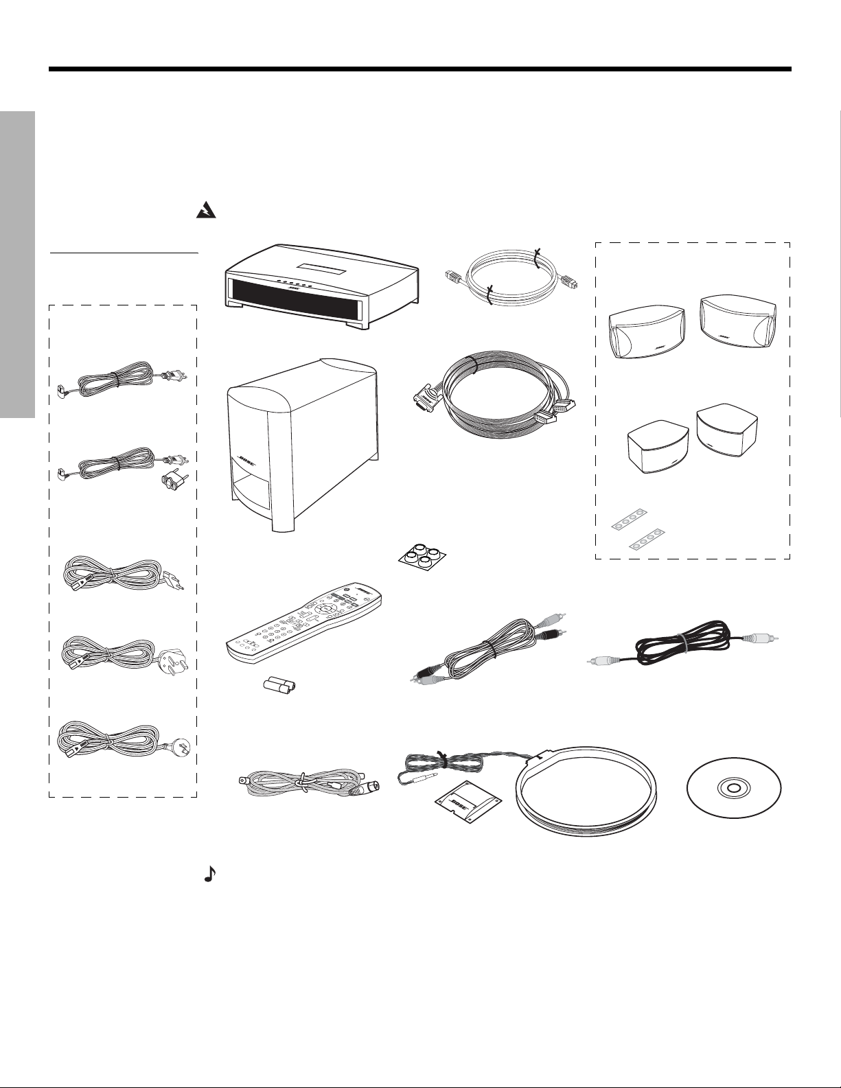
Carefully unpack your system. Save all packing materials, which provide the safest way to
transport your system. Check to be sure your system includes the parts shown in Figure 1.
SYSTEM SETUP
Figure 1
Contents of the shipping
carton
Your system includes
one of the following
cords:
120 VAC power cord
(U.S./Canada)
115/230 VAC power
cord with adapter
(U.S./Europe)
If any part of the system appears damaged, do not attempt to use it. Notify Bose or your
authorized Bose
®
dealer immediately. For Bose contact information, refer to the address
sheet included in the carton.
WARNING:
Media center
To avoid danger of suffocation, keep the plastic bags out of the reach of children.
Your system includes one the
following speaker types:
cable
®
module
3•2•1 speakers
or
3•2•1 GS speakers
Rubber feet for
speakers
Acoustimass
module
Acoustimass
Speaker cable
Note: If you purchased a 3•2•1
GS Series II system, the left and
right speaker cable connectors
will be marked with a “GS”.
Rubber feet for
Acoustimass
module
230 VAC power cord
(Europe)
230 VAC power cord
(U.K./Singapore)
240 VAC power cord
(Australia)
Remote
control
Batteries
FM antenna
Stereo cable
AM antenna
Antenna stand
Video cable
Setup and
demo disc
Note: Now is a good time to find the serial numbers on the bottom of the media center and
Acoustimass module. Copy these numbers onto your product registration card and in the space
provided on page 7.
8
Page 9
Dansk Italiano SvenskaDeutsch NederlandsEnglish FrançaisEspañol
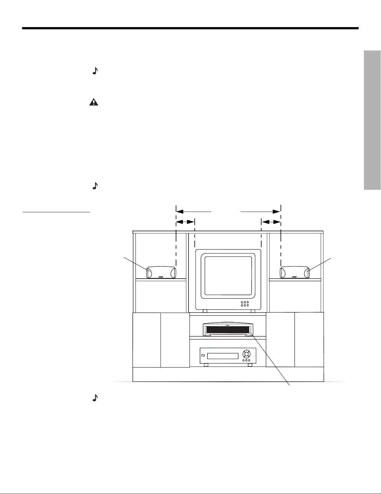
Selecting locations for your 3•2•1 Series II system components
SYSTEM SETUP
Figure 2
Sample media center and
speaker placement
Use the following guidelines and Figure 2 to choose locations and positions for the components of your 3•2•1 home entertainment system.
Note:
While these guidelines are offered to help provide great system performance, you may find
other placement choices that are more convenient and provide the sound you enjoy.
Placing the media center
CAUTION: Do not block any ventilation openings. For reliable operation of the product and to
protect it from overheating, put the product in a position and location that will not interfere with its
proper ventilation. For example, do not place the product on a bed, sofa, or similar surface that
may block the ventilation openings. Do not put it in a built-in system, such as a bookcase or cabinet that may keep air from flowing through its ventilation openings.
• Place the media center where nothing obstructs opening the disc tray on its front panel.
• Make sure the media center will be placed close enough to the Acoustimass
the speakers so that all the cables will reach.
• Make sure the media center will be placed close enough to additional source devices (TV,
VCR or cable box) so that all the cables will reach.
Note:
Make sure that the front of the media center is unobstructed so that it may receive
IR (infrared) commands from the remote control.
3 ft (1 m)
3 ft (1 m)
maximum
minimum
3 ft (1 m)
maximum
®
module and
SYSTEM SETUP
Left
speaker
Media center
Right
speaker
Note: The speakers are magnetically shielded to prevent interference with the TV screen.
9
Page 10
SYSTEM SETUP
SYSTEM SETUP
DanskItalianoSvenska DeutschNederlands EnglishFrançais Español
Placing the speakers
Choosing a good location for the speakers will allow you to experience the audio surround
effects that your 3•2•1 home entertainment system is designed to deliver.
• Place the two speakers either on top of the TV or at equal distance from the left and right of
the TV screen (Figure 2). Keep both speakers at approximately the same height.
• Place each speaker within 3 feet (1 meter) of the edge of the TV screen. Placing the
speakers more than 3 feet away from the TV can cause the sound to become separated
from the picture.
• If you are using a bookshelf or a home entertainment unit, place each speaker at the
front edge of its shelfPositioning the speakers too far back in an enclosed space can
change the overall quality of sound and alter the movie sound effects.
• Place the speakers at least 3 feet (1 meter) apart from each other to optimize the
surround sound experience.
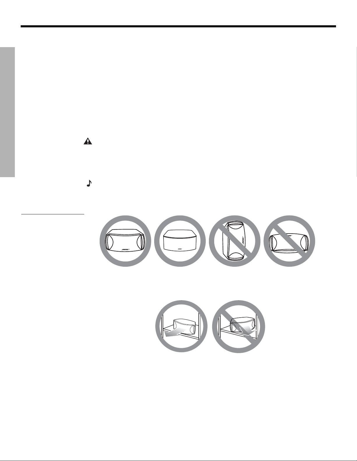
Figure 3
Recommended speaker
placement
CAUTION:
Choose a stable and level surface for both speakers. Vibration can cause the speakers to move, particularly on smooth surfaces like marble, glass, or highly polished wood. If you
are placing the speakers on a flat surface, be sure to attach the smaller of the two sets of supplied rubber feet to the bottom surface. You may obtain additional rubber feet (part number
178321) from Bose
®
Customer Service. To contact Bose, refer to the list of offices included in the
product carton.
Note:
The speakers can be mounted on Bose brackets, table stands, or floor stands. For ordering information, refer to “Accessories” on page 54. Additional or longer cables may also be
ordered.
• Place the speakers only on their bottom surfaces, with the Bose logo right-side up.
• Aim the speakers straight ahead toward the listening area. Do not place the speakers at an
angle. Angling one or both speakers into or away from the listening area signifi-
cantly alters system performance.
10
Page 11
Dansk Italiano SvenskaDeutsch NederlandsEnglish FrançaisEspañol
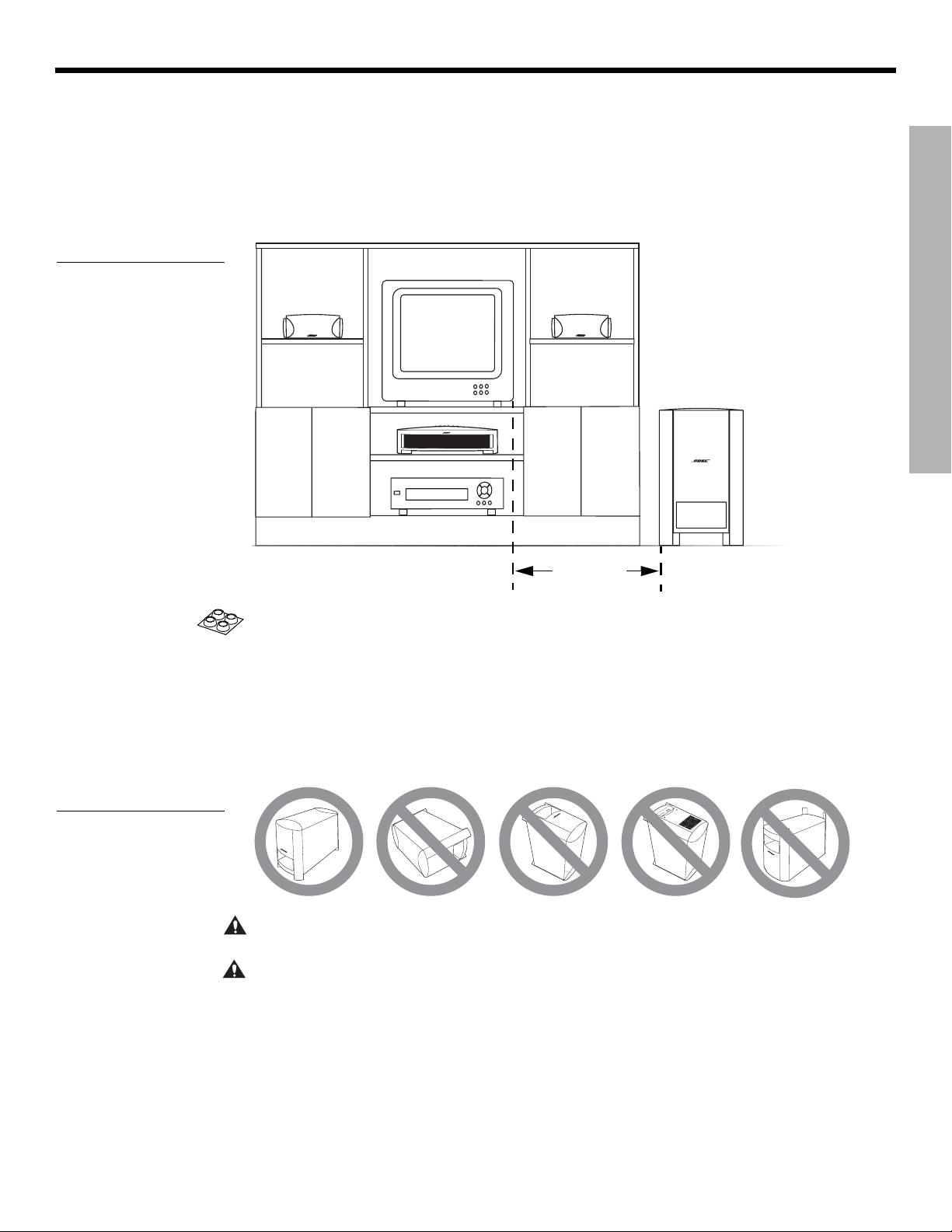
Figure 4
Recommended
Acoustimass module
placement
SYSTEM SETUP
Placing the Acoustimass® module
• Place the Acoustimass® module within reach of the cable from the music center and an AC
(mains) power outlet.
• Place the module at the same end of the room as the TV and the speakers (Figure 4).
• Keep the module at least 3 feet (1 meter) away from the TV to prevent the module from
interfering with the TV screen.
SYSTEM SETUP
Figure 5
Recommended orientation
of the module
3 ft (1 m)
minimum
• Attach the medium-sized rubber feet to the bottom of each foot on the module. The rubber
feet provide increased stability and protection from scratches.
• Choose a convenient location such as under a table, behind a sofa or chair, or behind
drapes, but do not block the port opening.
• Aim the port of the module into the room or along the wall. This prevents a blocked port or
over-powering bass.
• Stand the Acoustimass module on its feet. Do not lay it on its side or stand it on either end
(Figure 5).
A
C
I
N
P
U
T
M
U
S
I
C
C
E
N
T
E
R
CAUTION: Do not block the openings on the back of the module, which provide ventilation for
the built-in circuitry.
CAUTION:
The Acoustimass module generates a magnetic field. Although this is not an immediate risk to your video tapes, audio tapes, and other magnetic media, you should not store any of
these items directly on or near the module.
11
Page 12
SYSTEM SETUP
Making system connections
CAUTION: Do not plug the Acoustimass® module into an AC power (mains) outlet until all the
components are connected.
Note:
If additional audio cables or longer cables are needed to make these connections, contact
Bose Customer Service. Refer to the list of offices included in the product carton.
DanskItalianoSvenska DeutschNederlands EnglishFrançais Español
SYSTEM SETUP
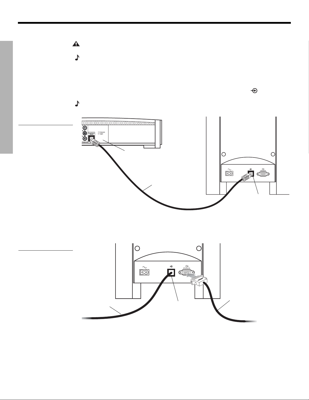
Figure 6
Acoustimass module-tomedia center connection
Connecting the Acoustimass module to the media center
Plug one end of the Acoustimass module cable into the
of the media center (Figure 6). Plug the other end of the cable into the input (
rear of the Acoustimass module.
Note:
The jacks for the Acoustimass module cable are keyed so that the cable connectors only plug
in one way. Make sure that the arrow on the connector body faces up when plugging in the cable.
Media center
rear panel
Acoustimass
module cable
Acoustimass Module
jack on the rear
) jack on the
Acoustimass
module input
jack
Connecting the speakers to the Acoustimass module
1. Insert the single-plug end of the speaker cable into the SPEAKERS jack on the rear
panel of the Acoustimass module (Figure 7). Tighten both screws on the plug.
Figure 7
Speaker cable-toAcoustimass module
connection
12
Acoustimass
module cable
Speaker
cable
Acoustimass
module input
jack
Page 13
Dansk Italiano SvenskaDeutsch NederlandsEnglish FrançaisEspañol
Figure 8
Separating left and right
speaker cords
SYSTEM SETUP
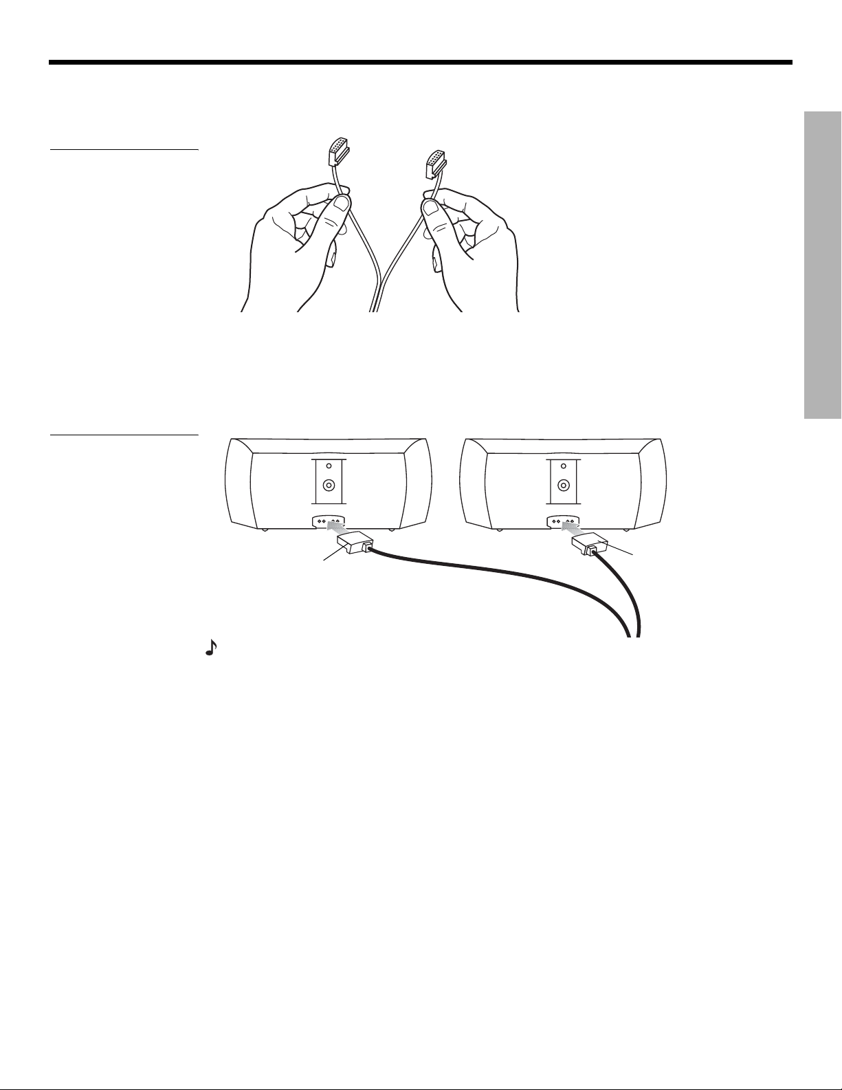
2. At the other end of the speaker cable, separate the left and right speaker cords as much
as necessary to reach each speaker (Figure 8).
SYSTEM SETUP
Note: If you purchased a 3•2•1
GS Series II system, the left and
right speaker cable connectors
will be marked with a “GS”.
3. Plug the LEFT speaker cable into the rear jack of the left speaker (Figure 9). Plug the
RIGHT speaker cable into the rear jack on the right speaker.
Figure 9
Left and right speaker
connections
T
RIGHT
speaker
cable
H
RI G
T
EF
L
LEFT
speaker
cable
Note: Make sure cable connectors are fully inserted and seated firmly in the speaker jacks.
13
Page 14
SYSTEM SETUP
Figure 10
Antenna connections
DanskItalianoSvenska DeutschNederlands EnglishFrançais Español
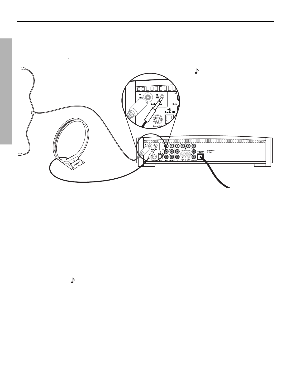
Connecting the supplied antennas
The rear panel of the media center provides jacks for the AM and FM antennas included with
your system (Figure 10). Unwind the wires for each antenna to provide the best reception.
SYSTEM SETUP
FM dipole
antenna
Note: An outdoor antenna may be
used in place of the supplied indoor
antennas. To add an outdoor
antenna, consult a qualified installer.
Follow all safety instructions supplied with the antenna.
Media center
AM loop antenna
FM antenna
Plug the FM antenna into the FM jack on the media center rear panel. Spread out the antenna
arms and move them around to establish optimum FM reception. Extend the antenna as far
from the media center and other equipment as possible.
AM antenna
Plug the AM loop antenna into the AM jack on the media center rear panel. Place the antenna
loop at least 20 inches (50 centimeters) away from the media center and at least 4 feet (1.2
meters) away from the Acoustimass
®
module. Experiment with positioning the loop for optimum AM reception. Follow the instructions enclosed with the AM loop antenna to stand it on
the supplied base, or mount it to a wall.
Connecting cable FM radio
Some cable TV providers make FM radio signals available through the cable service to your
home. This connection is made to the external FM jack on the back panel of the media center. To connect to this service, contact your cable TV provider for assistance.
Note:
Make sure that the cable radio installation includes a TV/FM splitter so that only the
FM radio band, not the cable TV band, is received by the media center. If necessary, contact your
cable company.
14
Page 15
Dansk Italiano SvenskaDeutsch NederlandsEnglish FrançaisEspañol
Connecting your TV to the media center
SYSTEM SETUP
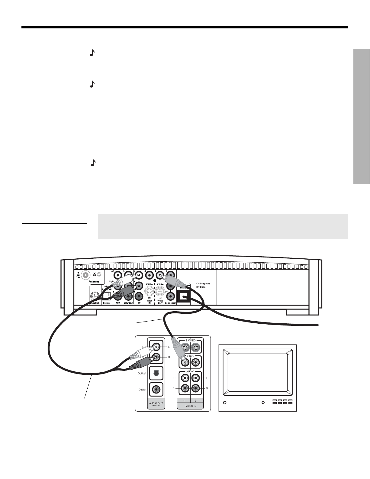
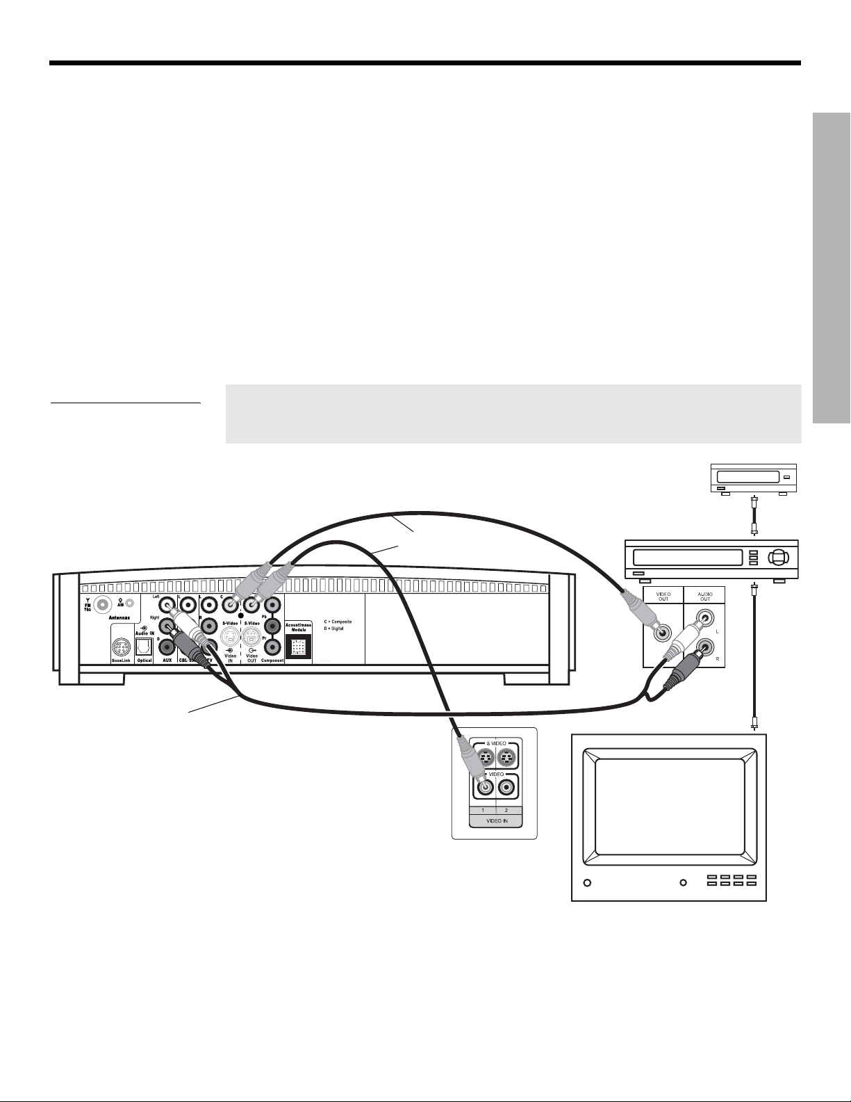
Figure 11
TV (composite video)-tomedia center connections
Note: If you will be using the 3•2•1 system with both a TV and a VCR, skip this section and go
to “Connecting your TV and VCR to the media center” on page 16.
Making audio connections
Note: If your TV does not have audio output jacks, see “If your TV does not have audio output
jacks” on page 17
1. Connect one end of the supplied stereo cable to the TV Audio IN jacks on the rear panel
of the media center (Figure 11). Insert the white RCA plug into the TV white L jack. Insert
the red RCA plug into the TV red R jack.
2. Connect the other end of the stereo cable to the audio output jacks on your TV. Insert the
white RCA plug into the white AUDIO OUT L jack. Insert the red RCA plug into the red
AUDIO OUT R jack.
. Otherwise, continue.
Making composite video connections
Note: Some older TVs with standard TV cable connectors do not have a composite video or an
S-video input. Such TVs are not compatible with any DVD players and require use of an RF modulator for this connection. RF modulators are available at your local electronics store.
1. Insert one end of the supplied video cable (yellow) to the Video OUT C (composite) jack
on the back of the media center (Figure 11).
2. Insert the other end of the video cable into one of the video input jacks on your TV.
Write the name of the video input jack used on your TV in the box on page 25. After
you turn on the system, you will need to select this video input on your TV in order
to view the 3•2•1 system video output.
SYSTEM SETUP
Video cable
(yellow connectors)
Stereo cable
(red and white connectors)
Media center rear panel
TV connector panel
TV
*
*Could be labelled “FIXED”, “MONITOR”, or “HiFi”.
15
Page 16
SYSTEM SETUP
Connecting your TV and VCR to the media center
Note: There are two options for connecting your TV and VCR to the media center. Before you
proceed, you must determine if your TV has audio output jacks. Consult your TV owner’s guide if
you need assistance.
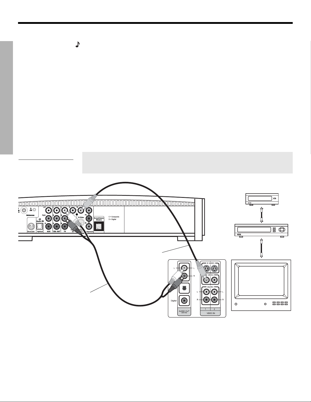
If your TV has audio output jacks
SYSTEM SETUP
If your TV has audio output jacks, you can directly route the TV audio to the 3•2•1 home
entertainment system (Figure 12).
1. Connect one end of the supplied stereo cable to the TV Audio IN jacks on the rear panel
of the media center. Insert the white RCA plug into the TV white L jack. Insert the red
RCA plug into the TV red R jack.
2. Connect the other end of the stereo cable to the audio output jacks on your TV. Insert the
white RCA plug into the white AUDIO OUT L jack. Insert the red RCA plug into the red
AUDIO OUT R jack.
3. Insert one end of the supplied video cable (yellow) to the Video OUT C (composite) jack
on the back of the media center. Insert the other end of the video cable into one of the
video input jacks on your TV.
DanskItalianoSvenska DeutschNederlands EnglishFrançais Español
Figure 12
TV and VCR connections
with media center
Stereo cable
(red and white connectors)
Write the name of the video input jack used on your TV in the box on page 25. After
you turn on the system, you will need to select this video input on your TV in order
to view the 3•2•1 system video output.
Cable/satellite box
(if applicable)
Existing
Video cable
(yellow connectors)
TV connector
panel
cable
Existing
cable
VCR
TV
16
*
*Could be labelled “FIXED”, “MONITOR”, or “HiFi”.
Page 17
Dansk Italiano SvenskaDeutsch NederlandsEnglish FrançaisEspañol
SYSTEM SETUP
If your TV does not have audio output jacks
If your TV does not have audio output jacks, you will need to feed audio to the 3•2•1 home
entertainment system through a secondary source, such as a VCR. To do this, you will need
one additional video cable, which can be purchased at your local electronics store.
1. Connect one end of the supplied stereo cable to the AUX Audio IN jacks on the rear
panel of the media center (Figure 13). Insert the white RCA plug into the AUX white L
jack. Insert the red RCA plug into the AUX red R jack.
2. Connect the other end of the stereo cable to the AUDIO OUT jacks on your VCR. Insert
the white RCA plug into the white AUDIO OUT L jack. Insert the red RCA plug into the
red AUDIO OUT R jack.
3. Insert one end of the supplied video cable (yellow) into the VIDEO OUT jack on the
back of your VCR. Insert the other end of the supplied video cable into the Video IN C
(composite) jack on the back of the media center.
4. Insert one end of the second video cable (yellow) into the Video OUT C (composite) jack
on the back of the media center. Insert the other end of the second video cable into one
of the video input jacks on your TV.
SYSTEM SETUP
Figure 13
System setup when TV has
no audio output jacks
Media center rear panel
Stereo cable
(red and white connectors)
Write the name of the video input jack used on your TV in the box on page 25. After
you turn on the system, you will need to select this video input on your TV in order
to view the 3•2•1 system video output.
IMPORTANT
If you connected your TV and VCR this way, you
will need to turn on your VCR and select the
AUX source on the 3•2•1 remote to hear sound
from TV programs.
Video cables
(yellow connector)
TV connection panel
Cable/satellite box
VCR
TV
Existing
cable
VCR
connection
panel
Existing
cable
17
Page 18
SYSTEM SETUP
SYSTEM SETUP
Advanced setup options
DanskItalianoSvenska DeutschNederlands EnglishFrançais Español
VCR considerations
• Some combination TV/VCR units may not work with 3•2•1 Series II home entertainment
systems. Please refer to your TV/VCR owner’s manual for information.
• A stereo VCR is required for optimal sound performance. If your VCR has only one audio
output and is not labeled Stereo or Hi-fi, you have a mono VCR. You will need a
Y-adapter cable (available at electronics stores) to connect audio to the media center. For
this setup, you will need to select “Mono decoding” (see “TV, CBL•SAT, and AUX settings
menu” on page 44) so your 3•2•1 system will simulate surround sound effects from a mono
source. Otherwise, you will hear mono sound from both speakers.
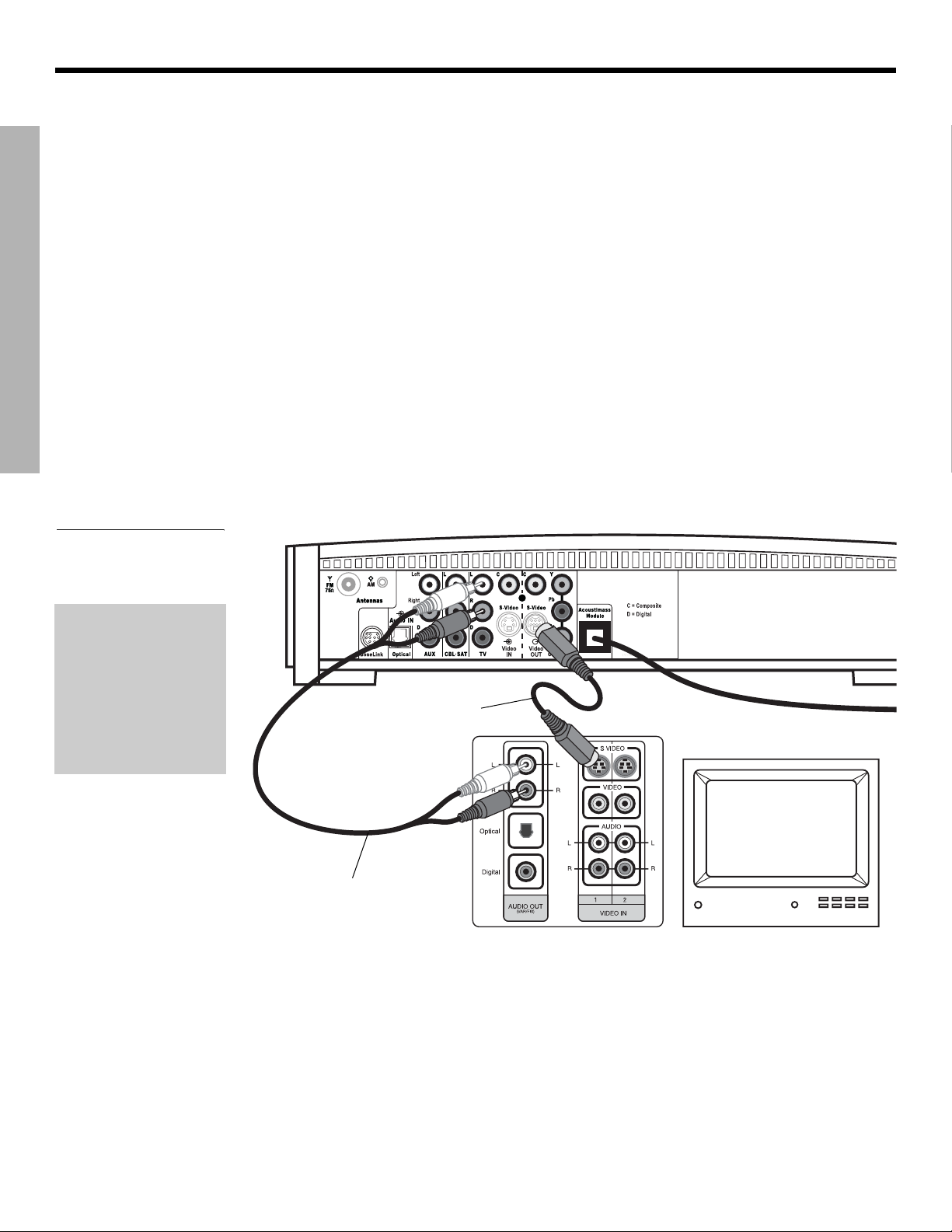
Making S-video connections (higher quality video)
An S-video input jack, provided on many TVs, delivers a higher quality TV picture than the
composite video output connection shown in Figure 11. For this connection you will need an
S-video cable which can be purchased from your Bose dealer or a local electronics retailer.
• Insert one end of the S-video cable into the S-Video OUT jack on the media
center (Figure 14).
• Insert the other end of the S-video cable into the S-VIDEO IN jack on your TV.
Figure 14
TV (S-video)-to-media
center connections
IMPORTANT
If you use S-video to
connect your TV to the
media center, you
must also use S-video
to connect all other
devices (such as a
cable box and VCR) to
the media center.
Media center rear panel
S-video cable
TV connector panel
TV
Stereo cable
(red and white connectors)
18
Page 19
Dansk Italiano SvenskaDeutsch NederlandsEnglish FrançaisEspañol
SYSTEM SETUP
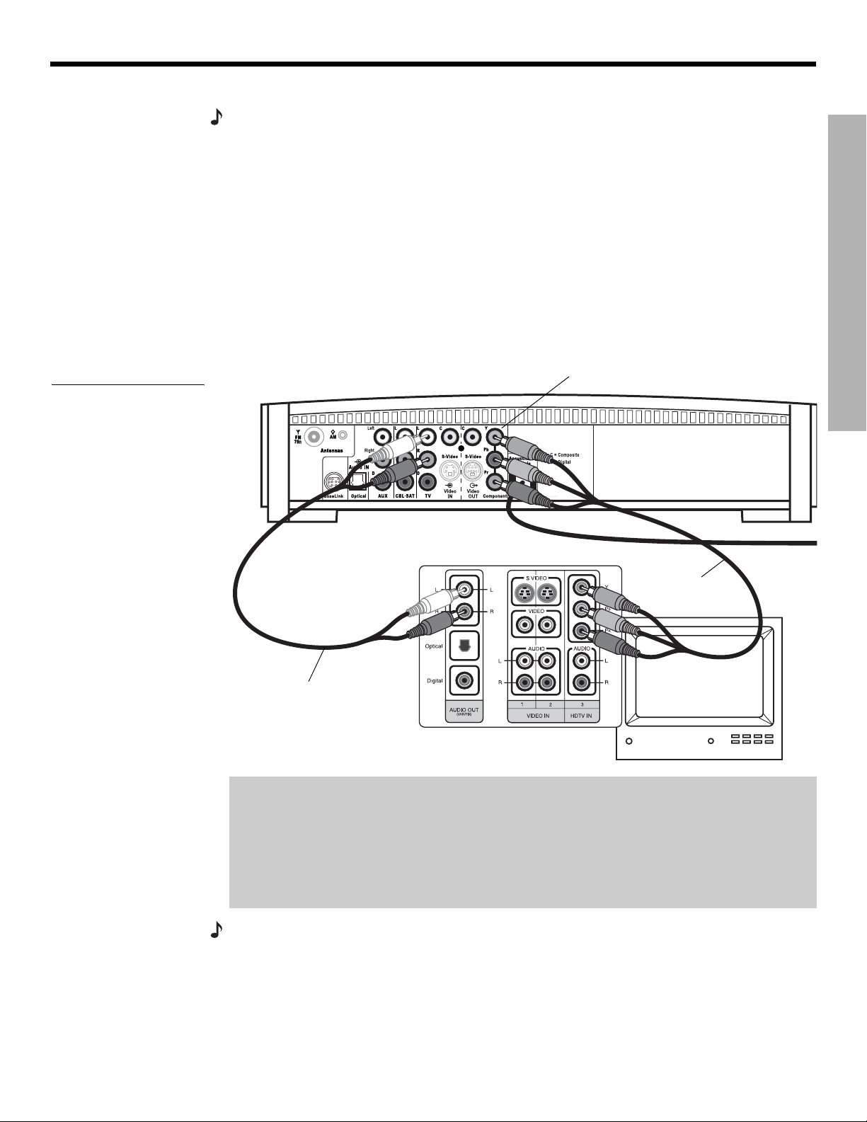
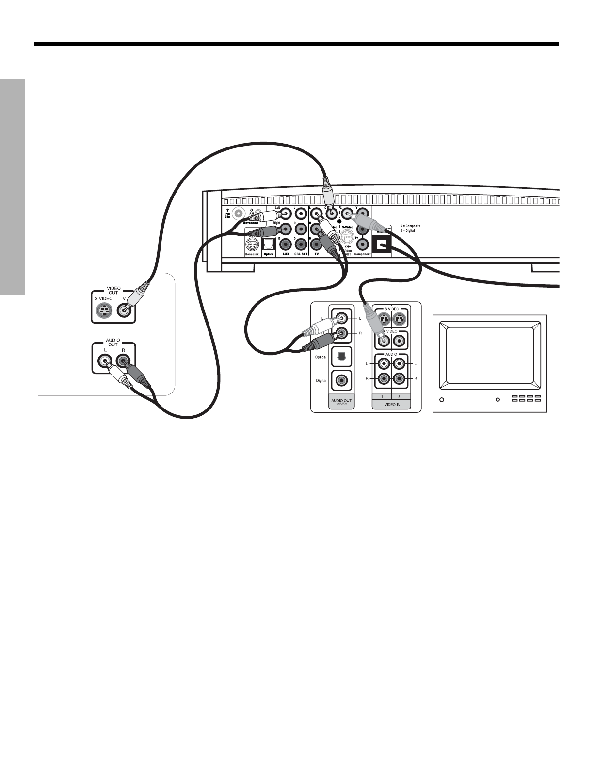
Making component video connections (highest quality video)
Note: Component video connections are required in order to use the progressive scan feature of
your 3•2•1 system. Your TV must also support this feature. To turn on the progressive scan feature, see “Video options” on page 48.
For the highest quality video from DVDs, you may want to use a component video connection
between the media center and the TV. To do so, your TV must provide component video jacks
(typically labelled Y, Pb, and Pr). Refer to your TV owner’s guide for more information.
To make component video connections you will need three video grade cables that are long
enough to reach from the rear of the media center to your TV (Figure 15). If the cables are not
supplied with your TV, you can purchase them separately.
1. On the media center rear panel, plug one video cable into the Component Y, Pb, and Pr
video output jacks (Figure 15).
2. Plug the other end of each video cable into the corresponding (color or letter code) com-
ponent video jack on the back of your TV.
SYSTEM SETUP
Figure 15
TV (component video)-tomedia center connections
Media center rear panel
Stereo cable
(red and white connectors)
Color-coded component video
jacks (Y, Pb, and Pr)
TV connector panel
Component
video cable
IMPORTANT FOR COMPONENT VIDEO USERS
Input signals received by the C (Composite) or S-Video IN jacks are not passed through to
the Component video OUT jacks. If you connect an external video device to the C or
S-Video IN jack, you must also connect the C or S-Video OUT jack on the media center to
the respective video input jack on your TV. To view the external video input on your TV, you
will need to select the TV video input used for that device. To view the onscreen menus of
the 3•2•1 system, you will need to switch back to the TV’s component video input.
Note:
For more information, or to purchase the video cables, contact your local electronics store
or authorized Bose dealer.
19
Page 20
SYSTEM SETUP
SYSTEM SETUP
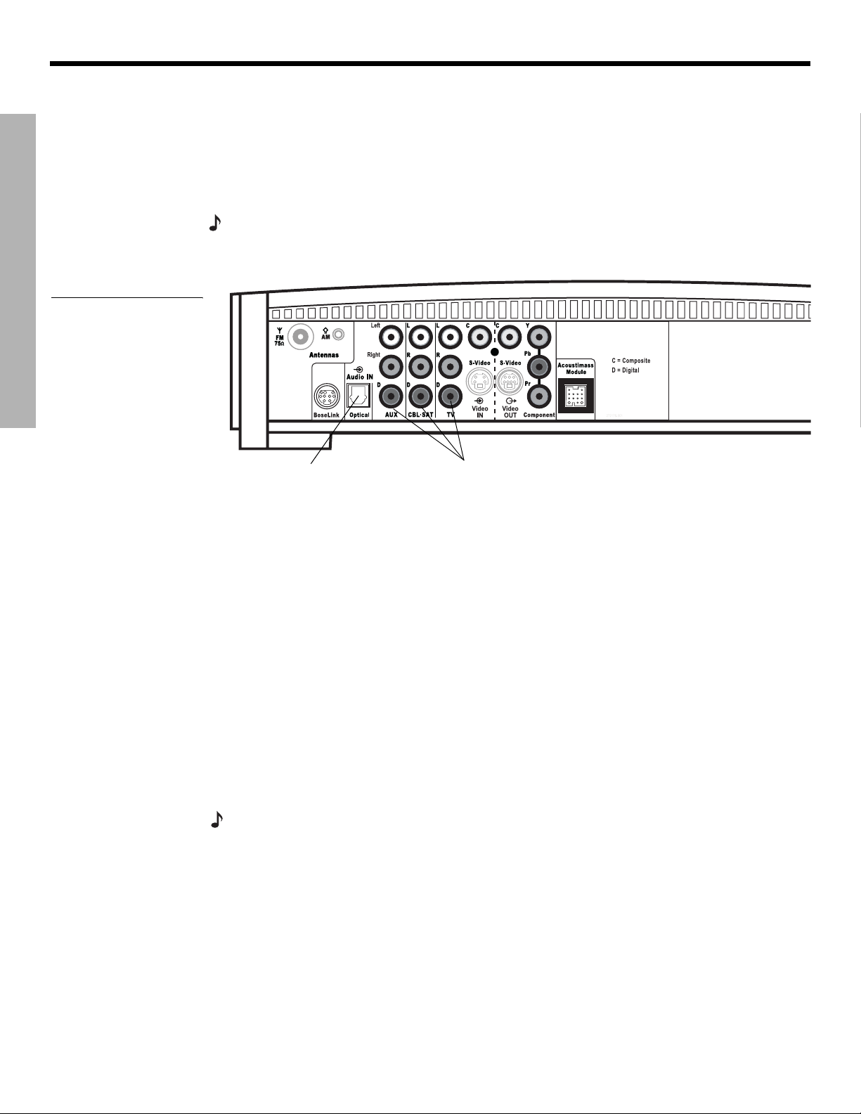
Figure 16
Media center digital audio
input jacks
DanskItalianoSvenska DeutschNederlands EnglishFrançais Español
Connecting digital audio devices
Some audio devices may feature a digital audio output for optimum sound performance. Use
an optical digital cable or a coaxial digital cable, as appropriate, to connect this output to the
digital input on the media center. You can purchase the required cables at a local electronics
store.
On the media center rear panel, an optical digital cable connects to the OPTICAL jack. A
coaxial cable connects to the audio input jacks labeled D.
Note:
Before you can benefit from the optical connection, you will need to assign the optical
connector to the audio source in the system settings menu. See “Media center options” on
page 49.
Optical digital
audio input
Coaxial digital
audio inputs
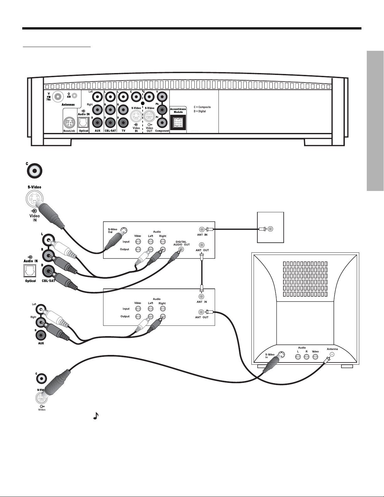
Connecting your cable/satellite box, TV, and VCR to the media center
The 3•2•1 home entertainment system provides flexibility for you to add up to three external
audio devices, including your TV, directly to the media center.
Figure 17 shows you an advanced setup using a TV, VCR and cable/satellite box. In this
setup, please notice the following:
• S-video connections are used to deliver the cable/satellite signal to the media center.
Therefore, the media center output video is sent to the TV also through an S-video
connection.
• Analog and digital coax audio connections are shown for the cable/satellite box. As an
option, you may use an optical digital connection. However, before you can benefit from the
optical connection, you will need to assign the optical connector to the cable/satellite box
audio source in the system settings menu. See “Media center options” on page 49.
• When connecting an audio device to the media center jacks, remember to match the red
jack to the right channel (R) and the white (or black) jack to the left channel (L).
• For further details on making the video connections between your VCR and TV, refer to the
manuals for these video devices.
Note:
The recommendations contained in this owner’s guide are basic suggestions for connecting external devices to the 3•2•1 Series II system. Instructions and terminology pertinent to these
external devices may vary, depending on the manufacturer. Consult the owner’s guide that came
with the device for clarification on setup and usage before making any connections.
20
Page 21
Dansk Italiano SvenskaDeutsch NederlandsEnglish FrançaisEspañol
Figure 17
Advanced setup: TV, VCR
and cable
satellite box
SYSTEM SETUP
SYSTEM SETUP
Media center
CBLSAT
S-video
output
CBLSAT analog
audio
VCR analog audio
Cable/satellite
CBLSAT
digital audio
VCR
Media center’s
S-video output
to TV
SAT
CBL
signal to
VCR
CBLSAT
signal to
TV
Cable/satellite
(CBL
SAT)
service
TV
Note: For more information on advanced connections, refer to the DVD setup disc that came
with your 3•2•1 Series II home entertainment system.
21
Page 22
SYSTEM SETUP
Figure 18
Game console connections
SYSTEM SETUP
Game console
connection panel
DanskItalianoSvenska DeutschNederlands EnglishFrançais Español
Connecting a game console
Connect the audio output of a game console to the AUX Left and Right input jacks. Connect the video output of the game console to the C (composite) Video IN jack.
Media center
TV connection panel
IMPORTANT
If you connected your game console this way, you will
need to select the AUX source on the 3•2•1 remote in
order to hear sound from the game console.
22
Page 23
Dansk Italiano SvenskaDeutsch NederlandsEnglish FrançaisEspañol
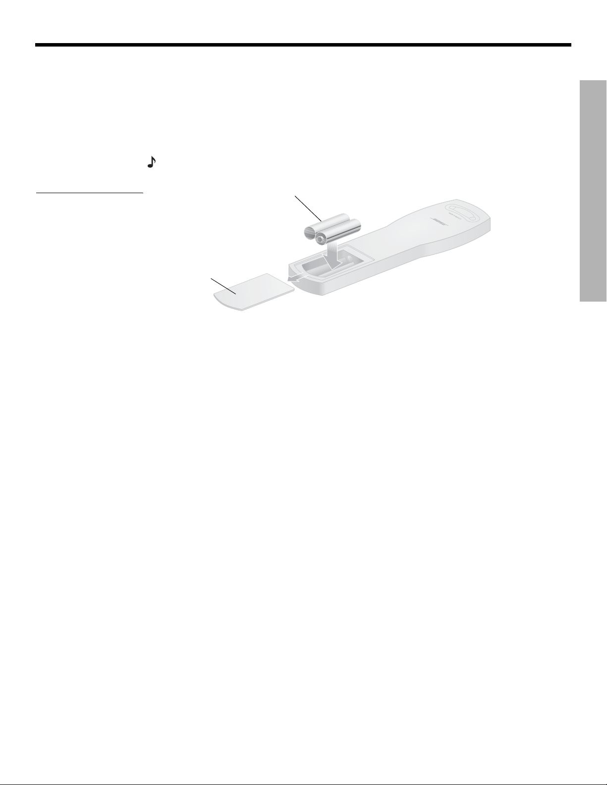
Installing the remote control batteries
SYSTEM SETUP
Figure 19
Installing the batteries
1. On the back of the remote, slide open the battery compartment (Figure 19).
2. Insert the two supplied AA (IEC-R6) 1.5V batteries, or their equivalent, as shown. Match
the plus (+) and minus (–) marked on the batteries with the plus (+) and minus (–) inside
the battery compartment.
3. Slide the battery compartment cover back into place.
Note:
R
eplace the batteries when the remote control stops operating or its range seems reduced.
(2) AA batteries (IEC-R6)
Battery
compartment
door
SYSTEM SETUP
23
Page 24
SYSTEM SETUP
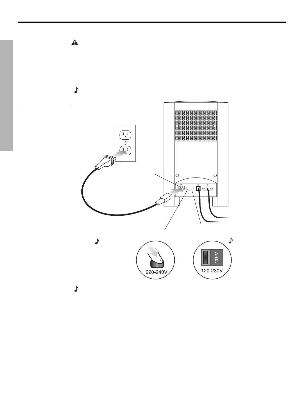
Connecting the power cord
DanskItalianoSvenska DeutschNederlands EnglishFrançais Español
SYSTEM SETUP
Figure 20
Connecting to power
CAUTION: For dual voltage models only, be sure to set the dual voltage switch on the back of
the Acoustimass
®
module to the appropriate voltage for your area (115V or 230V) before connecting to power. If you are not sure about the proper voltage for your area, consult your local
electrical authorities.
1. Insert the small connector end of the power cord into the AC INPUT connector on the
Acoustimass module (Figure 20).
2. Insert the large end of the cord into an AC power (mains) outlet.
Note:
On 220-240V models only, turn the Acoustimass module POWER switch to on (l).
AC input
jack
AC power
switch
Note: Provided
only on 220-240V
rated systems.
115/230V
selection
switch
Note: Provided
only on 115/230V
dual voltage rated
systems.
Note: Bose recommends using a safety agency-approved surge protector on all electronic
equipment. Voltage variations and spikes can damage electronic components in any system.
A quality suppressor can eliminate the vast majority of failures attributed to surges and may be
purchased at electronics stores.
24
Page 25

Dansk Italiano SvenskaDeutsch NederlandsEnglish FrançaisEspañol
Checking your system setup
SYSTEM SETUP
Follow these steps when turning on your system for the first time. Be sure to perform step 4
and play the setup DVD. The setup DVD can help you verify that you set up your system correctly for proper sound performance.
1. Check the following before you continue:
• All cables are connected for the setup you chose.
• The batteries were installed in the remote control.
• The power cord was installed and plugged into a live AC receptacle.
2. Turn on your TV. Use the remote control that came with your TV.
3. Using your TV remote, select the video input on your TV that connects to the
video output of the media center.
Name TV video input used:
• The method of selecting the right video input depends on your TV. Refer to your TV
owner’s guide for help.
4. Play the 3•2•1 setup DVD.
A. Turn on your 3•2•1 system. Point the 3•2•1 remote control at the media center and
press On-Off.
B. Press Eject on the media center control panel.
C. Insert the DVD setup disc into the disc tray.
D. Press Eject again to close the tray. The DVD will automatically begin to play. If it does
not, press the play button (
).
SYSTEM SETUP
5. Turn off the TV speakers.
• Refer to your TV owner’s guide for help.
• If your TV does not have an option to turn off the internal speakers, you may need to
adjust both the 3•2•1 system volume and your TV volume until you find a level that produces the desired sound.
• In some TVs, when the internal speakers are turned off, you may need to raise the TV’s
volume level by 75% to 100% in order to hear audio from the 3•2•1 home
entertainment system. See your TV owner’s guide for help.
Note:
Be sure to play the setup DVD, included in the carton with your system, as soon as all the
connections are completed. This will help you verify the connections you have made and confirm
proper sound performance.
25
Page 26

SYSTEM CONTROLS AND INDICATORS
Remote control
DanskItalianoSvenska DeutschNederlands EnglishFrançais Español
Remote
status
LED
SYSTEM CONTROLS AND INDICATORS
• Turns the system on or off.
Status LED:
• Remains off (unlit) during normal operation.
• Remains on during setup mode. Turns off briefly with each key press.
• Blinks rapidly eight times if the wrong key is pressed during setup or if an
unavailable device code is entered.
• After ten seconds of no key presses, blinks rapidly eight times and the remote
exits the setup mode.
• Silences or restores the sound from the current source.
• Selects the built-in CD/DVD player and turns the system on.
• Selects the built-in tuner and turns the system on to the previously selected FM/
AM station.
• Switches between FM and AM when the tuner is selected.
• TV: Turns your system on and selects the TV input as the sound source.
• Input: Changes the external input to your TV. For example, your TV
might have two external inputs where one is connected to your cable
box and the other to your VCR. Pressing this button alternates between
the cable box and the VCR.*
• On/Off: Turns your TV on and off.*
• CBLSAT: Turns your system on and selects the CBLSAT input as the sound
source.
• On/Off: Turns your cable/satellite box on or off.*
AUXAUX
• AUX: Turns your system on and selects the AUX input as the sound source.
• On/Off: Turns a VCR or DVR that is connected to the AUX jack on or off.*
* Requires special remote settings. See “Setting up your remote to control other audio/video devices”
on page 30.
26
Page 27

Dansk Italiano SvenskaDeutsch NederlandsEnglish FrançaisEspañol
Remote control – cont.
SYSTEM CONTROLS AND INDICATORS
• Puts the Settings menu for the current source on your TV screen or media
center display.
• Puts the System menu on your TV screen.
• Puts the DVD menu of the currently loaded DVD disc on your TV screen.
• Puts the main menu of a cable/satellite box, VCR, or DVR on your TV
screen (if supported).*
• Puts the TV, cable, satellite, or DVR program guide (if supported) on your
TV screen.
• Removes the Settings and System menus from your TV screen.
• Removes on-screen menus for TV, cable/satellite box, or VCR/DVR from
your TV screen.*
• Tunes the FM or AM radio to the next higher or lower frequency.
• Selects the next item, up or down, in menus.
SYSTEM CONTROLS AND INDICATORS
• Confirms a menu selection or introduces the next level of menu options.
• Moves up, down, left, or right in onscreen menus and media center
displays.
*Requires special remote settings. See “Setting up your remote to control other audio/video devices” on
page 30.
27
Page 28

SYSTEM CONTROLS AND INDICATORS
Remote control – cont.
SYSTEM CONTROLS AND INDICATORS
DanskItalianoSvenska DeutschNederlands EnglishFrançais Español
• Raises or lowers the volume of the current source.
• Pressing + restores muted sound from the current source.
• Pressing – lowers the volume of the current source, but does not restore
muted sound.
• Skips to the next or previous TV channel,* CD track, or DVD chapter.
• Stops the disc player.
•
For DVDs only
tion. Pressing
Pressing
• Pauses a currently playing disc.
• Pressing
• After 20 minutes of no user interaction, the disc player stops and returns
to the beginning of the disc to wait for the next command.
, the disc stops and the system saves the DVD play posi-
continues the DVD from the saved play position.
twice for a disc in play returns to the beginning of the disc.
again (or pressing ) resumes play of a paused disc.
• Starts the disc player.
• Skips backward or forward through CD tracks.
• Skips backward or forward through DVD chapters.
• Seeks backward or forward to the next strongest radio station.
• Plays audio CD tracks in random order. Press again to cancel this mode.
• Starts instant replay (
• Repeats a CD, CD track, DVD chapter, or DVD title. Press again to
change the repeat mode.
• Initiates Quick Skip and/or Return to Live (
• Provides a means for selecting a CD track, DVD chapter, radio station
preset, or TV channel.
• Allows you to change numerical values for some menu options.
• Displays or exits the TV, cable, satellite box, or VCR/DVR information on
your TV screen.*
• During MP3 play, removes or restores track information on the media
center display.
• Skips to the previous TV channel (if supported by your TV).
) for DVR (if supported).
) for DVR (if supported).
28
• Skips ahead (Page up) or back (Page down) one page in the Electronic
Program Guide (if supported).
* Requires special remote settings. See “Setting up your remote to control other audio/video devices”
on page 30.
Page 29

Dansk Italiano SvenskaDeutsch NederlandsEnglish FrançaisEspañol
Remote control – cont.
SYSTEM CONTROLS AND INDICATORS
SYSTEM CONTROLS AND INDICATORS
Aspect ratio or Teletext On/Off control
You will see one of two symbols below this button on your remote control. The symbol
defines the function.
Symbol Function
When a video source is selected, changes the video aspect ratio
between Normal (4:3) and Widescreen (16:9).
For Europe, only
When the TV source is selected, turns the Teletext mode on or off.
Recording/Cable or Teletext controls
These four buttons will be marked in one of two ways on your remote.The markings
define how the buttons are used.
Button markings Functions
• When a VCR, DVR or other video recording
device is selected, the Red button activates the
record function.*
Red (Record)
Red
*Requires special remote settings. See “Setting up your remote to control other audio/video
devices” on page 30.
Green
Yellow
Blue
• When a cable source is selected, A, B, and C
are used for cable-related functions.*
For Europe, only
In the Teletext mode, the colored buttons are used
for Teletext-related functions.
29
Page 30

SYSTEM CONTROLS AND INDICATORS
Setting up your remote to control other audio/video devices
Your remote can be set up to control other audio devices such as a TV, VCR, DVR or
cable/satellite box by entering a device code while in the setup mode.
• If you know the device code, follow the instructions under the heading, “Direct
entry of a device code” below. Device codes are listed in the back section of this owner’s
guide and in the System menus under Remote Control options.
• If you can’t find the device code and want to search the system for it, see
“Searching for a device code” on page 31.
• If you want to verify the device code you have entered for an audio device, see
“Verifying an entered device code” on page 33.
• If you want to return to a previous device assignment, press and hold the TV button
until the remote LED is lit (about 5 seconds). On the remote keypad, enter 977.
• If you want to wipe out all assigned codes, press and hold the TV button until the
remote LED is lit (about 5 seconds). On the remote keypad, enter 981.
SYSTEM CONTROLS AND INDICATORS
Note:
More than one code may work with your particular brand of product. If you notice a lack of
response or limited functionality after setting up the remote, try a different code.
Note:
The remote status LED flashes rapidly eight times if you press an invalid key, or enter an
unavailable device code. Wait seven seconds for the error to clear and start again.
DanskItalianoSvenska DeutschNederlands EnglishFrançais Español
Direct entry of a device code
Device codes can be found at the back of this owner’s guide or in the System menu under
Remote Control options. If you know the device code, you can do the following:
To set up the remote to control your TV
1. Turn on both the 3•2•1 system and your TV.
2.
Press and hold the TV button until the remote LED is lit (about five seconds).
3. On the remote keypad, enter the four-digit device code for your TV. The LED will turn off
temporarily as you press each key.
4. Check that the LED turns off after the code is entered. If the LED blinks, the code is
invalid. Try again.
5.
Point the remote at your TV and press the TV On-Off button. If your TV does not
respond, go back to step 2 and try other codes. If you are still unsuccessful, see
“Searching for a device code” on page 31.
Note:
After programming your remote to control external audio/video devices from the System
menu, press the System button once to continue navigating the System menu.
30
Page 31

Dansk Italiano SvenskaDeutsch NederlandsEnglish FrançaisEspañol
AUXAUX
SYSTEM CONTROLS AND INDICATORS
To set up the remote to control your cable/satellite box
1. Turn on both the 3•2•1 system and your cable/satellite box.
2.
Press and hold the CBLSAT button until the remote LED is lit (about five seconds).
3. On the remote keypad, enter the four-digit device code for your cable/satellite box. The
LED will turn off temporarily as you press each key.
4. Check that the LED turns off after the code is entered. If the LED blinks, the code is
invalid. Try again.
5.
Point the remote at your cable/satellite box and press the CBLSAT On-Off button. If
your cable/satellite box does not respond, go back to step 2 and try other codes. If you
are still unsuccessful, see “Searching for a device code” on page 31.
To set up the remote to control your VCR or DVR (such as Tivo or Replay TV brands)
1. Turn on both the 3•2•1 system and your VCR or DVR.
2.
Press and hold the AUX button until the remote LED is lit (about five seconds).
3. On the remote keypad, enter the four-digit device code for your VCR/DVR. The LED will
turn off temporarily as you press each key.
SYSTEM CONTROLS AND INDICATORS
AUXAUX
4. Check that the LED turns off after the code is entered. If the LED blinks, the code is
invalid. Try again.
5.
Point the remote at your VCR or DVR and press the AUX On-Off button. If your VCR or
DVR does not respond, go back to step 2 and try other codes. If you are still unsuccessful, see “Searching for a device code” on page 31.
Searching for a device code
Use this method if you do not know the device code for a device.
Note:
This is a very time-consuming process. Use it as a last resort.
To set up the remote to control your TV
1. Turn on both the 3•2•1 system and your TV.
2.
Press and hold TV until the remote LED is lit (about five seconds).
Alternately press Channel and TV On-Off until your TV turns off.
3.
4.
Press Enter. Check that the remote LED turns off.
5.
Point the remote at your TV and press TV On-Off. If your TV does not respond, go back
to step 2 and try again.
31
Page 32

SYSTEM CONTROLS AND INDICATORS
SYSTEM CONTROLS AND INDICATORS
To set up the remote to control your cable/satellite box
1. Turn on both the 3•2•1 system and your cable/satellite box.
2.
Press and hold CBLSAT until the remote LED is lit (about five seconds).
Alternately press Channel and CBLSAT On-Off until your cable/satellite box
3.
turns off.
4.
Press Enter. Check that the remote LED turns off.
Point the remote at your cable/satellite box and press CBLSAT On-Off. If your cable/
5.
satellite box does not respond, go back to step 2 and try again.
DanskItalianoSvenska DeutschNederlands EnglishFrançais Español
AUXAUX
AUXAUX
AUXAUX
To set up the remote to control your VCR or DVR (for example, TiVo or Replay TV)
1. Turn on both the 3•2•1 system and your VCR/DVR.
2.
Press and hold AUX until the remote LED is lit (about five seconds).
Alternately press Channel and AUX On-Off until your VCR/DVR turns off.
3.
4. Press
5.
Enter. Check that the remote LED turns off.
Point the remote at your VCR/DVR and press AUX On-Off. If your VCR/DVR does not
respond, go back to step 2 and try again.
32
Page 33

Dansk Italiano SvenskaDeutsch NederlandsEnglish FrançaisEspañol
SYSTEM CONTROLS AND INDICATORS
Verifying an entered device code
In case you need to check to see what code the remote is using for a particular audio device,
do the following:
1. Press and hold a source key (TV, CBLSAT, or AUX) until the remote LED lights (about
five seconds)
2.
Press the Info button.
3. Press 1 on the remote and count the number of times the LED blinks (zero is indicated by
a long blink). This is the first digit.
4. Press 2 on the remote and count the number of times the LED blinks (zero is indicated by
a long blink). This is the second digit.
5. Press 3 on the remote and count the number of times the LED blinks (zero is indicated by
a long blink). This is the third digit.
6. Press 4 on the remote and count the number of times the LED blinks (zero is indicated by
a long blink). This is the fourth digit.
7.
Press Exit.
SYSTEM CONTROLS AND INDICATORS
Changing the default TV channel control
With the TV source selected, your remote is set at the factory to select TV channels using
your TV. If you wish to use your VCR or cable/satellite box to select TV channels, you can
change the default setting in your remote.
To change the default TV channel control:
1.
Press and hold Previous on the 3•2•1 remote. The remote status LED will illuminate and
blink once for TV (factory setting), twice for CBL-SAT, or three times for AUX to identify
the default TV channel control.
2. After the blinking stops, press the source button (TV, CBLSAT, or AUX) that
corresponds to the device you want to use for selecting TV channels.
3.
Press Exit on the 3•2•1 remote.
To confirm, press and hold Previous on the 3•2•1 remote and count the number of blinks. If
the change was made, press Exit. If not, repeat steps 2 and 3.
33
Page 34

SYSTEM CONTROLS AND INDICATORS
The media center
The media center has a control panel on the top, a display area to show the current status of
the system, and a disc tray that opens on the front of the console.
Control panel
The media center has six buttons located on the top control panel. Their functions are also
available through use of the remote control.
DanskItalianoSvenska DeutschNederlands EnglishFrançais Español
Figure 21
Media center controls
SYSTEM CONTROLS AND INDICATORS
Figure 22
Sample media center
display
On-Off Source – Volume + Enter Eject
Turns system
power on or
off.
®
Steps through
the available
source
selections.
Lowers or raises
the volume level.
• Used to navigate
through menus.
• Sets next available
AM/FM preset
Opens or
closes the
disc tray.
Note: If you selected another source by pressing the Source button, you cannot control the
new source with the remote until you press the button for that new source on the remote.
Display indicators
With the system turned on, the music center display lights up to show the state of the
system. Not all possible choices, shown below, light up at once (Figure 22). The display
changes with each adjustment or selection you make.
Lights to indicate
DVD 0:06:11
CHAPTER 1/12
Lights to indicate
shuffle mode is
selected for the
current disc.
SHUFFLE REPEAT DISC TRACK
Lights to indicate
repeat mode is
selected for current track or disc.
Lights to indicate
“Repeat Disc” or
“Shuffle Repeat
Disc” mode is
selected.
disc is in play.
Lights briefly when a
remote control command is received.
Lights to indicate
“Repeat Track”
mode is selected.
34
Page 35

Dansk Italiano SvenskaDeutsch NederlandsEnglish FrançaisEspañol
Turning your system on and off
To turn power on or off:
• Point the 3•2•1 remote at the media center and press On/Off.
OR
• Press On-Off on top of the media center.
To turn the system on to a source:
• Press CD-DVD, FM-AM, TV, CBLSAT, or AUX on the 3•2•1 remote.
Note:
Your 3•2•1 remote control can be set up to control other audio devices such as your TV,
VCR, or cable/satellite receiver. For instructions, see “Setting up your remote to control other
audio/video devices” on page 30.
Playing video DVDs
Before you play your first DVD:
• Familiarize yourself with the 3•2•1 remote control. See “Remote control” on page 26.
• Be sure you understand how to switch between the available video inputs on your TV. To
view a video DVD, you will need to select the video input on your TV that is connected to
video output of the 3•2•1 media center (see “Connecting your TV to the media center”
on page 15).
• If you are unable to select the correct video input on your TV, please consult your TV’s
owner’s guide.
OPERATION
OPERATION
• Be sure that you play the 3•2•1 system setup DVD first. This will help you verify the connections you have made and confirm proper sound performance.
1. Turn on your TV.
2. On the 3•2•1 remote, press CD/DVD to turn the 3•2•1 system on to the CD/DVD source.
3. On the media center control panel, press Eject to open the disc tray.
4. Place the DVD disc in the disc tray.
5. Press Eject again to close the tray.
The DVD should begin to play automatically. If not, press Play on the 3•2•1 remote.
Note:
Not all DVDs offer the same features. For example, you can choose to display subtitles
while watching a movie only if that particular disc provides subtitle information.
35
Page 36

OPERATION
Figure 23
Sample display for
a DVD video
DanskItalianoSvenska DeutschNederlands EnglishFrançais Español
While a DVD video is playing, elapsed play time and chapter number are displayed on the
media center front panel.
DVD 0:06:11
CHAPTER 1/12
OPERATION
OR
Basic DVD operations
•
Press Pause to pause a movie.
• Press Pause again, or press Play to resume playing a paused DVD.
• Use the stop button (
• Press
interruption. Press Play to resume play from the point of interruption.
OR
• Press
Press Play to restart the video.
•Press Chapter
to the previous chapter.
• Press Repeat once for REPEAT CHAPTER mode.
• Press Repeat again for REPEAT TITLE mode.
• Press Repeat again to turn the repeat function off (REPEAT OFF).
once to interrupt a playing movie. The system holds the movie at the point of
twice. Play is interrupted and the system returns to the beginning of the disc.
) to interrupt a movie in play.
to skip to the next chapter on the current DVD. Press Chapter to skip
36
Eject
• Press
• Press Eject on the media center to stop a disc and open the disc tray.
Note: For information on changing DVD-related source settings, see “DVD settings menu” on
page 43
to scan backward through the current DVD. Press to scan forward.
.
Restricting access to video DVDs
The DVD Lock menu allows you to restrict access to video DVDs which may contain inappropriate material for certain members of your family. You can get to the DVD Lock menu by
pressing the System button on the remote control. This feature allows you to set up password access for movies which have a certain rating. For instructions on using the DVD Lock
menu, see “DVD Lock options” on page 51.
Page 37

Dansk Italiano SvenskaDeutsch NederlandsEnglish FrançaisEspañol
Playing audio CDs
Eject
Eject
OPERATION
1.
On the 3•2•1 remote, press CD/DVD to turn the 3•2•1 system on to the CD/DVD source.
2. On the media center control panel, press Eject to open the disc tray.
3. Place the CD disc in the disc tray.
4. Press Eject again to close the tray.
5. The audio CD should begin to play automatically. If not, press Play on the 3•2•1 remote.
Basic CD operations
•ORPress Pause to pause an audio CD.
OPERATION
• Press Pause again, or press Play to resume playing a paused CD.
• Press
• Press Track
previous track.
• Press Seek
• Within the first 2 seconds of play, press Seek
After 2 seconds of play, press Seek
• Press and hold Seek
• Press Repeat once for REPEAT TRACK mode. Press Repeat again for REPEAT DISC
mode. Press Repeat again to turn the repeat functions off (REPEAT OFF).
• Press Shuffle once for SHUFFLE DISC mode. Press Shuffle again to turn off the shuffle
mode (SHUFFLE OFF).
Note: For information on changing CD-related source settings, see “CD settings menu” on
page 42
Note:
media center display panel.
to stop an audio CD.
to skip to the next track on the current CD. Press Track to skip to the
once to skip to the next track.
to skip to the previous track.
to skip to the beginning of the current track.
or Seek to scan backward or forward through a track.
.
If playing an MP3 CD, the Info button displays or clears artist and title information on the
37
Page 38

OPERATION
Listening to FM/AM radio
On the 3•2•1 remote, press FM-AM. If the system is off, the radio will turn on to the most
recently selected station.
Tuning to a station
You can tune to a radio station in any of the following ways:
OPERATION
•
DanskItalianoSvenska DeutschNederlands EnglishFrançais Español
Press FM-AM to switch between the FM and AM bands.
• Press Tune
• Press Seek
station. Press and hold for rapid tuning. Release to stop at the next available station. To
stop anytime, briefly press Seek
down the Seek button, briefly press Seek
tion stops.
OR
• Press the number of a preset station on the keypad.
Note: For information on changing FM/AM-related source settings, see “FM/AM settings menu”
on page 42
to tune up the band. Press Tun e to tune down the band.
to go to the previous station. Press Seek to go to the next available
or Seek . To begin seeking again without holding
or Seek as soon as the first seek opera-
.
Storing stations as presets
Using your 3•2•1 remote control you can store up to 20 AM and 20 FM station presets. This
enables you to tune to a favorite station quickly.
1. Tune to the preferred station.
2. Store the station with an assigned preset number.
38
• For numbers 1-9, press the single number button and hold it. For numbers 10-20, press
the first number. Immediately after, press the second number and hold it.
•OR, press Enter on the media center to store the selected station at the next available
preset number.
The newly assigned preset number appears briefly on the media center display.
Note:
Assigning a preset number to a station will replace any previous assignment of that preset.
Page 39

Dansk Italiano SvenskaDeutsch NederlandsEnglish FrançaisEspañol
Erasing a preset
1. Tune to the preset station.
2. Press and hold the 0 button on the remote until the media center display tells you that
Playing other sources
Turn on any component connected to the media center by using the remote for that component or controls on the component front panel. Use the 3•2•1 Series II or 3•2•1 GS Series II
system remote to get started:
• Pressing TV, CBLSAT, or AUX on the 3•2•1 or 3•2•1 GS system remote turns on the
system and selects the audio for that component. Be sure a tape or disc is loaded, as
needed.
•Use the Volume up or down arrows on the system remote or on the media center to raise
or lower the volume of the system.
Using the sleep timer
Your system includes a sleep timer which can be set to turn your system off automatically
after 10 to 90 minutes of listening to any source. This timer can be accessed through the
Settings menu for any source. See “Changing Source Settings” on page 40.
Note:
OPERATION
the preset is erased.
OPERATION
The sleep timer will not turn off the TV or other audio device.
39
Page 40

CHANGING SOURCE SETTINGS
Using the settings menus
While watching a video or listening to music on your system, you can make quick adjustments that will increase your enjoyment of the program. For that purpose, each source you
use with this system has its own Settings menu with features appropriate to that source.
To view the settings menus
You can see the Settings menu for each source on your TV screen (Figure 24) and on the
display panel of your media center (Figure 25).
1. Turn on your TV and select the correct TV input to view your 3•2•1 system.
2. Press a source button on your 3•2•1 remote control.
3. Press Settings to display the Settings menu for the selected source.
If the list of menu items is too long for the screen, a small down or up arrow indicates that
you need to scroll down or up to see other items.
4. Press Exit to dismiss the Settings menu.
CHANGING SOURCE SETTINGS
Figure 24
Sample Settings menu on
your TV screen
Source name
Tuner
DanskItalianoSvenska DeutschNederlands EnglishFrançais Español
Menu item name
Figure 25
Sample Settings menu on
the media center display
Output Mode: Auto
Menu items
Setting
Selection box
Navigation help - which buttons to use
Note: Any changes made in the settings menu on your TV screen will also appear in the media
center display panel.
On the media center display panel, menu items will scroll in and out of view as you press the
up (
) and down ( ) arrow buttons on the remote.
>OUTPUT MODE: Auto
SLEEP TIMER: Off
40
SETTINGS
Page 41
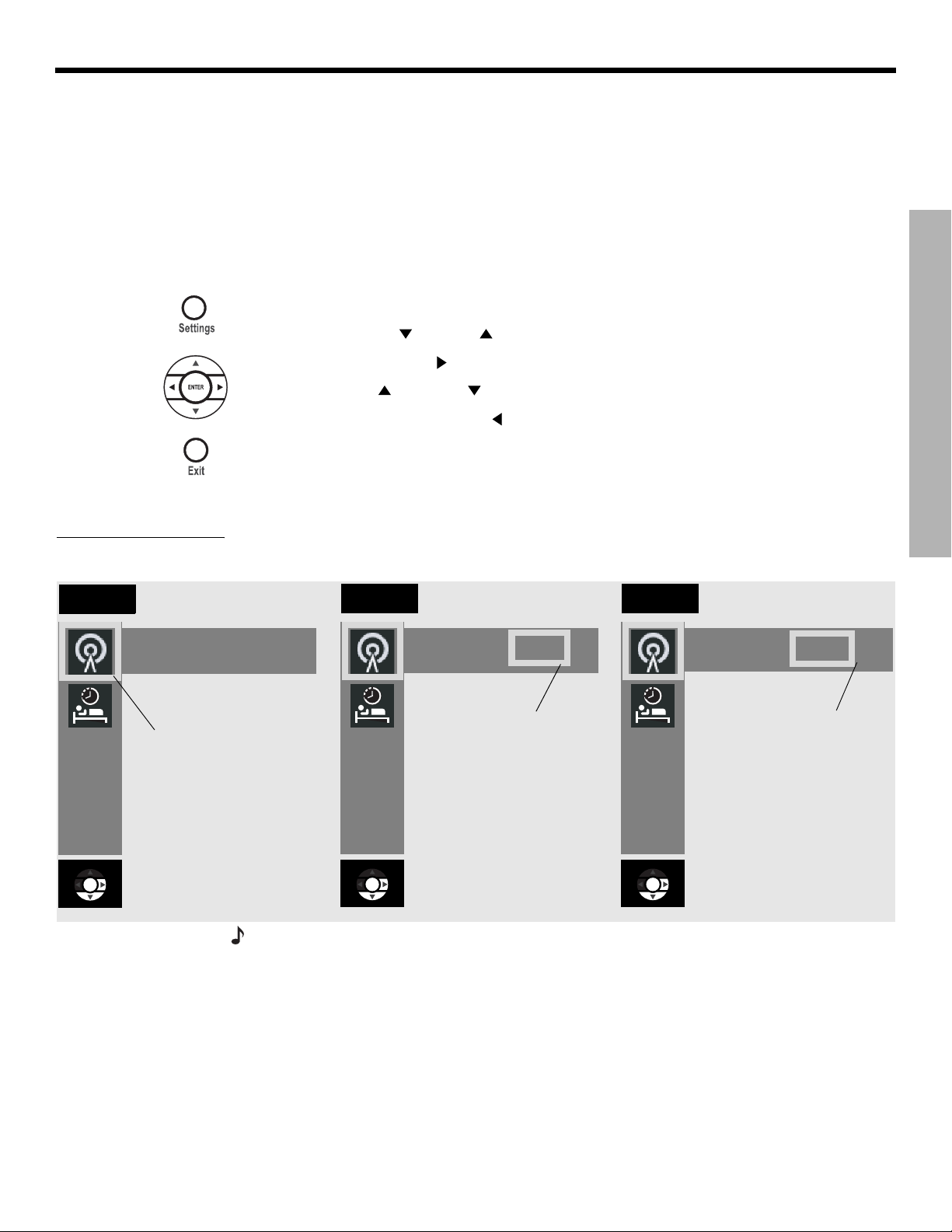
Dansk Italiano SvenskaDeutsch NederlandsEnglish FrançaisEspañol
CHANGING SOURCE SETTINGS
To make changes in the settings menus
Whether you use your TV screen or the media center display to change settings, the same
instructions apply.
You can use the actions above to change back to the original (default) settings, too. Do that if
you do not like the effect of a change you have made, or accidentally made a change you did
not intend. The default settings for each source are shown in the menu tables on the following
pages.
1.
Turn on your TV and select the correct TV input to view your 3•2•1 system.
2. Press a source button on your 3•2•1 remote control.
3. Press Settings to display the Settings menu for the selected source.
CHANGING SOURCE SETTINGS
Figure 26
Changing the FM Output
Mode setting
Tuner
Ouput Mode: Auto
The down arrow
button was pressed
to select the
OUTPUT MODE
menu item.
4. Using the down (
5. Press the right arrow (
6. Press the up (
7. Press Enter or the left arrow (
) and up ( ) arrow buttons, select the menu item you want to change.
) button to select the menu item setting.
) or down ( ) arrow button to change the setting.
) button to save the setting.
8. Press Exit to dismiss the Settings menu.
The progression in Figure 26 shows Output Mode for the FM tuner being changed from Auto
to Stereo.
Tuner
Output Mode: Auto
The right arrow
button was
pressed to select
the setting.
Tuner
Output Mode: Stereo
The up or down
arrow button
was pressed to
change setting
from Auto to
Stereo.
Note: You can restore all default settings by choosing Restore Settings in the Systems menu,
under Media Center options. This reverts all source settings back to the factory default settings. It also changes the Audio Processing setting back to Automatic (found in the Systems
menu under Audio options).
41
Page 42

CHANGING SOURCE SETTINGS
FM/AM settings menu
To see the FM/AM Settings menu, press FM-AM on the remote. Then press Settings. Press
Exit to remove the menu from the screen.
DanskItalianoSvenska DeutschNederlands EnglishFrançais Español
CHANGING SOURCE SETTINGS
CD settings menu
Item
To see the CD Settings menu, press CD-DVD on the remote while playing an audio CD. Then
press Settings. Press Exit to remove the menu from the screen.
Item
Name Settings Default Description
Output Mode
(FM only)
RDS Info
(FM only, and
only on some
systems)
Sleep Timer Off, 10-90
Name Settings Default Description
Track __ of __ Allows you to select a track on the
Auto, Stereo,
Mono
Off, On Off Displays station and program infor-
minutes
Auto Allows you to listen to stereo broad-
casts in either stereo or mono output.
mation (as available from Radio Data
System).
Off Turns the system off after the set time
expires. Choose off to deactivate the
timer.
current disc.
Sleep Timer Off, 10-90
minutes
Off Turns the system off after the set time
expires. Choose off to deactivate the
timer.
42
Page 43

Dansk Italiano SvenskaDeutsch NederlandsEnglish FrançaisEspañol
DVD settings menu
To see the DVD Settings menu, press CD-DVD on the remote while playing a DVD video disc.
Then press Settings. Press Exit to remove the menu from the screen.
CHANGING SOURCE SETTINGS
Item
Name Settings Default Description
Movie EQ* On, Off On Optimizes the tonal balance for movies.
Range Compression* On, Off On Adjusts volume to maintain dialogue intelligibility. Keeps
some sounds from overwhelming others.
Mono Decoding* On, Off On Engages Videostage® 5 mono decoding circuitry to pro-
cess mono sound (one-channel audio) for your system.
Time _:_ _ 0:00 Displays the elapsed time of the current DVD. Also,
allows you to move to a new location in the movie by
entering a new time.
Title __ of __ Selects a DVD title from the current disc, according to
the number set. Some DVDs do not allow direct access
to titles.
Chapter _____ Selects a DVD chapter from the current DVD movie,
according to the number entered. Some DVDs do not
allow direct access to chapters.
Audio Track Dependent on
disc
Subtitle language Dependent on
disc
Allows you to choose one of the available audio tracks
on the current disc.
Allows you to choose one of the available subtitle languages (only if included on disc).
CHANGING SOURCE SETTINGS
Camera Angle 1 of ____ Allows you to select one of the available camera angles
(only if included on disc).
A-B Repeat A, B Repeats a segment of the DVD after the start and end
points are defined. To begin:
1. Move backward or forward to the point in the DVD
where you want the segment to start.
2. Press Enter.
3. Move to the point where you want it to end.
4. Press Enter.
Repeats until you press the Settings button.
Sleep Timer Off, 10-90
minutes
*Available only when Audio Processing is set to User Adjustable. See “Audio options” on
page 47 for more information.
Off Turns the system off after the set time expires. Choose
off to deactivate the timer.
43
Page 44

CHANGING SOURCE SETTINGS
TV, CBLSAT, and AUX settings menu
The settings below affect programs on the TV, even when the source of the program is VCR,
CBLSAT or AUX. There are no separate setting menus for these sources.
Movie EQ, Range Compression and Mono Decoding appear in the menu only if Audio
Processing is set to User Adjustable. Audio Processing can be found in the System
menu under Audio options.
DanskItalianoSvenska DeutschNederlands EnglishFrançais Español
CHANGING SOURCE SETTINGS
Item
*Available only when Audio Processing is set to User Adjustable. See “Audio options” on
page 47 for more information.
** Available only when a Dolby Digital 1+1 signal is detected.
Name Settings Default Description
Movie EQ* On, Off On Optimizes the tonal balance for
movies.
Range
Compression*
Mono Decoding* On, Off On Engages Videostage® 5 mono decod-
Dolby Digital
1+1**
Sleep Timer Off, 10-90
On, Off On Adjusts volume to maintain dialogue
intelligibility. Keeps some sounds from
overwhelming others.
ing circuitry to process mono sound
(one-channel audio) for your system.
1, 2, Both 1 Plays audio content of selected
soundtrack(s).
The content of the second sound-
track may be a second language, for
example.
Off Turns the system off after the set time
minutes
expires. Choose off to deactivate the
timer.
44
Page 45

Dansk Italiano SvenskaDeutsch NederlandsEnglish FrançaisEspañol
Using the System menu
Changes to system options are typically made only once. If your system operates as you
want it to, there may be no need for any changes. In some cases, however, changes are
required to make the system fully compatible with the installation options you have chosen.
To view the System menu
Unlike the source settings menus, the System menu only appears on your TV screen.
1. Turn on your TV and select the correct TV input to view your 3•2•1 system.
2. Press the System button on your 3•2•1 remote control. The System menu appears with
Audio options selected, showing a list of the Audio options that can be changed.
3. Press Exit to dismiss the System menu.
Note:
Entering the System menu causes any DVD or VCD that is playing to pause.
CHANGING SYSTEM OPTIONS
CHANGING SYSTEM OPTIONS
Figure 27
Sample system menu
showing audio options
List of system options for
the selected category
Navigation help – Which remote
control buttons to use
Categories of options
$XGLR
9LGHR
0HGLD
&HQWHU
5HPRWH
&RQWURO
6HOHFW$XGLRWRDGMXVWWKHVHV\VWHPRSWLRQV
%DVV&RPSHQVDWLRQ
7UHEOH&RPSHQVDWLRQ
$XGLR3URFHVVLQJ
,QSXW/HYHOV
navigate
select
'9'
/RFN
45
Page 46

CHANGING SYSTEM OPTIONS
DanskItalianoSvenska DeutschNederlands EnglishFrançais Español
To change system options
Changing system options in this menu is similar to changing the settings for a source.
1.
Turn on your TV and select the correct TV input to view your 3•2•1 system.
2. Press the System button on your 3•2•1 remote control.
CHANGING SYSTEM OPTIONS
3. Using the right (
(Audio, Video, Media Center, Remote Control, or DVD Lock).
4. Press Enter or the down (
5. Using the down (
6. Press the right arrow (
7. Press the up (
8. Press Enter or the left arrow ( ) button to save the setting.
9. Press Exit to dismiss the System menu.
) and left ( ) arrow buttons, highlight one of the option categories
) arrow to select the option category.
) and up ( ) arrow buttons, select the system option to change.
) button to see the system option settings.
) or down ( ) arrow button to change the setting.
46
Page 47

Dansk Italiano SvenskaDeutsch NederlandsEnglish FrançaisEspañol
Audio options
Figure 28
Audio system options
CHANGING SYSTEM OPTIONS
The audio options affect the way the system sounds in your home.
Note:
Listening to an audio source while you change audio options can be helpful. Some
changes will be immediately noticeable and therefore useful in fine tuning your selections.
$XGLR
6HOHFW$XGLRWRDGMXVWWKHVHV\VWHPRSWLRQV
%DVV&RPSHQVDWLRQ
7UHEOH&RPSHQVDWLRQ
$XGLR3URFHVVLQJ
,QSXW/HYHOV
9LGHR
0HGLD
&HQWHU
5HPRWH
&RQWURO
'9'
/RFN
CHANGING SYSTEM OPTIONS
navigate
select
System Option Settings Description
Bass Compensation 0 [default]
–14 to +14
Treble Compensation 0 [default]
–14 to +14
Audio Processing Automatic [default]
User Adjustable
Normal low-frequency reproduction.
Decreased (–) or increased (+) low-frequency reproduction.
Normal high-frequency reproduction.
Decreased (–) or increased (+) high-frequency reproduction.
Standard Bose
Processing options (Movie EQ, Range Compression, Mono
Decoding) available in Source Settings menus.
Input Levels:
TV Analog Input Level
TV Digital Input Level
Normal [default]
–6, –3, +3, +6
Standard signal level (loudness).
Decreases or increases signal level (adjustable to match the
levels of other audio devices).
CBLSAT Analog Input Level
CBLSAT Digital Input Level
AUX Analog Input Level
Note: You may want to adjust the input levels of external audio
devices so they match the system’s internal FM and CD levels.
AUX Digital Input Level
®
processing applied.
47
Page 48

CHANGING SYSTEM OPTIONS
Video options
Figure 29
Video system options
The video options affect the way the picture looks on your TV.
$XGLR
6HOHFW9LGHRWRDGMXVWWKHVHV\VWHPRSWLRQV
79$VSHFW5DWLR
:LGHVFUHHQ'9'V
9LGHR&RQQHFWRU
9LGHR%ODFN/HYHO
799LGHR)RUPDW
3URJUHVVLYH6FDQ
9LGHR
0HGLD
&HQWHU
5HPRWH
&RQWURO
'9'
/RFN
DanskItalianoSvenska DeutschNederlands EnglishFrançais Español
navigate
navigate
select
select
CHANGING SYSTEM OPTIONS
System Option Settings Description
TV Aspect Ratio Normal [default]
Widescreen
Widescreen DVDs Modified [default]
Unmodified
Video Connector Composite + S-Video [default]
Component
Video Black Level Normal [default]
Extended
TV Video Format NTSC (US) [default]
PAL (EU R OP E )
(MULTISTANDARD)
Progressive Scan* Off [default]
On
4:3 ratio screen display.
16:9 ratio widescreen display.
Modified [default].
Unmodified.
A read-only line that identifies the type of video connection
made on the back panel of the media center.
Screen black level generally appropriate for TVs.
Increases screen black level, appropriate for certain TVs.
Correct for NTSC (US standard) monitors.
Correct for PAL (European standard) monitors.
Only for a TV that supports multiple formats (NTSC and PAL).
Screen image repaints in standard style.
Screen image repaints in advanced style (if available on the TV).
*Appears only when your TV is connected to the media center using a component video
connection.
48
Page 49

Dansk Italiano SvenskaDeutsch NederlandsEnglish FrançaisEspañol
Media center options
The media center options affect the general operation of the system.
Figure 30
Media Center system
options
0HGLD
$XGLR
6HOHFW0HGLD&HQWHUWRDGMXVWWKHVHV\VWHPRSWLRQV
'LVSOD\%ULJKWQHVV
'LVSOD\/DQJXDJH
2SWLFDO6RXUFH
7XQHU6SDFLQJ
%RVHOLQN5RRP&RGH
5HVWRUH6HWWLQJV
9LGHR
&HQWHU
5HPRWH
&RQWURO
'9'
/RFN
CHANGING SYSTEM OPTIONS
CHANGING SYSTEM OPTIONS
navigate
select
System Option Settings Description
Display Brightness 4 [default]
1 (darkest) to 4 (brightest)
Display Language English [default]
Media center display lights with a mid-range brightness.
Darkens or lightens the media center display.
On-screen display menus appear in the selected language.
Dansk, Deutsch, Espanol, Francais,
Italiano, Nederlands, Svenska
Optical Source None [default]
TV, CBLSAT, AUX
Tuner Spacing US [default]
European
®
Bose
link Room
Code*
B [default], C, D, E, F, G, H, I, J, K,
L, M, N, or O
Restore Settings No
Yes
No digital signal received via optical cable.
Digital signal received via optical cable for selected source.
Channel spacing for AM/FM radio stations set to selected
region standard.
Assigns a room code to your 3•2•1 Series II system when
it is connected to a Bose link source.
Maintains current system settings.
Reverts system settings back to factory defaults.
*Appears only when a Bose link source is connected.
49
Page 50

CHANGING SYSTEM OPTIONS
Remote control options
The Remote Control options help you set up your remote to control other audio devices that
are connected to your system.
Figure 31
Remote Control system
options
$XGLR
6HOHFW5HPRWH&RQWUROWRDGMXVWWKHVHV\VWHP
RSWLRQV
9LGHR
0HGLD
&HQWHU
5HPRWH
&RQWURO
DanskItalianoSvenska DeutschNederlands EnglishFrançais Español
'9'
/RFN
$8;'HYLFH
$8;%UDQG
$8;'HYLFH&RGH
CHANGING SYSTEM OPTIONS
79%UDQG
79'HYLFH&RGH
6$7'HYLFH
&%/
6$7%UDQG
&%/
&%/6$7'HYLFH&RGH
navigate
select
System Option Settings Description
TV Brand Brand name Provides a list of TV brands for the 3•2•1 remote control to operate.
TV Device Code Code number Provides a list of available device codes for the selected TV brand.
CBLSAT Device Cable, Cable/DVR,
Identifies the device connected to the CBLSAT input.
Satellite, Satellite/
DVR, HDTV tuner
CBLSAT Brand Brand name Provides a list of cable/satellite box brands for the 3•2•1 remote
control to operate.
CBLSAT Device Code Code number Provides a list of available device codes for the selected cable/satellite
box brand.
AUX Device TV/DVD, DVD/DVR,
Identifies the device connected to the AUX input.
DVD/DVD recorder,
Satellite/DVR,
Cable/DVR, DVR,
VCR
AUX Brand Brand name Provides a list of video recorder brands for the 3•2•1 remote control to
operate.
AUX Device Code Code number Provides a list of available device codes for the selected AUX device or
(or video recorder) brand.
Note:
To find the brand and device codes for each component that can be connected to, and
controlled by the 3•2•1 system, see “Device Codes on page A-1.”
Note:
After programming your remote to control external audio/video devices from the System
menu, press the System button once to continue navigating the System menu.
50
Page 51

Dansk Italiano SvenskaDeutsch NederlandsEnglish FrançaisEspañol
DVD Lock options
Figure 32
DVD Lock system options
CHANGING SYSTEM OPTIONS
The DVD Lock options allow you to restrict viewing of DVD videos with certain ratings. To
activate this feature, you need to set a level of restriction and establish a password in the
DVD Lock section of the System menu.
$XGLR
6HOHFW5HPRWH&RQWUROWRDGMXVWWKHVHV\VWHP
RSWLRQV
/RFN8QUDWHG'LVFV
/RFN'LVFV5DWHG$ERYH
0DQDJH'9'3DVVZRUG
9LGHR
0HGLD
&HQWHU
5HPRWH
&RQWURO
'9'
/RFN
CHANGING SYSTEM OPTIONS
navigate
select
System Option Settings Description
Lock Unrated Discs Off
On
No restriction applies to unrated DVD movies.
Restricts viewing access to unrated titles when
password is set.
Lock Discs Rated Above 1 to 8 Helps prevent viewing discs above the selected
number when a password is created.
Manage DVD Password _ _ _ _ Establishes a new four-number code to restrict
access to movies with certain ratings.
Setting a password and restriction level
Your password will help prevent unauthorized viewing of DVD videos that have a higher rating
than your restriction level. There are 8 levels to choose from, matched to movie ratings set by
the Motion Picture Association of America (MPAA). See “Motion Picture Association of America (MPAA) rating system” on page 52.
1.
Turn on your TV and select the correct TV input to view your 3•2•1 system.
2. Press the System button on your 3•2•1 remote control.
3. Using the right (
4. Press Enter or the down (
If you are using the DVD Lock option for the first time, enter a four-digit password. Then
Note:
) and left ( ) arrow buttons, highlight the DVD Lock option.
) arrow key.
enter it again to confirm.
51
Page 52

CHANGING SYSTEM OPTIONS
Enter your four-digit password.
5.
6. Using the down ( ) button, scroll down to Lock Discs Rated Above.
7. Press the right arrow ( ) button to see the available settings.
DanskItalianoSvenska DeutschNederlands EnglishFrançais Español
CHANGING SYSTEM OPTIONS
8. Press the up (
9. Press Enter or the left arrow (
10. Press Exit to dismiss the Settings menu.
) or down ( ) arrow button to find the rating you want.
) button to save the setting.
Motion Picture Association of America (MPAA) rating system
Parental
Control
Setting
8 None
7 NC-17 Adult audiences
6 R Mature audiences
5 Mature teenage audiences
4 PG-13 Teenage audiences
3 PG Mature young audiences
2 Most audiences
1 G General
MPAA
Rating
Audience
Restriction
Example: Choosing a Parental Control Setting of 4, restricts access to videos
rated above PG-13. Videos with ratings above that may be viewed only after entering
the password.
Your password also helps prevent others from changing the restriction level setting without
permission.
52
Page 53

Dansk Italiano SvenskaDeutsch NederlandsEnglish FrançaisEspañol
Cleaning
MAINTAINING YOUR SYSTEM
Cleaning the media center
• Use only a soft, dry cloth to clean the outside surfaces of the media center.
• Do not use any sprays near the system. Do not use any solvents, chemicals, or cleaning
solutions containing alcohol, ammonia, or abrasives.
• Do not allow liquids to spill into any openings.
Figure 33
Disc care
Cleaning the speakers
• Clean the surface of your speakers with a soft, damp cloth. You can use an ammonia-free
window cleaner on a soft cloth to maintain the finish.
• Do not use any sprays near the speakers. Do not use any solvents, chemicals, or cleaning
solutions containing alcohol, ammonia, or abrasives.
• Do not allow liquids to spill into any openings.
• The speaker grilles require no special care, although you may vacuum them carefully
if necessary.
Cleaning discs
• Handle discs by their edges to prevent fingerprints and scratches (Figure 33a).
• To remove stains or fingerprints from the surface of a disc, use a soft and dry lint-free,
cloth. Wipe in straight movements from the center of the disc to the outside (Figure 33b).
Do not use any chemical products; they can damage the disc.
• Do not use a circular motion to clean (Figure 33c).
• Do not write on or attach labels to the surface of a disc.
• To minimize exposure to dust and dirt, return discs to their cases after use. Store each disc
in its case, away from direct sunlight, high temperatures, and humidity.
a.
b. c.
MAINTAINING YOUR SYSTEM
53
Page 54

MAINTAINING YOUR SYSTEM
Replacing the remote control batteries
CAUTION: Please dispose of used batteries properly, following any local regulations.
Do not incinerate.
• Slide open the battery compartment (Figure 34).
• Notice the polarity markings (+ and –) inside the compartment and install the batteries
accordingly. Be sure to replace both batteries.
• Slide the battery compartment cover back into place.
DanskItalianoSvenska DeutschNederlands EnglishFrançais Español
Figure 34
Putting in the batteries
Accessories
MAINTAINING YOUR SYSTEM
Figure 35
Speaker accessories
AA batteries (IEC R6)
Battery compartment cover
The Bose® 3•2•1 Series II and 3•2•1 GS Series II system shelf speakers are compatible with
Bose mounting accessories, including the UB-20 wall brackets, UFS-20 floor stands and
UTS-20 table stands (Figure 35). Bose also offers cable adapters for use in running speaker
cable through walls.
For further information or to order the mounting brackets, stands, or cable adapters, contact
your Bose dealer or Bose Corporation directly. Refer to the address sheet included in the
shipping carton.
UFS-20
UB-20
Wall Bracket
US-T20
Tab l e S t an d
Floor Stand
54
Page 55

Dansk Italiano SvenskaDeutsch NederlandsEnglish FrançaisEspañol
Troubleshooting table
Problem What to do
TROUBLESHOOTING
System doesn’t do
anything
Disc won’t eject • Turn off the unit.
No sound • Increase the volume.
• Make sure the unit is turned on. Try pressing the remote On-Off button and the media
center On-Off button.
• Make sure the power cord is inserted securely into the Acoustimass
firmly into an operating AC wall outlet.
• Be sure to select a source (CD/DVD, AM/FM, etc.).
• Unplug the Acoustimass module power cord from the outlet for one minute, then reconnect it. This allows the unit to reset itself. After reconnecting the power cord, wait for the
message, “BOSE 3•2•1” to appear on the media center display.
• Unplug the Acoustimass module power cord from the outlet for one minute, then reconnect it. This allows the unit to reset itself.
• Before powering on, press and hold Eject on the media center.
• Check to see if MUTE is lit on the display. If it is, press the Mute button on the remote control to unmute the sound.
• Be sure to select the correct source for the desired input.
• Make sure the Acoustimass module cable and speaker cable are firmly seated in their
respective jacks and the multi-pin connector on the other end is firmly seated in the
Acoustimass module jack.
• Check speaker connections.
• Turn the media center off for 10 seconds, then on again, to restore communication
between the media center and the speakers.
• Check the connections for any external audio devices.
• Be sure the disc is placed correctly, label-side up, in the CD tray.
• Connect the FM and AM antennas.
• Unplug the Acoustimass module power cord from the outlet for a minute, then reconnect it.
This allows the unit to reset itself.
• If you are using an optical digital audio connection, make sure that the optical jack is correctly assigned in the System menu.
• Make sure the volume is turned up on the TV.
• Check input level settings for each connected device in the System menu.
®
module and plugged
TROUBLESHOOTING
55
Page 56

TROUBLESHOOTING
Problem What to do
Sound, but no picture • Make sure the TV is on.
• When playing a DVD or other video source, make sure the TV is set to the correct video
input.
DanskItalianoSvenska DeutschNederlands EnglishFrançais Español
Remote control is
inconsistent or does not
work
Radio does not work
or has poor reception
DVD or CD does not
play
TROUBLESHOOTING
FM sound is distorted • Adjust antenna position to reduce interference.
Sound is distorted • Make sure speaker cables are not damaged and the connections are secure.
• Check batteries and their polarity (+ and –). See “Replacing the remote control batteries”
on page 54.
• Point the remote control at the media center.
• Make sure antennas are connected properly.
• Move AM antenna at least 20 inches (50 cm) from the media center.
• Adjust antenna position to improve reception.
• AM antenna must be upright.
• Move antennas farther from TV or other electronic equipment.
• You may be in an area of weak signal coverage.
• Check to see if the Play symbol in the display is lit.
• After pressing the CD/DVD button, wait a few seconds before pressing Play.
• Make sure the disc is properly inserted (label-side up).
• Eject the disc and try loading it again.
• There may be dirt or dust on the disc. Clean the disc. See “Cleaning discs” on page 53.
• The disc may be defective. Try another disc.
• Make sure region codes for both the DVD and player match. See “Check for region code
compatibility” page 6.
• Reduce the output level from any external audio devices connected to the music center.
• Reduce the input level setting for the connected device in the system menu.
Picture is black and
white or rolling
You forgot your
password
Customer service
• Check the video cable connections.
• Check the Video Format setting and change to appropriate setting (NTSC or PAL).
See “Video options” on page 47.
• Enter the password 2673 to access the parental controls and create a new password.
For additional help in solving problems, contact Bose® Customer Service. Refer to the
address list included in the carton.
56
Page 57

Dansk Italiano SvenskaDeutsch NederlandsEnglish FrançaisEspañol
TECHNICAL INFORMATION
Power rating
USA/Canada: 120V 60Hz 300W
International: 220-240V
Dual voltage: 115/230V
50/60Hz 300W
50/60Hz 300W
Audio inputs
AUX – Left, Right (analog); D (digital)
CBLSAT – L, R (analog); D (digital)
TV – L, R (analog); D (digital)
Optical – SPDIF digital, mapped to input
Audio outputs
Acoustimass® Module – SPDIF
Video inputs
C (composite) – NTSC or PAL format
S-Video
Video outputs
C (composite) – NTSC or PAL format
S-Video
Component Y, Pb, Pr
Antennas
FM 75: – external FM antenna
AM – external AM antenna
Maximum ambient temperature
104°F (45°C)
Dimensions
Media center: 3¼"H x 13¾"W x 10"D
(8.3 cm x 34.9 cm x 25.4 cm)
Remote control: 1
3•2•1 speakers: 3
3•2•1 GS speakers: 2
Acoustimass module: 14
1
/8"H x 21/2"W x 9"D
(3.0 cm x 6.5 cm x 22.9 cm)
1
/2"H x 77/8"W x 51/4"D
(8.7 cm x 19.9 cm x 13.6 cm)
1
/2"H x 51/2"W x 4"D
(6.4 cm x 14 cm x 10.5 cm)
1
/2"H x 83/4"W x 191/8"D
(36.7 cm x 22.2 cm x 48.5 cm)
Weights
Media center: 6.7 lb (3.0 kg)
3•2•1 speakers: 2.7 lb (1.2 kg) each
GS speakers: 1 lb (.45 kg) each
Acoustimass module: 23.3 lb (10.6 kg)
Finish
Media center: polymer
Speakers: polymer
Acoustimass module: polymer
57
Page 58

DEVICE CODES
Finding the right device codes
Using the right device codes, you can set up your new universal remote to control the video devices you want to use
with your speaker system. For the remote setup procedure, see your owner’s guide.
To find available codes for a device, search the listing under the appropriate device type heading.
If you have a combination device, such as a TV with a built-in DVD or VCR device, first search the “COMBINATION”
listings starting on page 20. If you cannot find a valid code there, then search the listings for individual device types.
Keep in mind that combination devices may use the same code for each device in the unit.
TV ........................................................................................................................ A-2
Television
CBL...................................................................................................................... A-8
Cable box
SAT ...................................................................................................................... A-9
Satellite receiver
DVD ................................................................................................................... A-11
VCR ................................................................................................................... A-15
VCR
DVR ................................................................................................................... A-18
Digital Video Recorder
HDTV ................................................................................................................. A-19
HDTV Decoder
Combination ...................................................................................................... A-20
TV/VCR .............................................................................................................. A-20
TV/VCR combination
TV/DVD .............................................................................................................. A-20
TV/DVD combination
TV/VCR/DVD ........................................................................................................ A-20
TV/VCR/DVD combination
VCR/DVD ............................................................................................................ A-20
VCR/DVD combination
CBL/DVR ............................................................................................................ A-21
Cable/DVR combination
SAT/DVR............................................................................................................. A-21
Satellite
/DVR combination
DVD/DVR ............................................................................................................ A-21
DVD
/DVR combination
A–1
Page 59

D
EVICE CODES
TV
Television
A-Mark .......................... 0003
Abex .............................. 0032
Addison ......................... 0092, 0108, 0653, 1150
Admiral .......................... 0093, 0463
Advent ........................... 0761, 0783, 0815, 0817,
Adventura...................... 0046
Adyson .......................... 0032, 0217
AEA ............................... 0037
AEG ............................... 0606
Agashi ........................... 0217
Aiko ............................... 0037, 0092, 0217
Aim ................................ 0208, 0606, 0706
Aiwa............................... 0701, 1180
Akai ............................... 1537, 0812, 0745, 0714,
Akiba ............................. 0037, 0282
Akira .............................. 0037, 0556
Akito .............................. 0037
Akura ............................. 0037, 0282, 0714, 1037
Alaron ............................ 0179
Alba ............................... 0037, 0443, 0714, 1037
Albatron......................... 0700, 0843
Alfide ............................. 0672
Allorgan ......................... 0217
Allstar ............................ 0037
Ambassador.................. 0177
America Action.............. 0180
Amplivision.................... 0217, 0370
Ampro............................ 0751
Amstrad......................... 0037, 0171, 0177, 1037
Anam ............................. 0003, 0180, 0250, 0628,
Anam National............... 0055, 0250, 0650
Andersson ..................... 1163
Anex .............................. 0037
Anhua ............................ 0051
Anitech .......................... 0037, 0282
Ansonic ......................... 0370, 0556
AOC............................... 0003, 0018, 0019, 0030,
Apex .............................. 0156, 0765
Apex Digital ................... 0748, 0765, 0767, 0879,
Arcam............................ 0217
Archer............................ 0003
0842
0708, 0706, 0702, 0698,
0672, 0631, 0606, 0602,
0556, 0548, 0480, 0217,
0208, 0178, 0060, 0037,
0030
0700
0052, 0060, 0092, 0093,
0108, 0178, 0179, 0180,
0185, 0451, 0628, 1150
0890
Ardem............................ 0037, 0486, 0556, 0633,
Aristona ......................... 0037, 0556
ART................................ 1037
Astra .............................. 0037
Asuka............................. 0217
ATD................................ 0698
Atlantic .......................... 0001
Audinac ......................... 0180
Audiosonic..................... 0037, 0217, 0370, 0486,
Audioton........................ 0217, 0486
Audiovox ....................... 0003, 0092, 0180, 0451,
Autovox ......................... 0217
Aventura ........................ 0171
Awa................................ 0037, 0108, 0157, 0217,
Axxon ............................ 0714
Baile............................... 0001, 0661
Baird.............................. 0208, 0217
Bang & Olufsen ............. 0565
Baosheng ...................... 0817
Basic Line...................... 0037, 0217, 0282, 0556,
Baur............................... 0037, 0146, 0512
Baysonic........................ 0180
Bazin.............................. 0217
Beaumark ...................... 0178
Beijing............................ 0001, 0208, 0226, 0661,
Beko .............................. 0037, 0370, 0486, 0606,
Belcor ............................ 0019
Bell & Howell ................. 0016, 0154
BenQ ............................. 1032, 1756
Beon .............................. 0032, 0037
Best ............................... 0370
Bestar ............................ 0037, 0370
Binatone ........................ 0217
Black Diamond.............. 0556, 0587, 1037
Blaupunkt ...................... 0170, 0195
Blue Sky ........................ 0037, 0282, 0556, 0606,
Blue Star........................ 0282
Boots............................. 0217
Boxlight ......................... 0893
BPL................................ 0037, 0208, 0282
Bradford ........................ 0180
Brandt 0335, 0560, 0625, 0714
Brandt Electronique....... 0335
Brinkmann ..................... 0037, 0486
Britannia ........................ 0217
Brockwood.................... 0019
0714
0714
0623, 0802, 0875
0512, 0606, 0698
1037, 1163
0812, 0817
0714, 1037
0714, 1037, 1254
Broksonic ...................... 0003, 0180, 0236, 0463
Bush .............................. 0037, 0208, 0217, 0282,
Caihong ......................... 0817
Cailing............................ 0748
Candle ........................... 0030, 0046, 0056, 0186
Carad............................. 0037, 1037
Carena ........................... 0037
Carnivale........................ 0030
Carver............................ 0054, 0170
Cascade ........................ 0037
Casio ............................. 0037
Cathay ........................... 0037
CCE ............................... 0037, 0217
Celebrity ........................ 0000
Celera ............................ 0765
Celestial......................... 0767
Centrex.......................... 0698, 0780
Centrum......................... 1037
Centurion....................... 0037
CGE ............................... 0370
CGM .............................. 1037
Changcheng .................. 0001, 0051, 0661, 0817
Changfei ........................ 0817
Changfeng..................... 0817
Changhai ....................... 0817
Changhong.................... 0156, 0508, 0765, 0767,
Chengdu........................ 0817
Ching Tai ........................ 0003, 0092, 0179
Chun Yun ....................... 0000, 0003, 0092, 0179,
Chung Hsin.................... 0053, 0108, 0180, 1150
Chunsun ........................ 0817
Cinema .......................... 0672
Cineral ........................... 0092, 0451
Citizen............................ 0030, 0039, 0046, 0056,
Clairtone ........................ 0185
Clarion ........................... 0180
Clarivox.......................... 0037
Clatronic ........................ 0037, 0217, 0370, 0556,
Clayton .......................... 1037
CMS Hightec ................. 0217
Commercial ..................
Solutions
Concerto........................ 0056
Condor........................... 0037, 0282, 0370
Conia ............................. 0754
Conic ............................. 0032
Conrac........................... 0808
0486, 0556, 0661, 0698,
0714, 1037
0783, 0817, 1156
0180, 0700, 0843, 1150
0060, 0092, 0186, 0280
0606, 0714
0047, 1447
TV
A–2
Page 60

D
EVICE CODES
Conrowa........................ 0145, 0156, 0698, 1156
Contec........................... 0037, 0157, 0180, 0185,
Cosmel .......................... 0037
TV
Craig.............................. 0180
Crosley .......................... 0054
Crown............................ 0037, 0039, 0053, 0180,
Crown Mustang............. 0672
Curtis Mathes................ 1347, 1147, 0702, 0466,
CXC............................... 0180
D-Vision......................... 0037, 0556
D.Boss........................... 0037
Daewoo ......................... 1661, 1150, 0880, 0865,
Dansai ........................... 0032, 0037, 0208
Dantax........................... 0606, 0714
Datsura.......................... 0208
Daytek ........................... 0037, 0706
Daytron.......................... 0019
Dayu .............................. 0661
De Graaf ........................ 0208, 0548
DEC ............................... 0556, 0698
Decca ............................ 0037, 0217
Deitron........................... 0037
Dell ................................ 1080, 1178, 1264, 1454
Denon............................ 0145, 0511
Denstar.......................... 0628
Denver........................... 0037, 0587, 0606, 1189
Desmet.......................... 0037
Diamant......................... 0037
Diamond........................ 0037, 0672, 0698, 0706
Dick Smith ....................
Electronics
Digatron......................... 0037
Digital Life ..................... 0780, 0872
Digitor............................ 0037, 0698
Digix .............................. 0880
DiK................................. 0037
Dixi ................................ 0037
DL.................................. 0037, 0780, 0872
Domeos......................... 0037, 1037
Dream Vision................. 1704
DSE ............................... 0698
Dual ............................... 0037, 0217
Dual Tec......................... 0217
Dumont ......................... 0017, 0019
0698
0208, 0370, 0486, 0606,
0672, 0714
0451, 0166, 0154, 0145,
0093, 0060, 0056, 0054,
0051, 0047, 0039, 0030,
0016
0706, 0700, 0672, 0661,
0634, 0628, 0623, 0556,
0451, 0217, 0180, 0178,
0170, 0154, 0108, 0092,
0056, 0039, 0037, 0032,
0030, 0019, 0003
0698
Durabrand ..................... 0003, 0171, 0178, 0180,
Dwin .............................. 0093, 0720, 0774
Dynatron........................ 0037
Ecco .............................. 0706
ECE ............................... 0037
Elbe ............................... 0217
Electroband ................... 0000, 0185
Electrograph.................. 1755
Electrohome .................. 0381
Elekta............................. 0037, 0282
Elektra ........................... 0017, 1661
Elin................................. 0037, 0548
Emerson ........................ 0714, 0623, 0486, 0463,
Emperor......................... 0282
Envision......................... 0030, 0813
Epson ............................ 0833, 0840, 1122, 1322
Erres .............................. 0037
ESA................................ 0171, 0812
ESC ............................... 0037, 0217
Ether .............................. 0003, 0030
Etron.............................. 0001
Eurofeel ......................... 0217
EuroLine ........................ 0556
Euroman ........................ 0037, 0217
Europa........................... 0037
Europhon....................... 0217
Evolution........................ 1756
Exquisit.......................... 0037
Fagor ............................. 0037
Feilu............................... 0817
Feiyue............................ 0817
Ferguson ....................... 0037, 0053, 0335, 0443,
Fidelity ........................... 0037, 0171, 0512
Filsai .............................. 0217
Finlandia........................ 0208, 0548
Finlux............................. 0037, 0179, 0217, 0480,
Firstar ............................ 0236
Firstline.......................... 0037, 0208, 0217, 0556,
Fisher............................. 0047, 0154, 0157, 0159,
Flint................................ 0037
Formenti ........................ 0037
Fortress ......................... 0093
Fraba ............................. 0037, 0370
Friac............................... 0037, 0370
Frontech ........................ 0217
0463, 1034, 1463
0451, 0370, 0282, 0280,
0236, 0185, 0180, 0179,
0178, 0177, 0171, 0154,
0039, 0038, 0037, 0019
0548, 0560, 0625
0556, 0606, 0629, 0631,
0714, 0808
0587, 0714, 0808, 1037
0208, 0217, 0370
Fujitsu............................ 0037, 0179, 0186, 0217,
Fujitsu General .............. 0217, 0683
Funai.............................. 0171, 0179, 0180, 0556,
Furi................................. 0145, 0817
Future ............................ 0037
Futuretech ..................... 0180
Galaxi............................. 0037
Galaxis........................... 0037, 0370
Ganxin ........................... 0817
Gateway ........................ 1755, 1756
GE.................................. 1454, 1447, 1347, 1147,
GEC ............................... 0037, 0217
General .......................... 0186
Genesis.......................... 0037
Gericom......................... 0808, 0865
Giant .............................. 0217
Gibralter......................... 0017, 0019, 0030
Gintai ............................. 1150
Go Video........................ 0886
GoldStar ........................ 0001, 0019, 0030, 0032,
Goodmans..................... 0032, 0037, 0179, 0217,
Gorenje.......................... 0037, 0370
Gradiente....................... 0053, 0056, 0170
Graetz............................ 0037, 0714
Granada......................... 0037, 0108, 0146, 0208,
Grandin.......................... 0037, 0282, 0714, 1037
Grundig.......................... 0037, 0195, 0370, 0443,
Grunpy........................... 0179, 0180
H&B ............................... 0808
Haaz .............................. 0706
Haier .............................. 0037, 0508, 0587, 0698,
Haiyan............................ 0817
Halifax............................ 0217
Hallmark ........................ 0178
Hammerstein ................. 0060
Hampton........................ 0217
Hankook ........................ 0019, 0030, 0056, 0178,
Hanseatic....................... 0037, 0195, 0217, 0282,
Hantarex ........................ 0037, 0865
Hantor............................ 0037
0683, 0809, 0853, 1181
1271
0625, 0560, 0451, 0335,
0282, 0180, 0178, 0135,
0093, 0092, 0055, 0051,
0047, 0030, 0027, 0021
0037, 0039, 0056, 0154,
0178, 0217, 0556, 0606,
0714, 1150
0335, 0360, 0451, 0480,
0556, 0560, 0634, 0661,
0714, 0808, 1037, 1163
0217, 0226, 0548, 0560
0556, 0587, 0672, 0683,
0706
0768, 1034
0180, 0628
0556, 0634, 0661, 0714,
0808
A–3
Page 61

D
EVICE CODES
Harley Davidson............ 0179
Harman/Kardon............. 0054
Harsper.......................... 0865
Harvard.......................... 0180
Harwood........................ 0032, 0037
Havermy........................ 0093
HCM .............................. 0037, 0217, 0282, 0606
Helios ............................ 0865
Hello Kitty...................... 0451
Hema............................. 0217
Hher............................... 0714
Himitsu .......................... 0180, 0628
Hinari ............................. 0037, 0179
Hisawa........................... 0282, 0714
Hisense ......................... 0037, 0145, 0156, 0208,
Hitachi ........................... 0217, 0381, 0480, 0481,
Hitachi Fujian................. 0037, 0108, 0145, 0150
Home Electronics.......... 0606
Hongmei........................ 0093, 0817
Hongyan........................ 0817
Hornyphon .................... 0037
Hoshai ........................... 0282
Hua Tun ......................... 1150
Huafa............................. 0145
Huanghe........................ 0817
Huangshan.................... 0817
Huanyu.......................... 0817
Huari.............................. 0145
Hugoson........................ 0890
Huodateji....................... 0051
Hyper............................. 0217
Hypson.......................... 0037, 0282, 0714, 1037
Hyundai ......................... 0037, 0698, 0706, 0849,
Iberia ............................. 0037
ICE................................. 0217, 0556
Imperial.......................... 0037, 0370
Imperial Crown.............. 0001, 0661
Indiana........................... 0037
Infinity............................ 0054
Ingelen........................... 0714
Inno Hit.......................... 0037, 0217, 0282
Innova............................ 0037
Innowert ........................ 0865
Inteq .............................. 0017
0508, 0512, 0556, 0706,
0748, 0780, 1156
0508, 0512, 0548, 0578,
0629, 0634, 0719, 1037,
1045, 1145, 1150, 1156,
1225, 1245, 1256, 0016,
0019, 0027, 0030, 0032,
0037, 0038, 0039, 0056,
0092, 0108, 0145, 0151,
0156, 0157, 0165, 0178,
0179, 0186
0865
Interbuy ......................... 0037, 0512
Interfunk ........................ 0037, 0512
Internal .......................... 0037
Intervision...................... 0037, 0217, 0282, 0370,
IR ................................... 0032, 0037, 0093, 0108,
IRT ................................. 0451, 0628, 0698, 1661
Isukai ............................. 0037, 0282
ITC................................. 0217
ITT ................................. 0179, 0208, 0480, 0548
ITT Nokia ....................... 0179, 0208, 0480, 0548,
ITV ................................. 0037
Janeil ............................. 0046
JBL ................................ 0054
JCB................................ 0000
Jean............................... 0003, 0051, 0092, 0156,
Jensen........................... 0698, 0706, 0761, 0815,
Jiahua............................ 0051
Jinfeng........................... 0051, 0208, 0226, 0817
Jinque............................ 0817
Jinxing ........................... 0037, 0054, 0145, 0156,
JMB ............................... 0443, 0556, 0634
JNL................................ 0698
Jubilee ........................... 0556
Juhua............................. 0817
JVC................................ 0053, 0093, 0463, 0508,
Kaige ............................. 0817
Kaisui............................. 0037, 0217, 0282
Kambrook...................... 0217, 0556
Kangli ............................ 0001, 0661, 0817
Karcher.......................... 0037, 0282, 0606, 0714
Kathrein ......................... 0556
Kaypani ......................... 0052
KEC ............................... 0180
Kendo............................ 0037, 0512
Kennex .......................... 1037
Kenwood ....................... 0019, 0030
KIC................................. 0217
Kiota .............................. 0001
Kioto .............................. 0054, 0556, 0706
Kiton .............................. 0037
KLH ............................... 0765, 0767
KLL ................................ 0037
Kloss.............................. 0024, 0046
Kneissel......................... 0037, 0556
Kolin .............................. 0053, 0108, 0150, 0180,
0486
0146, 0157, 0195, 0217,
0226, 0370, 0512, 0556
0606
0179, 0236
0817
0556, 0698, 0817
0606, 0653, 0683, 0731,
1172, 1253
1150
Kongque ........................ 0817
Konka ............................ 0037, 0282, 0587, 0628,
Korpel ............................ 0037
KTV................................ 0030, 0039, 0180, 0185,
Kunlun ........................... 0051, 0208, 0226, 0661,
Kyoshu........................... 0032
Kyoto ............................. 0032, 0217
L&S Electronic............... 0714, 0808
LaSAT ............................ 0486
Lecson........................... 0037
Lemair............................ 0032
Lenco............................. 0037, 1037
Levis Austria.................. 0037
Leyco............................. 0037
LG.................................. 1265, 1178, 0856, 0714,
Liesenk & Tter................ 0037
Liesenkotter................... 0037
Lifetec............................ 0037, 0714, 1037
Lihua.............................. 0817
Lloyd’s ........................... 0001
Lloytron.......................... 0032
Loewe............................ 0037, 0136, 0512, 0633,
Logik.............................. 0001, 0016, 0060, 0698,
Longjiang....................... 0817
Luma.............................. 1037
Lumatron ....................... 0217
Lux May......................... 0037, 0556
Luxman.......................... 0056
Luxor ............................. 0179, 0208, 0217, 0480,
LXI ................................. 0047, 0054, 0154, 0156,
M & S............................. 0054
M Electronic................... 0037, 0217, 0480
Madison......................... 0037
Magnavox...................... 0020, 0024, 0030, 0037,
Magnum ........................ 0037, 0606, 0714
Majestic ......................... 0016
Manesth......................... 0037, 0217
Manhattan ..................... 0037, 1037
Marantz.......................... 0030, 0037, 0054, 0556,
Mark .............................. 0037, 0217, 0486, 0714
Masuda.......................... 0037, 0217
0632, 0638, 0703, 0707,
0714, 0754, 0817
0217, 0280
0817
0700, 0698, 0644, 0606,
0556, 0442, 0178, 0108,
0060, 0056, 0039, 0038,
0037, 0032, 0030, 0019,
0003, 0001
0790
0706, 0880
0548, 0631, 1037, 1163
0178
0054, 0096, 0179, 0186,
0187, 0386, 0706, 0780,
0802, 1198, 1254, 1454
0704, 0854, 0855, 1154,
1454
TV
A–4
Page 62

D
EVICE CODES
Materin .......................... 0208
Matsui............................ 0037, 0177, 0195, 0208,
TV
Matsushita..................... 0051, 0250, 0650
Matsuviama................... 0587
Maxent .......................... 1755
Mediator ........................ 0037
Medion .......................... 0037, 0512, 0556, 0698,
Megapower ................... 0700
Megatron....................... 0003, 0145, 0178
MEI ................................ 0185, 1037
Meile.............................. 0817
Melectronic.................... 0037, 0195, 0217, 0480,
Memorex ....................... 0016, 0056, 0060, 0150,
Mercury ......................... 0001, 0060, 0556, 0706
Mermaid ........................ 0037
Metronic ........................ 0625
Metz .............................. 0037, 0388, 0447, 0587,
MGA .............................. 0019, 0030, 0037, 0150,
Micromaxx..................... 0037, 0808, 1037
Microstar ....................... 0808
MicroTEK....................... 0706
Midland ......................... 0017, 0032, 0039, 0047,
Minato ........................... 0037
Minerva.......................... 0108
Minutz............................ 0021
Mitsubishi...................... 1250, 1182, 1171, 1150,
Mivar ............................. 0217, 0370, 0609
Monivision ..................... 0700, 0843
Morgan’s ....................... 0037
Motorola........................ 0055, 0093
MTC............................... 0019, 0030, 0056, 0060,
MTEC ............................ 0032
MTlogic ......................... 0714
Mudan ........................... 0051, 0208, 0226, 0817
Multitec ......................... 0037, 0486, 1037
Multitech ....................... 0037, 0180, 0217, 0486,
Murphy .......................... 0039
Musikland...................... 0037
Myryad .......................... 0556
NAD............................... 0156, 0178, 0866
Naiko ............................. 0037, 0606
0217, 0335, 0443, 0556,
0629, 0714, 1037
0714, 0808, 0880, 1037,
1248
0512, 0634, 0661, 0714
0154, 0178, 0179, 0250,
0463, 1037
0746
0178
0051, 0135
1037, 0868, 0836, 0817,
0556, 0512, 0381, 0250,
0236, 0208, 0180, 0179,
0178, 0154, 0150, 0108,
0093, 0056, 0037, 0030,
0019
0185, 0370, 0512
0556
Nansheng ...................... 0817
NAT................................ 0226
National ......................... 0051, 0055, 0208, 0226,
NEC ............................... 1704, 1182, 1150, 0882,
Neckermann .................. 0037, 0370, 0512, 0556
NEI................................. 0037
Neovia ........................... 0865
Nesco ............................ 0179
Netsat............................ 0037
NetTV............................. 1755
Network......................... 0032
Neufunk......................... 0037, 0556, 0714
New Tech....................... 0217
Newave.......................... 0092, 0093, 0178, 1150
Nikkai............................. 0032, 0037, 0217
Nikko ............................. 0030, 0092, 0178
Noblex ........................... 0154, 0180
Nokia ............................. 0179, 0208, 0480, 0548,
Norcent.......................... 0748, 0824
Nordic............................ 0217
Nordmende ................... 0037, 0195, 0335, 0560,
Normerel........................ 0037
Noshi ............................. 0018
Novak ............................ 0037
Novatronic..................... 0037
NTC ............................... 0092
Nu-Tec........................... 0037, 0698, 0706
Oceanic ......................... 0208, 0548
Okano............................ 0037, 0370
Omni.............................. 0698, 0706, 0780, 0872
Onimax .......................... 0714
Onking........................... 0280
Onwa ............................. 0180, 0602
Optimus......................... 0154, 0166, 0250, 0650
Optoma ......................... 0887
Optonica........................ 0093, 0165
Orion.............................. 0037, 0177, 0179, 0236,
Orline............................. 0037
Ormond ......................... 1037
Osaki ............................. 0032, 0037, 0217, 0556
Osume........................... 0032, 0037, 0157
Otto Versand ................. 0037, 0093, 0217, 0226,
Pacific............................ 0037, 0556, 0714, 1037
Palladium....................... 0037, 0370, 0714
0508
0817, 0704, 0661, 0603,
0508, 0497, 0381, 0217,
0186, 0178, 0170, 0165,
0156, 0154, 0056, 0053,
0051, 0046, 0030, 0019
0606, 0631
0714
0443, 0463, 0556, 0606,
0714, 0880, 1463
0512, 0556
Palsonic......................... 0001, 0037, 0217, 0698
Panama ......................... 0037, 0217
Panashiba...................... 0001
Panasonic...................... 1650, 1410, 1177, 1175,
Panavision ..................... 0037
Panda ............................ 0051, 0208, 0226, 0508,
Pathe Cinema................ 0370
Penney........................... 0003, 0018, 0019, 0021,
Perdio ............................ 0037, 0282
Phase............................. 0032
Philco............................. 1661, 0774, 0628, 0463,
Philex............................. 0548
Philips............................ 1756, 1454, 1154, 0774,
Phoenix.......................... 0037, 0486
Phonola ......................... 0037, 0080
Pilot ............................... 0019, 0030, 0037, 0039,
Pioneer .......................... 0037, 0038, 0166, 0170,
Pionier ........................... 0486
Playsonic ....................... 0037, 0217, 0714
Polaroid ......................... 0765, 0865, 1276
Polytron ......................... 0282
Portland ......................... 0019, 0039, 0092
Powerpoint .................... 0037
Premier .......................... 0037
Prima ............................. 0761, 0783, 0815, 0817
Princess......................... 0698
Princeton ....................... 0700, 0717
Prinston ......................... 1037
Prism ............................. 0051
Profex ............................ 0370
Profitronic...................... 0037
Proline............................ 0037, 0556, 0625, 0634
Proscan ......................... 0047, 1347, 1447
Prosonic ........................ 0037, 0217, 0451, 0714
Protech .......................... 0037, 0180, 0217, 0486,
Proton............................ 0001, 0003, 0030, 0039,
ProVision ....................... 0037, 0556, 0714
Pulsar............................. 0017, 0019
1168, 0853, 0650, 0548,
0508, 0250, 0226, 0208,
0108, 0055, 0054, 0051,
0037
0698, 0706, 0780, 0817
0027, 0030, 0032, 0039,
0047, 0051, 0056, 0060,
0135, 0156, 0178, 1347
0451, 0370, 0186, 0180,
0178, 0145, 0096, 0092,
0056, 0054, 0037, 0032,
0030, 0020, 0019
0690, 0556, 0512, 0187,
0186, 0178, 0108, 0092,
0080, 0056, 0054, 0051,
0037, 0032, 0030, 0027,
0024, 0020, 0019, 0017,
0000
0706
0486, 0512, 0679, 0760,
0866, 1260
1037
0052, 0056, 0178, 0466,
0644
A–5
Page 63

D
EVICE CODES
Pye ................................ 0037, 0556
Qingdao......................... 0051, 0208, 0226, 0817
Qualcraft........................ 0039
Quasar........................... 0051, 0055, 0165, 0250,
Quelle ............................ 0037, 0512, 1037
Questa........................... 0032
R-Line............................ 0037
Radiola .......................... 0037, 0217, 0556
Radiomarelli .................. 0037
RadioShack................... 0019, 0030, 0032, 0037,
Radiotone...................... 0037, 1037
Rank Arena.................... 0157, 0602
RCA............................... 1547, 1454, 1447, 1347,
Realistic......................... 0019, 0030, 0032, 0039,
Recor............................. 0037
Rediffusion .................... 0548
Reflex ............................ 0037, 1037
Relisys........................... 0865
Reoc.............................. 0714
Revox ............................ 0037
RFT ................................ 0037, 0370
Rhapsody ...................... 0185
Ricoh ............................. 0037
Rinex ............................. 0698
Roadstar........................ 0037, 0282, 0714, 1037,
Rowa ............................. 0037, 0217, 0556, 0587,
Royal Lux ...................... 0335
Runco............................ 0017, 0030, 0497, 0603
Ruyi ............................... 0817
Saba .............................. 0250, 0335, 0548, 0560,
Sagem 0830
Saige ............................. 0817
Saisho ........................... 0177, 0217, 0556
Saivod ........................... 0037, 1037
Salora ............................ 0208, 0480, 0548, 0606,
Salsa.............................. 0335
Sampo........................... 0030, 0032, 0039, 0052,
Samsung ....................... 1150, 1060, 0817, 0814,
0650, 0865
0039, 0047, 0056, 0154,
0165, 0178, 0180
1247, 1147, 1047, 0679,
0625, 0618, 0560, 0178,
0135, 0093, 0092, 0090,
0060, 0051, 0047, 0038,
0030, 0019, 0018, 0000
0056, 0154, 0165, 0178,
0180
1189
0698, 0748, 0817
0625, 0714
0631
0092, 0093, 0154, 0171,
0178, 0650, 0700, 1755
0812, 0774, 0766, 0718,
0702, 0682, 0644, 0618,
0587, 0556, 0370, 0226,
0019, 0030, 0032, 0037,
0039, 0056, 0060, 0090,
0092, 0093, 0154, 0156,
0178, 0179, 0195, 0208,
0217
Samsux ......................... 0039
Sandra........................... 0217
Sansei............................ 0451
Sansui............................ 0037, 0463, 0587, 0602,
Sanyo ............................ 1154, 1150, 1142, 0893,
Sanyuan ........................ 0093, 0817
SBR ............................... 0037, 0556
Schaub Lorenz .............. 0037, 0486, 0548, 0606,
Schneider ...................... 0037, 0217, 0556, 0714,
Scimitsu......................... 0019
Scotch ........................... 0178
Scott.............................. 0019, 0178, 0179, 0180,
Sears ............................. 0047, 0054, 0056, 0146,
Seaway.......................... 0556, 0634
Seelver........................... 1037
SEG ............................... 0037, 0217, 0634, 1037,
SEI ................................. 0177
Sei-Sinudyne................. 0037
Semivox......................... 0180
Semp............................. 0156, 1356
Serino ............................ 0093
Shancha ........................ 0817
Shanghai ....................... 0208, 0226, 0817
Shaofeng ....................... 0145, 0817
Sharp............................. 1193, 1165, 0851, 0818,
Shen Ying...................... 0003, 0092, 0179
Shencai.......................... 0145
Sheng Chia.................... 0093, 0179, 0236, 1150
Shenyang ...................... 0817
Shintoshi........................ 0037
Shivaki........................... 0037, 0178, 0443, 0451
Shogun.......................... 0019
Shorai ............................ 0179
Show ............................. 0706
Siemens......................... 0032, 0037, 0146, 0157,
Siesta............................. 0370
Signature ....................... 0016
Silva............................... 0037
Silva Schneider.............. 0037
Silver.............................. 0037, 0179
SilverCrest..................... 1037
0698, 0706, 0714, 1537
0799, 0798, 0556, 0508,
0486, 0381, 0370, 0280,
0217, 0208, 0180, 0159,
0157, 0156, 0154, 0146,
0145, 0108, 0088
0714
1037
0236
0154, 0156, 0159, 0171,
0178, 0179
1163
0787, 0720, 0689, 0688,
0650, 0491, 0386, 0165,
0157, 0093, 0053, 0039,
0032, 0030
0195
Simpson ........................ 0186, 0187
Singer ............................ 0335, 0548, 0698, 0706,
Sinotec .......................... 0706
Sinudyne........................ 0177
SKY................................ 0037, 0282
Skygiant......................... 0180
Skyworth ....................... 0037, 0698, 0748, 0817
Sliding............................ 0865
SLX ................................ 0512
Soemtron....................... 0865
Solavox.......................... 0032, 0037, 0548
Sole ............................... 0813
Soniko ........................... 0037
Sonitron......................... 0208, 0217, 0370
Sonoko .......................... 0037, 0282
Sonolor .......................... 0208, 0282, 0548
Sontec ........................... 0037, 0370
Sony .............................. 1651, 1505, 1300, 1167,
Soundesign ................... 0178, 0179, 0180, 0186
Soundwave.................... 0032, 0037
Sowa.............................. 0051, 0060, 0092, 0156,
Spectricon ..................... 0003
Squareview.................... 0171
Ssangyong..................... 0032
SSS................................ 0019, 0180
Stag ............................... 0032
Standard........................ 0037, 0217, 1037
Starlite ........................... 0037, 0180
Stenway......................... 0282
Strato............................. 0037
Studio Experience ......... 0843
Sunic Line...................... 0037
Sunkai............................ 0037
Sunstar .......................... 0037
Sunwood ....................... 0037
Superscan ..................... 0864
Supersonic .................... 0037, 0208, 0698, 1189
SuperTech ..................... 0037
Supra ............................. 0039, 0056, 0178
Supre-Macy................... 0046
Supreme ........................ 0000
Susumu ......................... 0335
SVA................................ 0587, 0698, 0748, 0768,
Sylvania ......................... 0020, 0030, 0054, 0096,
Symphonic .................... 0171, 0180
1537
1100, 1010, 0834, 0650,
0250, 0170, 0157, 0156,
0150, 0145, 0111, 0093,
0080, 0053, 0037, 0000
0178, 0226, 1150
0865, 0870, 0871, 0872
0171, 0381
TV
A–6
Page 64

D
EVICE CODES
Synco ............................ 0000, 0060, 0092, 0093,
Sysline........................... 0037
T+A................................ 0447
TV
Tacico ............................ 0092, 0178, 0179, 1150
Tai Yi.............................. 1150
Taishan .......................... 0817
Tandy............................. 0039, 0093, 0217
Targa.............................. 0702
Tashiko .......................... 0032, 0092, 0146, 0217,
Tatung............................ 0003, 0037, 0051, 0054,
TCL................................ 0698, 0706, 1537
TCM............................... 0714, 0808
Teac............................... 0037, 0170, 0171, 0178,
Tec................................. 0037, 0217
Tech Line ....................... 0037
Technics ........................ 0051, 0250, 0556, 0650
TechniSat....................... 0037, 0556
Technisson .................... 0714
Technol Ace................... 0179
Technosonic .................. 0556
Techview........................ 0847
Techwood...................... 0003, 0051, 0056, 1163
Tecnimagen ................... 0556
Teco............................... 0051, 0092, 0093, 0178,
Tedelex .......................... 0037, 0208, 0217, 0556,
Tek................................. 0706
Teknika .......................... 0016, 0019, 0039, 0054,
Telecor........................... 0037
Telefunken ..................... 0037, 0056, 0335, 0486,
Telefusion ...................... 0037
Telegazi ......................... 0037, 0556
Telesonic ....................... 0037
Telestar.......................... 0037, 0556
Teletech ......................... 0037, 1037
Teleton........................... 0186, 0217
Teleview......................... 0037
Tempest......................... 0037, 0556
Tennessee ..................... 0037
Tensai ............................ 0037, 0217, 0556, 1037
Tera................................ 0030, 0092, 0466
Tesla .............................. 0037
Tevion ............................ 0556, 0714, 0767, 1037,
0178, 0451
0650, 1150
0055, 0060, 0154, 0156,
0217, 0556, 0629, 1150,
1156, 1254, 1756
0217, 0282, 0512, 0556,
0698, 0706, 0714, 1037,
1755
0280, 0653
0606, 0706, 1537
0056, 0060, 0092, 0150,
0179, 0180, 0186
0560, 0587, 0625, 0698,
0702, 0706, 0714
1248
Texet.............................. 0217
ThemeScene ................. 0887
Thompson ..................... 0625
Thomson ....................... 0037, 0335, 0560, 0625,
Thorn ............................. 0037, 0335, 0512
Tiane.............................. 0093, 0817
TMK............................... 0056, 0177, 0178
TML ............................... 1756
TNCi .............................. 0017
Tobo............................... 0748
Tokai .............................. 0037, 1037
Tokaido.......................... 1037
Tomashi ......................... 0282
Tongtel........................... 0587, 0780
Tophouse....................... 0180
Toshiba .......................... 1704, 1656, 1508, 1356,
Tosonic .......................... 0185
Totevision ...................... 0039
Towada .......................... 0217
Toyoda........................... 0037
Trakton........................... 0217
Trans Continens ............ 0037, 0217, 1037
Transonic ....................... 0037, 0512, 0587, 0698,
Triad............................... 0037, 0556
Trical .............................. 0157
Triumph.......................... 0177, 0556
Tsoschi .......................... 0282
Tuntex............................ 0030, 0092
TVS................................ 0463
TVTEXT 95..................... 0556
Uher............................... 0037, 0480, 0486
Ultravox ......................... 0037
Unic Line ....................... 0037
United............................ 0037, 0606, 0714, 1037
Universal........................ 0027, 0037
Universum ..................... 0032, 0037, 0146, 0157,
Univox ........................... 0037
V2max ........................... 0865
V7 Videoseven............... 1755
V7Videoseven................ 0880
Vector Research............ 0030
Vestel............................. 0037, 0217, 0556, 1037,
Victor ............................. 0053, 0250, 0650, 0653
Videocon ....................... 0508
1447
1265, 1256, 1169, 1156,
1150, 0845, 0832, 0718,
0714, 0650, 0644, 0618,
0556, 0508, 0381, 0217,
0195, 0156, 0154, 0145,
0093, 0060
0780
0170, 0177, 0217, 0370,
0480, 0512, 0556, 0618,
0631, 1037
1163
Videotechnic.................. 0217
Vidikron.......................... 0054
Vidtech........................... 0019, 0178
Viewsonic ...................... 0857, 0864, 0885, 1755
Viking............................. 0046
VInc................................ 1756
Vision............................. 0032, 0037, 0217
Vistar.............................. 0548
Vizio ............................... 0864, 0885, 1756
Voxson........................... 0178
Waltham......................... 0037, 0217, 0443, 1037
Wards ............................ 1347, 1156, 1147, 0866,
Warumaia....................... 0661
Watson .......................... 0037, 1037
Waycon.......................... 0156
Wega.............................. 0037
Wegavox........................ 0037
Welltech......................... 0714
Weltblick........................ 0217
Westinghouse................ 0003, 0451, 0889, 0890
Weston........................... 0037
Wharfedale .................... 0037, 0556, 0706
White Westinghouse...... 0037, 0186, 0463, 0623
Windsor ......................... 1037
Windstar ........................ 0282
Windy Sam .................... 0556
Wintel............................. 0714
World-of-Vision.............. 0880, 0890
Xenius............................ 0634, 0661
Xiahua............................ 0698, 0817
Xihu................................ 0817
XLogic............................ 0698
XMS............................... 0698
Xrypton .......................... 0037
Yamaha.......................... 0019, 0030, 0650, 0769,
Yamishi .......................... 0217, 0282
Yapshe........................... 0250
Yokan............................. 0037
Yoko............................... 0037, 0217
Yoshita........................... 0706
Youlanasi ....................... 0817
Zenith............................. 0016, 0017, 0092, 0178,
Zenor ............................. 0208
Zonda ............................ 0003, 0698
0187, 0186, 0180, 0179,
0178, 0166, 0165, 0156,
0154, 0135, 0111, 0096,
0000, 0016, 0017, 0018,
0019, 0020, 0021, 0024,
0027, 0030, 0047, 0051,
0054, 0055, 0056, 0060,
0080
0833, 0839
0463, 1145
A–7
Page 65

D
EVICE CODES
CBL
Cable box
ABC............................... 0001, 0003, 0007, 0008,
ADB ............................... 1063, 1230, 1269
Aichi Denshi .................. 1512
Alcatel ........................... 0896
Allegro ........................... 0153, 0315
Americast ...................... 0899
Amstrad......................... 1222
Antronix......................... 0022, 0207
Archer............................ 0022, 0153, 0207, 0797
Auna .............................. 1230, 1269
Austar............................ 0012, 0276
Belcor............................ 0056
Bell & Howell ................. 0014
Bell South...................... 0899
Birmingham Cable.........
Communications
British Telecom .............. 0003
Cable & Wireless ........... 1068
Cable Star ..................... 0056
Cabletenna.................... 0022
Cableview...................... 0022
Century.......................... 0153
Citizen ........................... 0153, 0315
Clearmaster................... 0883
ClearMax....................... 0883
Colour Voice.................. 0025, 0031
Comcast........................ 1376
Comtronics.................... 0040
Contec........................... 0019
Coolmax........................ 0883
Daeryung....................... 0008, 0477, 0877, 1877
Digeo............................. 1187
Digi ................................ 0637
Director.......................... 0476
Dumont ......................... 0637
DX Antenna ................... 1500
Eastern .......................... 0002
Emerson ........................ 0797
Everquest ...................... 0015, 0040
Focus ............................ 0400
Foxtel ............................ 1222
France Telecom............. 0817, 0896
Freebox ......................... 1482
Fujitsu............................ 1497
Funai.............................. 0019
Galaxi ............................ 0008
0011, 0013, 0014, 0017,
0237
0276
Garrard .......................... 0153
GC Electronics .............. 0056, 0207
GE.................................. 0237
Gehua............................ 0476
Gemini ........................... 0015, 0797
General Instrument........ 0003, 0011, 0014, 0015,
GMI................................ 0015, 0797
Golden Channel............. 1063, 1110
GoldStar ........................ 0040, 0144
Goodmind ..................... 0797
Hamlin ........................... 0009, 0020, 0034, 0259,
Hitachi ........................... 0011, 0014
Hytex ............................. 0007
i3 Micro.......................... 1602
Jasco............................. 0015, 0153, 0315
Jebsee........................... 0400
Jerrold ........................... 0003, 0011, 0012, 0014,
KNC............................... 0008
Leon .............................. 0015
LG.................................. 0040, 0144
Linsay ............................ 0440
Macab ........................... 0817
Madritel ......................... 1230
Magnavox...................... 0014, 0027
Maspro .......................... 1510
Memorex ....................... 0000
MNET ............................ 0019
Motorola ........................ 0014, 0276, 0476, 0810,
Movie Time.................... 0063, 0156
Mr Zap........................... 1112
Mr. Zap .......................... 1112
MS ................................. 0015
Multichoice.................... 0019
Multitech........................ 0883
MultiVision..................... 0012
Myrio ............................. 1602
NEC ............................... 1496
Nokia ............................. 1569
Noos.............................. 0817, 1624
Novaplex ....................... 0618
NSC............................... 0063, 0156
NTL................................ 0003, 1060, 1068
Oak................................ 0007, 0019
Ono................................ 1068
Optimus......................... 0021
Optus............................. 0276, 1060
Pace .............................. 0008, 0237, 1060, 1068,
0276, 0476, 0810
0273
0015, 0276, 0476, 0810
1106, 1187, 1254, 1376,
1483
1577, 1877
Panasonic...................... 0000, 0008, 0021, 0040,
Panther .......................... 0637
Paragon ......................... 0000
Philips............................ 0013, 0025, 0027, 0031,
Pioneer .......................... 0144, 0533, 0877, 1021,
Popular Mechanics........ 0400
Pulsar............................. 0000
PVP Stereo ...................
Visual Matrix
Quasar ........................... 0000
Quiero............................ 0817
RadioShack ................... 0015, 0315, 0797, 0883
RCA ............................... 0021, 1256
Realistic......................... 0207
Recoton ......................... 0400
Regal ............................. 0020, 0259, 0273, 0279
Regency ........................ 0002
Rembrandt..................... 0011
Runco ............................ 0000
Sagem ........................... 0817, 1089, 1112
Salora ............................ 0000
Samsung ....................... 0000, 0040, 0144, 1060,
Satbox ........................... 0375
Scientific Atlanta............ 0008, 0017, 0237, 0477,
Seam ............................. 0510
Sejin............................... 1602
Signal............................. 0015, 0040
Signature ....................... 0011
SL Marx ......................... 0040
Sony .............................. 1006, 1460
Sprucer.......................... 0021
Starcom......................... 0003, 0014, 0015
Stargate......................... 0015, 0040, 0797
Starquest ....................... 0015
STS................................ 0156
Suena Madritel .............. 1230
Sumitomo ...................... 1500
Supercable .................... 0276
Supermax ...................... 0883
Sylvania ......................... 0001
Tadiran........................... 0040
Tandy ............................. 0258
Teleview......................... 0040
Telewest......................... 1068
Texscan ......................... 0001
TFC................................ 0310
Thomson........................ 1110, 1256
Time Warner .................. 1877
0107, 0375, 1488
0153, 0317, 0817, 1305
1500, 1877
0003
1666
0877, 1510, 1877
CBL
A–8
Page 66

D
EVICE CODES
Timeless ........................ 0040
Tocom............................ 0012, 0013
Torx................................ 0003
Toshiba.......................... 0000, 1509
Trans PX ........................ 0153, 0276, 0315
TransACT....................... 1106
Tri-Vision........................ 1257
Tristar............................. 0883
TS.................................. 0003
Tusa............................... 0015
CBLSAT
TV86 .............................. 0063
Unika ............................. 0022, 0153, 0207
United Artists................. 0007
United Cable ................. 0003
Universal ....................... 0022, 0056, 0153, 0191,
US Electronics............... 0276
V2 .................................. 0883
Viewmaster.................... 0883
Viewstar......................... 0027, 0063, 0258
Vision............................. 0883
Vortex View.................... 0883
Zenith ............................ 0000, 0008, 0525, 0899
Zentek ........................... 0400
0207
SAT
Satellite receiver
@sat............................... 1300
@Sky ............................. 1334
ABsat............................. 0713
ADB ............................... 1259, 1367, 1473, 1491
Aiwa............................... 1514
Akai ............................... 0200
Alba ............................... 0713
Allsat.............................. 0200, 1017, 1043
Alltech ........................... 0713
Allvision ......................... 1232, 1334, 1412
AlphaStar....................... 0772
Amino ............................ 1615
Amitronica ..................... 0713
Amstrad......................... 0713, 0795, 0847, 1175
Anglo ............................. 0713
Ankaro........................... 0713, 1279
AntSat ........................... 1017
Arcon............................. 1043, 1075, 1279
Arcus ............................. 1143
Arnion............................ 1300
Asat ............................... 0200
ASCI .............................. 1334
ASLF.............................. 0713
AssCom......................... 0853
Aston ............................. 1129, 1261
Astra .............................. 0713
Astro.............................. 0133, 0173, 0658, 1099,
Atsat .............................. 1300
AtSky............................. 1334
Audioline........................ 1429
Austar ............................ 1259
Axis................................ 1111
Bentley Walker .............. 1017
Black Diamond.............. 1284
Blaupunkt ...................... 0173
Blue Sky ........................ 0713
Boca .............................. 0713, 1232, 1366
Brainwave...................... 1294
British Sky .....................
Broadcasting
Broco............................. 0713
BskyB ............................ 0847, 1175
Bubu Sat ....................... 0713
Bush .............................. 1284, 1471
Canal Digital .................. 0853
Canal Satellite ............... 0853, 1339, 1853
Canal+ ........................... 0853
CanalSatellite ................ 0853, 1339
Centrex.......................... 1457
Century.......................... 0856
Chaparral....................... 0216
Chess ............................ 0713, 1334
CityCom ........................ 0299, 1075, 1176, 1232
CNS............................... 1367
Comag........................... 1169, 1232, 1366, 1412
Coship ........................... 1457
Crossdigital ................... 1109
Cyfra+............................ 1076
Cyrus ............................. 0200
D-box ............................ 0723, 0873
Daewoo ......................... 0713, 1111, 1296
Deltasat ......................... 1075
Dgtec............................. 1242
Digatron......................... 1294
Digena ........................... 1100
Digenius......................... 0299, 1161
Digipro........................... 1105
Digiturk .......................... 1076
DirecTV.......................... 1856, 1749, 1640, 1639,
1100
0847, 1175, 1847
1609, 1444, 1443, 1442,
1414, 1392, 1377, 1142,
1109, 1108, 1076, 0819,
0749, 0724, 0639, 0566,
0392, 0247, 0099
Dish Network.................
System
Dishpro .......................... 0775, 1005, 1505, 1775
Distratel ......................... 1283
Distrisat ......................... 0200
DMT............................... 1075
DNT ............................... 0200
Dream Multimedia ......... 1237, 1437, 1637
DX Antenna.................... 1530
Echostar ........................ 0167, 0280, 0610, 0713,
Einhell ............................ 0713
Elap................................ 0713, 1129
Elsat............................... 0713
Elta................................. 0200
eMTech .......................... 1214
Engel.............................. 0713, 1017
EuroLine ........................ 1251
Europhon....................... 0299
Eurosky.......................... 0299
Eutelsat.......................... 0713
Expressvu...................... 0775, 1775
Fenner ........................... 0713
Ferguson........................ 1291
Flair Mate....................... 0713
Fortec Star..................... 1017, 1293, 1550
Foxtel............................. 1176, 1356
Freecom ........................ 0173
FTEmaximal ................... 0713, 1449, 1556
Fuba .............................. 0173, 0299, 1161, 1214
Fugionkyo...................... 1105
Galaxis........................... 0853, 1111, 1557
Garnet............................ 1075
GbSAT ........................... 1214
GE.................................. 0392, 0566
Gecco ............................ 1273, 1412
General Instrument........ 0869
GF.................................. 1043
GF Star .......................... 1043
Globo............................. 1251
GOD Digital.................... 0200
GOI ................................ 0775, 1775
Goldbox......................... 0853
Golden Interstar............. 1283
Goldvision...................... 1017
Goodmans..................... 1246, 1284
Gradiente....................... 0099, 0856
Grundig.......................... 0173, 0750, 0847, 0853,
Hanseatic....................... 1099, 1100
0775, 1005, 1170, 1505,
1775
0775, 0853, 1005, 1169,
1170, 1200, 1323, 1409,
1467, 1477, 1505, 1775
1150, 1291, 1330, 1335
A–9
Page 67

D
EVICE CODES
Hauppauge.................... 1294
HB ................................. 1214
HDT ............................... 1159
Hirschmann................... 0173, 0299, 1111
Hisense ......................... 1535
Hitachi ........................... 0819, 1250, 1284, 1518,
Homecast...................... 1214
HTS ............................... 0775, 1775
Hughes.......................... 0749, 0819, 1442, 1749
Hughes Network ...........
Systems
Humax........................... 1176, 1427, 1568, 1648,
Huth............................... 1017, 1075
Hyundai ......................... 1075, 1159
iCan ............................... 1367
ID Digital........................ 1176
ILLUSION sat ................ 1557
iLo ................................. 1535
Imperial.......................... 1429
Innova............................ 0099
Interstar ......................... 1017, 1105, 1214
IR................................... 0173, 0282
Jaeger ........................... 1334
Jerrold ........................... 0869
JVC................................ 0775, 1170, 1507, 1531,
K-SAT ............................ 0713
Kamm............................ 0713
Kaon.............................. 1300
KaTelco.......................... 1111
Kathrein......................... 0173, 0200, 0249, 0658,
Kenwood ....................... 0853
Koscom......................... 1043, 1334, 1409
Kreiling .......................... 0249, 0658
Kreiselmeyer.................. 0173
L&S Electronic............... 1043, 1334
Labgear ......................... 1296
LaSAT ............................ 0173, 0299
Lenco ............................ 0713
Lenoxx........................... 1611
LG.................................. 1075, 1226, 1414
Lifesat............................ 0299, 0713, 1043
Lodos ............................ 1284
Logix.............................. 1017, 1075
Lorenzen........................ 0299, 1161, 1294
M vision......................... 1557
Magnavox...................... 0722, 0724
Manata .......................... 0713
Manhattan ..................... 1017
1523, 1525
0749, 1142, 1442, 1443,
1444, 1749
1670, 1675
1532, 1775
0713, 1057, 1221, 1416,
1561, 1567
Marantz ......................... 0200
Maspro .......................... 0173, 0713, 0750, 1520,
Mastec........................... 1334
Matsui............................ 0173, 1284
Maximum....................... 1075, 1334
Mediacom ..................... 1206
MediaSat ....................... 0853
Medion .......................... 0299, 0713, 1043, 1075,
Medison......................... 0713
Mega ............................. 0200
Memorex ....................... 0724
Metronic ........................ 0713, 1279, 1283, 1334
Metz............................... 0173
Micro ............................. 0713, 1294
Micro electronic............. 0713
Micromaxx..................... 0299
Microstar ....................... 1075
Microtec ........................ 0713
Mitsubishi ...................... 0749, 0819
Morgan’s........................ 0200, 0713, 1232
Motorola ........................ 0856, 0869
Myryad .......................... 0200
Mysat............................. 0713
NEC ............................... 1270, 1519
NEOTION....................... 1334
Netgem.......................... 1322
Netsat............................ 0099
Neuhaus ........................ 0713
Neuling .......................... 1232
Neusat ........................... 0713, 1279, 1334, 1409
Neveling......................... 1161
Next Level ..................... 0869
NextWave...................... 1017, 1143, 1551
Nikko ............................. 0200, 0713
Nokia ............................. 0723, 0751, 0853, 0873,
Nordmende ................... 1611
OctalTV.......................... 1294, 1505
Opentel.......................... 1232, 1412
Optex............................. 1043, 1283
Optus............................. 1143
Orbis.............................. 1334
Orbitech......................... 1099, 1100
Pace .............................. 0200, 0241, 0329, 0795,
Packard Bell .................. 1111
Palcom .......................... 0299, 1161
Panarex ......................... 1159
1530
1161, 1232, 1334, 1412
1023, 1223, 1311, 1312,
1723
0847, 0853, 1175, 1323,
1356, 1423, 1623
Panasonic...................... 0247, 0701, 0847, 1104,
Panda ............................ 0173
Pansat ........................... 1159, 1551
Paysat............................ 0724
Philips............................ 1749, 1442, 1142, 1118,
Phoenix.......................... 1273
Phonotrend.................... 1017, 1200
Pilotime.......................... 1339
Pino ............................... 1334
Pioneer .......................... 0329, 0352, 0853, 1308,
Preisner ......................... 1366
Premiere ........................ 0723, 0873, 1429
Prima ............................. 0795
Primacom ...................... 1111
Prod............................... 0639, 0723, 0873
Proscan ......................... 0392, 0566
Protek ............................ 1567
Proton............................ 1535
QNS............................... 1367, 1404
Quelle ............................ 0299
Radiola .......................... 0200
RadioShack ................... 0869
RCA ............................... 0143, 0392, 0566, 0855,
Realistic......................... 0052
Rebox ............................ 1214
Regal ............................. 1251
RFT ................................ 0200
Roadstar........................ 0713, 0853
Rover ............................. 0713
S-ZWO........................... 1207
SAB ............................... 1251
Sagem ........................... 0820, 1114, 1253, 1307,
Samsung ....................... 0853, 1017, 1108, 1109,
Sanyo ............................ 1219
Sat Control .................... 1300
Sat Cruiser..................... 1143
Sat Team........................ 0713
Satec ............................. 0713
Satelco .......................... 1232
Satplus .......................... 1100
Schaub Lorenz .............. 1214
Schneider ...................... 1206, 1251
Schwaiger...................... 1075, 1111, 1334, 1457
SCS ............................... 0299
1304, 1320, 1404, 1508,
1526
1114, 1076, 0856, 0853,
0819, 0750, 0749, 0724,
0722, 0200, 0173, 0133,
0099
1442
1291, 1392
1690
1206, 1243, 1244, 1276,
1293, 1343, 1377, 1442,
1458, 1570, 1609
SAT
A–10
Page 68

D
EVICE CODES
Sedea Electronique ....... 1105, 1206, 1283
SEG ............................... 1075, 1251
Serino ............................ 0610
Servi Sat........................ 0713
ServiSat......................... 1251
Sharp............................. 1489, 1517
Siemens ........................ 0173, 1657
Silva............................... 0299
Skantin .......................... 0713
SKR ............................... 0713
SKT................................ 1449
SKY ............................... 0099, 0847, 0856, 1175,
SKY Italia....................... 1847, 1848
Sky XL ........................... 1251, 1412
Sky+ .............................. 1175
Skymaster ..................... 0713, 1075, 1200, 1409,
SATDVD
Skymax ......................... 0200
Skyplus.......................... 1232, 1334, 1409, 1412
SkySat........................... 0713
Skyvision ....................... 1334
SL .................................. 0299, 1294
SM Electronic................ 0713, 1200, 1409
Smart............................. 0299, 0713, 1232, 1273
Sony .............................. 0282, 0639, 0847, 0853,
Star Choice ................... 0869
Starlite ........................... 0200
Stream........................... 1847, 1848
Strong............................ 0853, 1105, 1159, 1258,
Sunny ............................ 1300
Sunsat ........................... 0713
Supermax...................... 1143, 1283
TCL................................ 1143
Teac............................... 1251, 1322
TechniSat....................... 0200, 1099, 1100, 1195,
Technomate................... 1283
Technosat...................... 1143, 1206
Technotrend .................. 1429
Techsan ......................... 1017
Techwood 1284
tekComm....................... 1017
Teleciel........................... 1043
Teleka ............................ 0750
Telestar.......................... 1099, 1100, 1251, 1334
Telesystem .................... 1251
Televes .......................... 1214, 1300
Tempo ........................... 1143
Tevion ............................ 0713, 1334, 1409
1847, 1848, 1856
1611
1524, 1558, 1639, 1640
1300, 1409, 1430
1322
Thomson ....................... 0392, 0713, 0820, 0847,
Tivo................................ 1142, 1442, 1443, 1444
Tokai .............................. 0200
Tonna............................. 0713
Topfield.......................... 1206, 1207, 1545
Toshiba .......................... 0749, 0790, 0819, 1285,
TPS................................ 0820, 1253, 1307
Triax ............................... 0200, 0713, 0853, 1099,
Trio................................. 1075
TT-micro ........................ 1429
Turnsat........................... 0713
Twinner .......................... 0713
UltimateTV..................... 1392, 1640
Uniden ........................... 0052, 0722, 0724, 1521
Unimax .......................... 1457
Unisat ............................ 0200
United............................ 1251
Universum ..................... 0173, 0299, 1099, 1251
US Digital ...................... 1535
USDTV........................... 1535
Van Hunen..................... 1161
Variosat.......................... 0173
Ventana.......................... 0200
Vestel............................. 1251
Visionic .......................... 1105, 1206, 1279, 1283
Visiosat.......................... 0713, 1129, 1457
Voom ............................. 0869
Wintel ............................ 0299, 1161
Wisi................................ 0173, 0299
Wisplus.......................... 1258
Worldsat ........................ 1251, 1323
XMS............................... 1075
Xsat ............................... 0713, 0847, 1214, 1323
Xtreme ........................... 1300
Zehnder ......................... 1075, 1232, 1251, 1334,
Zenith ............................ 0856, 1856
0853, 1046, 1175, 1291,
1498, 1900
1446, 1501, 1516, 1530,
, 1749
1251, 1291, 1296
1412, 1413
DVD
DVD
3D Lab........................... 0539
A-Trend.......................... 0714
Acoustic Solutions ........ 0713, 0730, 1242
Adcom........................... 1094
Advent ........................... 1016
AEG ............................... 0770, 0788, 0790
AFK................................ 1051
Afreey ............................ 0698
Aim ................................ 0699, 0778, 0818, 0833,
Airis................................ 1005, 1224
Aiwa............................... 0533, 0641, 1633
Akai................................ 0690, 0705, 0766, 0770,
AKI................................. 1005
Akira .............................. 0699
Akura ............................. 0898, 1051, 1367
Alba ............................... 0539, 0672, 0695, 0699,
Albatros ......................... 1001
Alco ............................... 0790
Allegro ........................... 0869
Altacom ......................... 1224
Amitech ......................... 0770, 0784, 0850
Amphion ........................
Media Works
Amstrad......................... 0713
AMW.............................. 0872, 1176
Ansonic.......................... 0831
Apex .............................. 0672, 1061
Apex Digital ................... 0672, 0717, 0755, 0794,
Arianet ........................... 0770, 0818
Asono ............................ 1224
Aspire Digital ................. 1168, 1407
Atacom .......................... 1224
ATD ................................ 0718
Audiologic...................... 0736
Audiosonic..................... 0690, 1265
Audiovox........................ 0717, 0790, 1041, 1071,
Auvio.............................. 0843
Awa................................ 0730, 0872
Axion.............................. 0730, 1071, 1072
B & K ............................. 0655, 0662
Basic Line...................... 0713
Baze............................... 0898, 1165
BBK ............................... 1224
Bel Canto Design........... 1571
Bellagio.......................... 1004
Black Diamond .............. 0698, 0713, 0766, 0833,
Blaupunkt ...................... 0717
Blue Parade................... 0571
Blue Sky ........................ 0651, 0672, 0695, 0713,
Boghe ............................ 1004
Boman ........................... 0783
Brainwave...................... 0770, 1115
1165
0779, 0788, 0790, 0884,
0898, 0899, 1089, 1115
0713, 0717, 0730, 0783,
1051
0872, 1176
0796, 0797, 0830, 1004,
1020, 1056, 1061, 1100
1072, 1121, 1122
0884
0769, 0778, 0804, 0843
A–11
Page 69

D
EVICE CODES
Brandt ........................... 0503, 0551, 0651
Broksonic ...................... 0695, 0868
Bush .............................. 1695, 1165, 1128, 1051,
C-Tech........................... 0798
California ......................
Audio Labs
Cambridge Audio .......... 1109
Cambridge ....................
Soundworks
Cat................................. 0699, 1087
CAVS............................. 1057
CCE............................... 0730
Celestial......................... 1020
Centrex.......................... 0672, 1004
Centrum ........................ 0713, 0779, 1005
CGV............................... 1115
Changhong.................... 0627, 1061
Cinea ............................. 0831
Cinego........................... 1399
Cineral ........................... 0730
Cinetec .......................... 0713
cineULTRA..................... 0699
CineVision ..................... 0833, 0869, 0876, 1483
Citizen ........................... 1277
Classic........................... 0730, 1385, 1730
Clatronic........................ 0672, 0788, 0818, 1165
Clayton .......................... 0713
Coby.............................. 0730, 0770, 0778, 0852,
Codex............................ 1233
Compacks..................... 0826, 1265
Conia............................. 0516, 0672, 0798, 0852,
Continental Edison........ 0768, 0831
Craig.............................. 0831
Crown............................ 0690, 0769, 0770, 1115
Curtis Mathes................ 1087
Cybercom...................... 0831
CyberHome ................... 0714, 0816, 0874, 1023,
Cydectin........................ 1074
Cytron............................ 0651
D-Vision......................... 1115
Daenyx .......................... 0872
Daewoo ......................... 0705, 0714, 0770, 0784,
Daewoo .........................
International
Dalton............................ 1036
Dansai ........................... 0770, 0783, 1115
1021, 0884, 0879, 0833,
0831, 0778, 0758, 0730,
0717, 0713, 0699, 0695,
0690, 0676, 0672, 0516
0490
0690
1086, 1107, 1115, 1165,
1177, 1351
1004
1024, 1117, 1129
0832, 0833, 0869, 0870,
0872, 1169, 1172, 1234,
1242
0872
Dantax ........................... 0539, 0713, 0790, 1089,
Daytek ........................... 0872, 1005
Dayton........................... 0872
DCE ............................... 0831
DEC ............................... 0778, 0818
Decca ............................ 0770, 1115
Denon............................ 0490, 0634, 1282, 1634
Denver ........................... 0699, 0778, 0788, 0818,
Desav ............................ 0770
Desay ............................ 0800, 0843, 1407
Diamond........................ 0651, 0768, 0790
Dick Smith.....................
Electronics
Digihome ....................... 0713
digiRED ......................... 0717
Digitor............................ 0651, 0690, 1005
Digitrex .......................... 0672, 1056, 1100
DIGIXmedia ................... 0826
DiK................................. 0831
Dinamic ......................... 0788
Disney 0675, 1270
DiViDo............................ 0705
DK Digital ...................... 0831
DMTech ......................... 0783, 1271
Dragon........................... 0831
DSE ............................... 0833, 1483, 1730
DTS................................ 0799
Dual ............................... 0651, 0665, 0713, 0730,
Durabrand ..................... 0713, 0831, 1003, 1127
DVD2000 ....................... 0521
DVX................................ 0768
ECC ............................... 0730
Electrohome .................. 0770, 0784
Elfunk............................. 0850
Elin................................. 0770
Ellion.............................. 0850
Elta ................................ 0672, 0690, 0770, 0788,
Eltax............................... 0766
Emerson ........................ 0591, 0675, 0705, 0816,
Encore ........................... 0698
Enterprise ...................... 0591
Enzer ............................. 0665, 0766, 0770, 0784
EuroLine ........................ 0788, 1115
Fenner ........................... 0651, 0769
Ferguson ....................... 0651
Finlux............................. 0591, 0672, 0676, 0741,
1358
0898, 1107, 1165, 1353,
1359
0833, 1483, 1730
0779, 0783, 0790, 0831,
1068, 1085
0850, 1051, 1115
0821, 1268
0770, 0783, 1165
Fintec............................. 0784, 1169
Firstline .......................... 0651, 0713, 0799, 0843,
Fisher............................. 0670
Funai.............................. 0675, 0695, 1268, 1334
Gateway ........................ 1073, 1077, 1158
GE.................................. 0522, 0717, 0815
General Electric ............. 0717
Global Solutions ............ 0768
Go Video........................ 0715, 0741, 0744, 0783,
Go Vision ....................... 1071, 1072
GoldStar ........................ 0591, 0741
Goodmans..................... 0651, 0690, 0713, 0730,
GPX ............................... 0699, 0769
Gradiente....................... 0490, 0651
Graetz............................ 0665
Gran Prix........................ 0831, 0898
Grandin.......................... 0672, 0713, 1233
Greenhill ........................ 0717
Grundig.......................... 0539, 0551, 0651, 0670,
Grunkel .......................... 0770
GVG............................... 1169
H & B ............................. 0818, 0841, 0850, 1233
H&B ............................... 0713, 0818, 0841, 0850,
Haier .............................. 0843
Hanseatic....................... 0741, 0783
Harman/Kardon ............. 0582, 0702
HCM .............................. 0788
HDT ............................... 0705
Hen ................................ 0713
Hher............................... 0651, 0713, 0826, 0831,
HiMAX............................ 0843
Hisense.......................... 0718
Hitachi ........................... 0573, 0664, 0695, 0713,
Hiteker ........................... 0672, 0872
Home Electronics .......... 0730
Home Tech .................... 1107, 1224
Hoyo .............................. 0665
Humax ........................... 0646
Hyundai ......................... 0766, 0768, 0783, 0850
iLo.................................. 1348
Ingelen........................... 0788
Initial .............................. 0717, 0839
Integra ........................... 0571, 0627, 1634
IRT ................................. 0783
0869
0833, 0869, 1044, 1075,
1099, 1144, 1158, 1304,
1483, 1730
0783, 0790, 0833, 0879,
1004, 1730
0695, 0705, 0713, 0775,
0790, 1004, 1036, 1128,
1695, 1730
1233
1224
1247, 1664
DVD
A–12
Page 70

D
EVICE CODES
ISP................................. 0695
Jaton ............................. 0665, 1078
JBL ................................ 0702
JDV................................ 1367
Jeken............................. 0699
Jensen........................... 1016
Jindian........................... 0799
JMB............................... 0695
JNC ............................... 0672
JSI ................................. 1423
JVC................................ 0503, 0539, 0558, 0623,
jWin ............................... 1049, 1051
Karcher.......................... 0783
Kawasaki....................... 0790
Kendo............................ 0699, 0713, 0831
Kennex .......................... 0713, 0770, 0898
Kenwood ....................... 0490, 0534, 0682, 0737
Kiiro ............................... 0770
King DHome.................. 0799
Kingavon ....................... 0818
Kiss................................ 0665, 0841
KLH ............................... 0717, 0790, 1020, 1149,
DVD
KLH Digital .................... 0717
Koda.............................. 0818
Konka ............................ 0711, 0719, 0720, 0721
Koss .............................. 0651, 0896, 1423
Landel............................ 0826
Lasonic.......................... 0798, 1173
Lawson.......................... 0768
Lecson........................... 1533
Lenco ............................ 0651, 0699, 0713, 0770,
Lenoxx........................... 0690, 1127
Lexia.............................. 0699, 0768
LG.................................. 0591, 0741, 0790, 0801,
Lifetec............................ 0651, 0831
Limit .............................. 0768
LiteOn............................ 1058, 1158, 1416, 1440
Loewe............................ 0511, 0539, 0741, 0885
Logix.............................. 0705, 0783
Luker ............................. 1367
Lumatron....................... 0705, 0741, 0833, 1115
Lunatron........................ 0741
Luxman ......................... 0573
Luxor ............................. 0713, 1004, 1695, 1730
Magnasonic................... 0651, 0769
Magnavox...................... 0503, 0539, 0646, 0675,
Magnex ......................... 1165
0867, 1164, 1241, 1275
1261
0778, 0818, 1165
0869
0713, 0818, 0821
Malata............................ 0782, 1159
Manhattan ..................... 0705, 0713
Marantz ......................... 0539
Mark .............................. 0713
Marquant....................... 0770
Matsui............................ 0651, 0672, 0695, 0713,
Maxdorf ......................... 0788
Maxim............................ 0713, 0872
MBO .............................. 0690, 0730, 1730
McIntosh ....................... 1273, 1533
MDS .............................. 0778
Mecotek ........................ 0770
Medion .......................... 0630, 0651, 0758, 0770,
MEI ................................ 0790
Memorex ....................... 0690, 0695, 0831, 1270
Metronic ........................ 0690
Metz............................... 0525, 0571, 0713
Microboss...................... 0718
Micromaxx..................... 1695
Micromedia.................... 0503, 0539
Micromega .................... 0539
Microsoft ....................... 0522
Microstar ....................... 0831
Minato ........................... 0752
Minax............................. 0713
Minerva.......................... 0705
Minoka........................... 0770
Minowa.......................... 1165
Mintek............................ 0717, 0839
Mirror............................. 0752, 0879
Mitsubishi ...................... 0521, 0713, 1403, 1521
Mizuda........................... 0770, 0818
Momitsu ........................ 1082
Monyka.......................... 0665
MPX............................... 0843
MTlogic.......................... 1265
Mustek........................... 0730, 1730
Mx Onda........................ 0651
Myryad .......................... 0894
NAD ............................... 0591, 0692, 0741
Naiko ............................. 0770, 1004, 1367
Nakamichi...................... 1222
Narita............................. 1115
NEC ............................... 0591, 0692, 0785, 0869,
Neovia ........................... 1271
Nesa .............................. 0717
Neufunk......................... 0665
Nevir .............................. 0770, 0831
0884, 1004, 1695, 1730
0783, 0820, 0831, 0879
1404
NextBase....................... 0826
NexxTech....................... 1402
Nintaus .......................... 1051
Norcent.......................... 0872, 1003, 1107, 1265
Nordmende.................... 0831
Noriko ............................ 0752
Nowa ............................. 0843
Nu-Tec ........................... 0516
Okano ............................ 0752
Olidata ........................... 0672
Omni .............................. 0690, 0698, 0778, 0833
Onix ............................... 0672, 0852
Onkyo ............................ 0503, 0627, 0792, 1417,
Oopla............................. 1158
Oppo.............................. 1224
Optim............................. 0843
Optimus......................... 0525
OptoMedia.....................
Electronics
Orava ............................. 0818
Orion.............................. 0695, 1128, 1695
Oritron............................ 0651
Ormond 0713
Otic ................................ 0826
P&B................................ 0770, 0818
Pacific............................ 0695, 0713, 0768, 0790,
Packard Bell .................. 0770
Palladium....................... 0695, 0779
Palsonic......................... 0672, 0852
Panasonic...................... 0490, 0503, 0632, 0703,
Panda ............................ 0717
Paramount Pictures....... 0779
peeKTon ........................ 1224
Philco............................. 0690, 0788, 0790
Philips............................ 0503, 0539, 0646, 0675,
Phonotrend.................... 0672, 0699, 0818, 1165
PianoDisc ...................... 1024
Pioneer .......................... 0490, 0525, 0571, 0631,
Plu2 ............................... 0850
Pointer ........................... 0784
Polaroid ......................... 1020, 1061, 1086, 1200
Polk Audio ..................... 0539
Portland ......................... 0770
Powerpoint .................... 0872
Powtek........................... 0852
Prima ............................. 0766, 1016
Prima Electronic ............ 0766
1418, 1612
0896
0804, 0831
1010, 1011, 1282, 1362,
1462, 1490, 1762
0854, 0885, 1158, 1260,
1267, 1354, 1818
0632, 1571, 1816
A–13
Page 71

D
EVICE CODES
Princeton....................... 0674
Prinz .............................. 0831
Prism ............................. 0705
Proceed......................... 0672
Proline ........................... 0651, 0672, 0833, 1004
Proscan ......................... 0522
Proson........................... 0713
Prosonic ........................ 0752
ProVision ....................... 0699, 0778
Qwestar......................... 0651
Radionette..................... 0741, 0869
Raite .............................. 0665
RCA............................... 0522, 0571, 0717, 0769,
REALmagic.................... 0674
REC ............................... 0490, 0766
Recco ............................ 0698
Red Star ........................ 0770, 0788, 0898, 1003
Redstar.......................... 0898
Reoc.............................. 0752, 0768
Resonance .................... 0651
Revoy ............................ 0699, 0841
Rio ................................. 0869
RJTech .......................... 1360
Roadstar........................ 0690, 0699, 0713, 0730,
Ronin ............................. 0872
Rotel.............................. 0558, 0623, 1178
Rowa ............................. 0516, 0717, 0823, 0872,
Saba .............................. 0551, 0651, 0769
Sabaki ........................... 0798
Saivod ........................... 0831, 1367
Sakyno .......................... 0768
Salora ............................ 0741
Sampo........................... 0698, 0752
Samsung ....................... 0490, 0573, 0744, 0820,
Sansui ........................... 0695, 0768, 0784, 1695
Sanyo ............................ 0670, 0695, 0873
Scan .............................. 0705, 0850
ScanMagic .................... 0730
ScanSonic..................... 1695
Schaub Lorenz .............. 0770, 0788, 1115
Schneider ...................... 0539, 0651, 0705, 0713,
Schwaiger ..................... 0752
Scientific Labs............... 0768, 0798
Scott.............................. 0651, 0672, 0718, 0797,
Seeltech ........................ 1224
0790, 0822, 1022, 1132,
1193
0818, 0833, 0879, 0898,
1051, 1339
1004
0899, 1044, 1075, 1118
0779, 0783, 0788, 0790,
0804, 0831
1005, 1036
SEG ............................... 0665, 0713, 0768, 0798,
Semp............................. 0503
Sensory Science ........... 1158
Shanghai ....................... 0672
Sharp............................. 0630, 0675, 0713, 0752,
Sharper Image............... 1112, 1117
Sherwood...................... 0633, 0717, 0741, 0770,
Shinco ........................... 0717
Shinsonic....................... 0533, 0839
Sigma Designs .............. 0674
Sigmatek ....................... 1005
Siltex.............................. 1224
Silva............................... 0788, 0831, 0898
Silva Schneider.............. 0831, 0898
Simaudio ....................... 0885
Singer ............................ 0690, 0768
Skantic .......................... 0539, 0713, 1003
Skymaster ..................... 0730, 0768
Skysonic........................ 0766
Skyworth ....................... 0766, 0898
Slim Art.......................... 0784
Slim Devices.................. 0533
SM Electronic................ 0690, 0730, 0768
Smart............................. 0705, 0713, 0718
Sonai ............................. 0755
Sonashi.......................... 0831
Sonic Blue ..................... 0783, 0869, 1099
Sony .............................. 0533, 0573, 0772, 0864,
Soundmaster................. 0768
Soundmax ..................... 0768
Soundwave.................... 0783
Sova .............................. 1122
Spectra.......................... 0872
Standard........................ 0651, 0768, 0788, 0831
Star Cluster ................... 0768
Starlogic ........................ 1005
Starmedia...................... 0818, 1005, 1224
Strong............................ 0713
Sungale ......................... 1074
Sunkai............................ 0770, 0850
Sunstech ....................... 0831
Sunwood ....................... 0788, 0898
Superscan ..................... 0821
Supervision.................... 0768
SVA................................ 0672, 0717, 0860, 1105
Sylvania ......................... 0630, 0675, 0821, 1268
Symphonic .................... 0675, 1268
0872, 0884
1256
1043, 1077
1017, 1033, 1069, 1070,
1133, 1389, 1431, 1533,
1633
Synn .............................. 0768
TAG McLaren................. 0894
Tandberg........................ 0713
Tatung............................ 0770
Teac ............................... 0516, 0571, 0692, 0695,
Tec ................................. 0898
Technics......................... 0490, 0703
Technika ........................ 0768, 0770, 0831, 1115,
Technisson..................... 1115
Technosonic .................. 0730, 1051, 1115
Techwood ...................... 0692, 0713
Tedelex .......................... 0690, 0768, 1004
Telefunken ..................... 0758, 0770, 0788, 0790,
Teletech ......................... 0713, 0768
Telra ............................... 0676
Tensai ............................ 0651, 0690, 0770
Terapin........................... 1031
Tevion ............................ 0651, 0768, 0798, 0833,
Theta Digital .................. 0571
Thomson........................ 0522, 0551
Tivo................................ 1816
Tokai .............................. 0665, 0698, 0784, 0788,
Tokaido .......................... 0698
Toshiba .......................... 0503, 0695, 1045, 1154
TRANS-continents......... 0799, 0826, 0831, 0843,
Transonic ....................... 0672, 0730, 1165
Tredex............................ 0799, 0800, 0803, 0804,
Trio................................. 0770, 0784
TSM ............................... 1224
TYT 0705
Umax ............................. 0690
United ............................ 0672, 0695, 0768, 0788,
Universal Multimedia..... 0768
Universum ..................... 0591, 0713, 0741, 0779,
Urban Concepts ............ 0503
US Logic........................ 0839
V .................................... 1064
Venturer......................... 0790
Vestel............................. 0713
Vieta............................... 0705
Viewmaster.................... 1224
VInc................................ 1064, 1226
Vizio ............................... 1064, 1226
Vocopro......................... 1027
0717, 0741, 0758, 0768,
0790, 0809, 0833, 1021,
1051, 1483
1165
0833
0898, 1036, 1382
0790, 0898
0872
0843
0826, 0852, 1115, 1165
0869
DVD
A–14
Page 72

D
EVICE CODES
Voxson........................... 0690, 0730, 0831
Walkvision ..................... 0717
Welkin............................ 0831
Wellington...................... 0713
Wesder .......................... 0699
Wharfedale .................... 0698, 0752, 0768, 0790
Wilson............................ 0831
Windsor......................... 0713
Windy Sam.................... 0573
WIZE.............................. 1115
Woxter........................... 1005, 1224
Xbox .............................. 0522
Xenius............................ 0651, 0790
XLogic ........................... 0768, 0798
XMS............................... 0770, 0788
Xoro............................... 1173
Xwave............................ 1001
Yakumo ......................... 1004, 1056
Yamada ......................... 0872, 1004, 1056, 1158
Yamaha ......................... 0490, 0539, 0545, 0646,
Yamakawa..................... 0665, 0872
Yukai.............................. 0730, 1730
Zenith ............................ 0503, 0591, 0741, 0869
Zeus .............................. 0784
Zoece ............................ 1265
0817, 1282
VCR
VCR
VCR DVD
ABS ............................... 1972
Accent ........................... 0072
Admiral .......................... 0048, 0209, 0479
Adventura...................... 0000
Adyson .......................... 0072
Aiko ............................... 0278
Aim ................................ 0020, 0209, 0278, 0642
Aiwa............................... 1468, 1336, 1284, 0742,
Akai ............................... 0020, 0037, 0041, 0061,
Akashi............................ 0072
Akiba ............................. 0072
Akura ............................. 0072, 0271
Alba ............................... 0000, 0020, 0072, 0081,
Alienware....................... 1972
Allstar ............................ 0081
Ambassador.................. 0020
0687, 0680, 0479, 0468,
0352, 0348, 0315, 0307,
0209, 0124, 0037, 0032,
0000
0081, 0106, 0175, 0240,
0315, 0348, 0352, 0642
0209, 0278, 0315, 0348,
0352
America Action.............. 0278
American High............... 0035
Amoisonic...................... 0479
Amstrad......................... 0000, 0072, 0278
Anam ............................. 0037, 0162, 0226, 0240,
Anam National............... 0162, 0226, 1162, 1562
Anitech .......................... 0072
Ansonic.......................... 0000
Apelsound ..................... 0209
Aristona ......................... 0081
ASA ............................... 0037, 0081
Asha .............................. 0240
Asuka............................. 0037, 0038
Audiosonic..................... 0072, 0278
Audioton........................ 0020
Audiovox ....................... 0037, 0278, 0781
AVP................................ 0352
Awa................................ 0037, 0043, 0278, 0642,
Baird.............................. 0000, 0041, 0104, 0106
Basic Line...................... 0020, 0046, 0072, 0104,
Beaumark ...................... 0240
Beko .............................. 0104
Bell & Howell ................. 0104
Bestar ............................ 0278
Black Diamond.............. 0081, 0642
Black Panther................ 0278
Blaupunkt ...................... 0034, 0081, 0162, 0226
Blue Sky ........................ 0037, 0072, 0209, 0278,
Bondstec....................... 0020, 0072
Brandt............................ 0041, 0320
Brandt Electronic........... 0041
Brinkmann ..................... 0209, 0348
Broksonic ...................... 0002, 0121, 0184, 0209,
Bush .............................. 0000, 0072, 0081, 0209,
Calix .............................. 0037
Canon............................ 0035
Capehart........................ 0020
Carena........................... 0209
Carrefour ....................... 0045
Carver............................ 0081
Casio ............................. 0000
Cathay ........................... 0278
Catron............................ 0020
CCE ............................... 0072, 0278
CGE............................... 0000
Changhong.................... 0048, 0081
0278, 0480, 0579, 1037
0687
0278
0348, 0352, 0480, 0642
0348, 0352, 0479, 1479
0278, 0315, 0348, 0352,
0642, 0742
Cimline........................... 0072
Cineral ........................... 0278
Citizen............................ 0037, 0278, 1278
Clatronic ........................ 0000, 0020, 0072
Colt ................................ 0072
Combitech..................... 0352
Condor........................... 0020, 0278
Craig .............................. 0037, 0047, 0072, 0240,
Crown ............................ 0020, 0037, 0072, 0271,
Curtis Mathes ................ 0035, 0041, 0060, 0162,
Cybernex ....................... 0240
CyberPower................... 1972
Cyrus ............................. 0081
Daewoo ......................... 0020, 0045, 0046, 0104,
Dansai............................ 0072, 0278
Dantax ........................... 0352
Daytron.......................... 0020, 0278
De Graaf ........................ 0042, 0046, 0048, 0081,
Decca ............................ 0000, 0008, 0067, 0081,
Deitron........................... 0278
Dell................................. 1972
Denko ............................ 0072
Denon ............................ 0042
Diamant ......................... 0037
Diamond ........................ 0209, 0348
Dick Smith .....................
Electronics
Digitor ............................ 0579, 0642
DirecTV.......................... 0739
Domland ........................ 0209
DSE................................ 0579, 0642
Dual ............................... 0000, 0041, 0081, 0278,
Dumont.......................... 0000, 0081, 0104, 0105
Durabrand...................... 0038, 0039
Dynatech ....................... 0000
Elbe................................ 0038, 0278
Elcatech......................... 0072
Electrohome .................. 0037, 0043
Electrophonic ................ 0037
Elin................................. 0240
Elsay .............................. 0072
Elta................................. 0072, 0278
Emerex .......................... 0032
0271
0278, 0480
0760, 1035
0209, 0278, 0352, 0561,
0637, 0642, 0844, 0877,
1278
0104
0209, 0348, 0352
0579, 0642
0348
A–15
Page 73

D
EVICE CODES
Emerson ........................ 1593, 1479, 1278, 0637,
ESC ............................... 0020, 0240, 0278
Europhon....................... 0020
Fenner ........................... 0020
Ferguson ....................... 0000, 0041, 0278, 0320
Fidelity........................... 0000, 0072, 0240, 0278,
Finlandia........................ 0000, 0037, 0042, 0043,
Finlux............................. 0000, 0042, 0081, 0104,
Firstline.......................... 0037, 0043, 0045, 0072,
Fisher............................. 0020, 0046, 0047, 0104
Flint................................ 0209, 0348
Frontech ........................ 0020, 0072
Fuji................................. 0033, 0035
Fujitsu............................ 0000, 0045
Fujitsu General .............. 0037
Funai.............................. 0000, 0593, 1333, 1593
Galaxis .......................... 0278
Garrard .......................... 0000
Gateway ........................ 1972
GE ................................. 0035, 0048, 0060, 0202,
GEC............................... 0081
General.......................... 0020, 0045
General Technic............. 0348
Genexxa ........................ 0104
Gessen .......................... 0278
Go Video ....................... 0240, 0432, 0526
GoldHand...................... 0072
GoldStar ........................ 0037, 0038, 0209, 0225,
Goodmans..................... 0000, 0020, 0037, 0062,
GPX ............................... 0037
Gradiente....................... 0000, 0008
Graetz............................ 0041, 0104, 0106, 0240
Granada ........................ 0000, 0037, 0042, 0046,
Grandin.......................... 0000, 0037, 0072, 0209,
Gronic............................ 0104
Grundig ......................... 0034, 0072, 0081, 0226,
Haaz .............................. 0348
Hanimex ........................ 0352
0593, 0561, 0479, 0348,
0343, 0278, 0240, 0209,
0208, 0184, 0121, 0072,
0061, 0045, 0043, 0037,
0035, 0002, 0000
0352, 0432
0046, 0048, 0081, 0104,
0106, 0226
0105, 0315
0209, 0278, 0348, 0480
0209, 0226, 0240, 0320,
0760, 0761, 0807, 1035,
1060
0226, 0348, 0480, 1237
0072, 0081, 0209, 0278,
0343, 0348, 0352, 0637,
0642
0048, 0081, 0104, 0226,
0240
0278, 0742, 0844
0320, 0347, 0348, 0352,
0742
Hanseatic ...................... 0037, 0038, 0081, 0209
Hantor............................ 0020
Haojie ............................ 0240
Harley Davidson ............ 0000
Harman/Kardon............. 0038, 0081
Harwood........................ 0072
HCM .............................. 0072
Headquarter .................. 0046
Hewlett Packard............ 1972
Hher............................... 0278, 0642
HI-Q............................... 0047
Hinari ............................. 0041, 0072, 0208, 0240,
Hisawa........................... 0352
Hischito ......................... 0045
Hitachi ........................... 0000, 0037, 0041, 0042,
Hornyphon..................... 0081
Howard Computers....... 1972
HP.................................. 1972
Hughes Network............
Systems
Humax ........................... 0739
Hush .............................. 1972
Hypson .......................... 0000, 0037, 0072, 0209,
iBUYPOWER ................. 1972
Imperial.......................... 0000
Ingersoll......................... 0209, 0240
Inno Hit.......................... 0072, 0432
inotech........................... 0278
Interbuy ......................... 0072
Interfunk ........................ 0081, 0104
Internal .......................... 0278, 0637
International................... 0037, 0278, 0642
Intervision...................... 0000, 0209, 0278
IR ................................... 0020, 0041, 0042, 0045,
Irradio ............................ 0072, 0081
ITT ................................. 0041, 0046, 0104, 0106,
ITT Nokia ....................... 0552
ITV ................................. 0020, 0037, 0278
ITV Videomaster ............ 0020
JBL ................................ 0278
Jensen........................... 0041
JMB ............................... 0209, 0348, 0352, 0742
Joyce............................. 0000
JVC................................ 0008, 0041, 0045, 0067,
Kaisui............................. 0072
0278, 0343, 0352
0046, 0081, 0089, 0105,
0240, 0593, 1037, 1326
0042, 0739
0278, 0480
0047, 0072, 0081, 0104,
0106, 0208, 0209, 0226,
0240, 0343, 0348
0240
0081, 1008, 1162, 1279,
1329
Kambrook...................... 0037
Karcher .......................... 0081, 0278
KEC ............................... 0037, 0278
Kendo ............................ 0072, 0106, 0209, 0278,
Kenwood ....................... 0038, 0041, 0067
KIC................................. 0000
Kimari ............................ 0047
Kioto .............................. 0348
KLH................................ 0072
Kneissel ......................... 0037, 0209, 0278, 0348,
Kodak ............................ 0035, 0037
Kolin............................... 0041, 0043
Kolster ........................... 0209
Korpel ............................ 0072
Kuba Electronic ............. 0047
Kyoto ............................. 0072
Lenco............................. 0278
Leyco............................. 0072
LG.................................. 0037, 0038, 0042, 0045,
Lifetec............................ 0209, 0348
Linksys........................... 1972
Lloyd’s ........................... 0000, 0208
Loewe............................ 0037, 0081, 0105, 0162,
Logik.............................. 0072, 0106, 0209, 0240
Luker.............................. 0579
Lumatron ....................... 0593
Lux May......................... 0072
Luxor ............................. 0043, 0046, 0047, 0048,
LXI ................................. 0037
M Electronic................... 0000, 0038
Magnasonic................... 0278, 0593, 1278
Magnavox...................... 0000, 0035, 0039, 0081,
Magnin........................... 0240
Magnum ........................ 0642
Manesth......................... 0045, 0072, 0081, 0209
Marantz.......................... 0035, 0038, 0062, 0081,
Mark .............................. 0000, 0278
Marta ............................. 0037
Mastec........................... 0642
Master’s ......................... 0278
Matsui............................ 0208, 0209, 0240, 0278,
Matsushita..................... 0035, 0162, 0226, 1162
Media Center PC........... 1972
Medion........................... 0209, 0348, 0352, 0642
MEI ................................ 0035
0315, 0348, 0642
0352
0209, 0480, 1037, 1237,
2010
1562
0062, 0104, 0106, 0315
0149, 0563, 0593, 0642,
1781
0209, 1381
0348, 0352, 0687, 0742
VCR
A–16
Page 74

D
EVICE CODES
Melectronic.................... 0000, 0037, 0038
Memorex ....................... 1262, 1237, 1162, 1048,
Memphis ....................... 0072
Mercury ......................... 0020
Metronic ........................ 0081
Metz .............................. 0037, 0081, 0162, 0226,
MGA .............................. 0043, 0061, 0240
MGN Technology........... 0240
Micormay ...................... 0348
Micromaxx..................... 0209, 0348
Microsoft ....................... 1972
Mind .............................. 1972
Minolta .......................... 0042, 0105
Mitsubishi...................... 0000, 0041, 0043, 0048,
Motorola........................ 0035, 0048
MTC............................... 0000, 0240
Multitec ......................... 0037
Multitech ....................... 0000, 0020, 0072, 0278
Murphy .......................... 0000
Myryad .......................... 0081
NAD............................... 0104
Naiko ............................. 0642
National ......................... 0162, 0226, 0240
Nebula Electronics ........ 0033
NEC............................... 0008, 0035, 0037, 0038,
VCR
Neckermann.................. 0081
Nesco ............................ 0072
Neufunk......................... 0209
Newave ......................... 0037
Nikkai ............................ 0020, 0072, 0278
Nikko ............................. 0037
Nikon ............................. 0034
Niveus Media ................ 1972
Noblex........................... 0240
Nokia ............................. 0041, 0042, 0046, 0048,
Nordmende ................... 0041, 0067, 0320
Northgate ...................... 1972
Novatronic..................... 0209
Nu-Tec ........................... 0209
Oceanic ......................... 0000, 0041, 0046, 0048,
Okano............................ 0072, 0209, 0278, 0315,
Olympus........................ 0035, 0226
Onida............................. 0162
1037, 0579, 0479, 0348,
0307, 0240, 0209, 0162,
0104, 0048, 0047, 0046,
0039, 0037, 0035, 0000
0347, 0836, 1162, 1562
0061, 0067, 0081, 0480,
0642, 0807, 1343
0041, 0048, 0067, 0104,
0209, 0278, 1287
0081, 0104, 0106, 0240,
0278, 0315, 0552
0081, 0104, 0106
0348
Onimax .......................... 0642
Onkyo............................ 0222
Optimus......................... 0037, 0048, 0104, 0162,
Optonica........................ 0062
Orbit .............................. 0072
Orion.............................. 0002, 0121, 0184, 0208,
Osaki ............................. 0000, 0037, 0072
Osume........................... 0072
Otake............................. 0209
Otto Versand ................. 0081
Pace .............................. 0352
Pacific............................ 0000, 0348, 0642, 0742
Packard Bell .................. 1972
Palladium....................... 0037, 0041, 0072, 0209,
Palsonic......................... 0000, 0037, 0072, 0642
Panasonic...................... 1807, 1662, 1562, 1393,
Pathe Cinema................ 0043
Pathe Marconi ............... 0041
Penney .......................... 0035, 0037, 0038, 0042,
Pentax ........................... 0042, 0105
Perdio............................ 0000, 0209
Philco............................. 0000, 0035, 0038, 0072,
Philips............................ 0000, 0035, 0062, 0081,
Phoenix ......................... 0278
Phonola ......................... 0081
Pilot ............................... 0037
Pioneer .......................... 0042, 0067, 0081, 0162,
Polk Audio ..................... 0081
Portland......................... 0020, 0278, 0637
Prinz .............................. 0000
Profitronic...................... 0081, 0240
Proline ........................... 0000, 0278, 0320, 0642
Proscan ......................... 0060, 0202, 0760, 0761,
Prosonic ........................ 0278
Protec............................ 0072
Protech.......................... 0081, 0278
ProVision ....................... 0278
Pulsar ............................ 0039
Pye ................................ 0000, 0081
Qisheng ......................... 0060
Quarter .......................... 0046
Quartz............................ 0046
0432, 0593, 1048, 1062,
1162, 1262
0209, 0343, 0348, 0352,
0479, 0687, 0742, 1479
0315, 0348
1317, 1308, 1292, 1262,
1244, 1162, 1062, 1035,
0836, 0616, 0614, 0226,
0225, 0162, 0035
0240, 1035, 1237
0209, 0226, 0479, 0561
0226, 0563, 0593, 0616,
0618, 0739, 1081, 1181,
1340, 1381
1337, 1562
1060
Quasar ........................... 0035, 0162, 0278, 1035,
Quelle ............................ 0081
Radialva......................... 0037, 0048
Radiola .......................... 0081
Radionette ..................... 0037
RadioShack ................... 0000, 0037, 1037
Radix ............................. 0037
Randex .......................... 0037
Rank .............................. 0041
Rank Arena.................... 0041
RCA ............................... 1060, 1035, 0880, 0807,
Realistic......................... 0000, 0035, 0037, 0046,
Reoc .............................. 0348, 0877
Replay Networks ........... 0614
ReplayTV ....................... 0614, 0616
Rex ................................ 0041
RFT ................................ 0072
Ricavision ...................... 1972
Ricoh ............................. 0034
Roadstar........................ 0037, 0072, 0081, 0240,
Royal.............................. 0072
Runco ............................ 0039
Saba .............................. 0041, 0062, 0067, 0278,
Saisho............................ 0208, 0209, 0348
Salora ............................ 0043, 0046, 0104, 0106
Sampo ........................... 0037, 0048
Samsung ....................... 0045, 0240, 0432, 0739,
Samurai ......................... 0020
Sanky............................. 0039, 0048
Sansui............................ 0000, 0041, 0067, 0072,
Sanyo ............................ 0046, 0047, 0048, 0067,
Saville ............................ 0240, 0278, 0352
SBR ............................... 0081
Schaub Lorenz .............. 0000, 0041, 0104, 0106,
Schneider ...................... 0000, 0037, 0042, 0072,
Scott .............................. 0043, 0045, 0121, 0184
Sears ............................. 0000, 0035, 0037, 0042,
Seaway.......................... 0278
SEG ............................... 0072, 0081, 0240, 0278,
SEI ................................. 0081
1162
0761, 0760, 0432, 0320,
0240, 0226, 0202, 0149,
0106, 0105, 0060, 0048,
0042, 0035, 0000
0047, 0048, 0062, 0104
0278, 0742
0320
0760, 1014
0106, 0209, 0271, 0348,
0479, 1479
0104, 0159, 0209, 0240,
0348, 1330, 1331
0315, 0348
0081, 0240, 0278, 0348,
0352, 0637, 0642
0046, 0047, 0104, 0105,
1237
0561, 0637, 0642
A–17
Page 75

D
EVICE CODES
Seleco ........................... 0020, 0037, 0041
Semp............................. 0045
Sentra............................ 0020, 0072
Serie Dorada ................. 0037
Sharp............................. 0037, 0048, 0062, 0209,
Shinco ........................... 0000
Shintom......................... 0072, 0104
Shivaki........................... 0037
Shogun.......................... 0240
Siemens ........................ 0037, 0046, 0081, 0104,
Siera .............................. 0081
Silva............................... 0037
Silver ............................. 0278
Singer ............................ 0045, 0072, 0271, 0348
Sinudyne ....................... 0081, 0209, 0352
Smaragd........................ 0348
Solavox ......................... 0020
Sonic Blue..................... 0614, 0616
Soniko ........................... 0072
Sonitron......................... 0104
Sonneclair ..................... 0072
Sonolor.......................... 0046, 0062
Sontec........................... 0037
Sonwa ........................... 0642
Sony .............................. 0000, 0032, 0033, 0034,
Soundwave ................... 0037, 0209, 0348
Ssangyong .................... 0072
Stack 9 .......................... 1972
Starlite ........................... 0037
Stern.............................. 0278
Strong............................ 0271
STS................................ 0042
Sunkai ........................... 0209, 0278, 0348
Sunstar.......................... 0000
Suntronic....................... 0000
Sunwood ....................... 0072
Supra............................. 0037, 0240, 0278, 0348
Sylvania......................... 0000, 0035, 0043, 0081,
Symphonic .................... 0000, 0593, 1593
Systemax ...................... 1972
T+A................................ 0162
Tagar Systems............... 1972
Taisho ............................ 0209
Tandberg ....................... 0278
Tandy............................. 0000, 0104
Tashiko .......................... 0000, 0037, 0048, 0081,
0807, 0848, 1048, 1285,
1400
0320, 0347
0035, 0106, 0636, 1032,
1232, 1295, 1296, 1297,
1447, 1972
0593, 1593, 1781
0240
Tatung............................ 0000, 0008, 0041, 0043,
Tchibo............................ 0348
TCM............................... 0348
Teac ............................... 0000, 0037, 0041, 0072,
Tec................................. 0020, 0072
Tech Line ....................... 0072
Technics ........................ 0035, 0081, 0162, 0226,
TechniSat....................... 0209
Teco............................... 0035, 0037, 0038, 0041,
Tedelex .......................... 0037, 0209, 0348, 0642
Teknika .......................... 0000, 0035, 0037
Teleavia.......................... 0041
Telefunken ..................... 0041, 0067, 0209, 0240,
Telestar .......................... 0037
Teletech ......................... 0000, 0072, 0278
Tempest......................... 0020
Tenosal .......................... 0072
Tensai ............................ 0000, 0072, 0278
Tevion ............................ 0209, 0348, 0642
Texet.............................. 0020, 0278
Thomas.......................... 0000
Thomson ....................... 0041, 0060, 0067, 0202,
Thorn ............................. 0037, 0041, 0104
Tivo................................ 0618, 0636, 0722, 0739,
TMK............................... 0208, 0240
Tokai .............................. 0037, 0072
Topline ........................... 0348
Toshiba .......................... 1972, 1503, 1325, 1323,
Totevision ...................... 0037, 0240
Touch............................. 1972
Towada .......................... 0072
Tradex............................ 0081
Trakton........................... 0020
Triad............................... 0278
Triumph.......................... 0208
Uher............................... 0240
Ultravox ......................... 0278
Unitech .......................... 0240
United............................ 0348
Universal........................ 0209
Universum ..................... 0000, 0037, 0081, 0104,
Vector ............................ 0045
0045, 0048, 0067, 0081,
0209, 0348, 0352
0278, 0307, 0526, 0593,
0637, 0642, 0781, 0844
1162
0048
0278, 0320, 0642
0278, 0320, 0722
1337, 1503
1290, 1145, 1008, 0845,
0742, 0432, 0352, 0209,
0081, 0067, 0045, 0043,
0042, 0041, 0008
0106, 0209, 0240, 0315,
0348
Vector Research ............ 0038
Victor ............................. 0008, 0041, 0067
Video Concepts............. 0045, 0061
Video Pro....................... 0020
Video Technic ................ 0000
Videomagic.................... 0037
VideoPro........................ 0020
Videosonic..................... 0240
Viewsonic ...................... 1972
Villain ............................. 0000
Voodoo.......................... 1972
Wards ............................ 0760, 0240, 0149, 0081,
Watson .......................... 0081, 0352, 0642
Wharfedale .................... 0593, 0642
White Westinghouse...... 0072, 0209, 0278, 0637
World ............................. 0348
XR-1000......................... 0000, 0035, 0072
Yamaha.......................... 0038, 0041
Yamishi .......................... 0072, 0278
Yokan............................. 0072
Yoko............................... 0020, 0037, 0240
Yoshita........................... 0072
Zenith............................. 0000, 0033, 0034, 0039,
ZT Group ....................... 1972
ZX .................................. 0209, 0348, 0352
0072, 0062, 0060, 0048,
0047, 0046, 0045, 0042,
0039, 0038, 0035, 0033,
0000
0209, 0479, 0637, 1139,
1479
DVR
Digital Video Recorder (DVR)
ABS ............................... 1972
Alienware....................... 1972
CyberPower................... 1972
Dell................................. 1972
DirecTV.......................... 0739
Gateway ........................ 1972
Howard Computers ....... 1972
HP.................................. 1972
Hughes Network............
Systems
Humax ........................... 0739
Hush .............................. 1972
iBUYPOWER ................. 1972
JVC................................ 1279
LG.................................. 2010
Linksys........................... 1972
Media Center PC........... 1972
Microsoft ....................... 1972
0739
VCR
A–18
Page 76

D
EVICE CODES
Mind .............................. 1972
Niveus Media ................ 1972
Northgate ...................... 1972
Panasonic...................... 0616, 1244, 1807
Philips............................ 0618, 0739, 1340
RCA............................... 0880
ReplayTV ....................... 0614, 0616
Sonic Blue..................... 0614, 0616
Sony .............................. 0636, 1447, 1972
Stack 9 .......................... 1972
Systemax ...................... 1972
Tagar Systems............... 1972
Thomson ....................... 0722
Tivo................................ 0618, 0636, 0722, 0739
Toshiba.......................... 1008, 1972
Touch............................. 1972
Viewsonic ...................... 1972
Voodoo.......................... 1972
ZT Group....................... 1972
HDTV
HDTV Decoder
Accurian ........................ 1653
DirecTV.......................... 0392
Epson ............................ 1563, 1650
Hisense.......................... 1535
iLo.................................. 1535
LG.................................. 1414, 1415
Macro Image .................
Technology
Motorola ........................ 1363
MyHD ............................ 1383
Panasonic...................... 1120
Pioneer .......................... 1010
Princeton ....................... 0113, 0295
Proton............................ 1535
Samsung ....................... 1276, 1190, 1490
Sasem ........................... 1641
Sensory Science ........... 1126
Sharp............................. 1010
Sylvania ......................... 1563
Telemann ....................... 1604
Toshiba .......................... 1446
US Digital ...................... 1535
USDTV........................... 1535
Zenith ............................ 1856
Viewsonic ...................... 1329
Vizio............................... 1126
1383
DVRHDTV
A–19
Page 77

D
EVICE CODES
Combination
TV/VCR
TV/VCR combination
Aiwa............................... 0000, 0468, 0479, 0680,
America Action.............. 0278
Audiovox ....................... 0278
Broksonic ...................... 0002, 0479, 1479
Citizen ........................... 1278
Colt................................ 0072
Curtis Mathes................ 1035
Daewoo ......................... 0637, 0844, 1278
Dick Smith ....................
Electronics
Digitor............................ 0579
DSE ............................... 0579
Emerson ........................ 0002, 0479, 0593, 0637,
Funai.............................. 0000, 1333
GE ................................. 0240, 0807, 1035, 1060
GoldStar ........................ 1237
Goodmans..................... 0343, 0637
Harley Davidson............ 0000
Hitachi ........................... 0000, 1326
JVC................................ 1329
LG.................................. 0480, 1037
Lloyd’s........................... 0000
Magnasonic................... 0593, 1278
Magnavox...................... 0000, 0593, 1781
Magnin .......................... 0240
Memorex ....................... 0162, 1037, 1162, 1237,
MGA .............................. 0240
Mitsubishi...................... 0043, 0807
Nokia ............................. 0552
Optimus......................... 0162, 0593, 1162, 1262
Orion.............................. 0002, 0479, 1479
Panasonic...................... 0162, 1035, 1162, 1262,
Penney .......................... 0240, 1035, 1237
Philco ............................ 0479
Quasar........................... 0162, 1035, 1162
RadioShack................... 0000, 1037
RCA............................... 0240, 0807, 1035, 1060
Reoc.............................. 0877
Samsung ....................... 0432, 1014
Sansui ........................... 0000, 0479, 1479
Sanyo ............................ 0240, 1330, 1331
Sears ............................. 0000, 1237
0687, 0742, 1336, 1468
0579
1278, 1479
1262
1308, 1317, 1662
Sharp............................. 0807
Sony .............................. 0000, 1232, 1295, 1296,
Sylvaniav 1781
Symphonic .................... 0000, 0593
Teac ............................... 0000, 0593, 0637, 0781
Thomas.......................... 0000
Toshiba .......................... 0845, 1145, 1323, 1325
White Westinghouse...... 0637
Zenith ............................ 0000, 0479, 0637, 1479
1297
TV/DVD
TV/DVD combination
Advent ........................... 1016
Apex Digital ................... 0830
Audiovox ....................... 1071, 1121, 1122
Axion ............................. 1071
Broksonic ...................... 0695
Bush .............................. 0516, 0676, 0713, 0879,
Cinego ........................... 1399
Classic........................... 1385
Daewoo ......................... 0870
Dantax ........................... 1358
Denver ........................... 1353, 1359
DMTech ......................... 1271
Emerson ........................ 1268
Go Vision....................... 1071
Goodmans..................... 0879
Grundig.......................... 0695
Hitachi ........................... 1247
Jensen........................... 1016
KLH ............................... 1261
Konka ............................ 0719, 0720
Mirror............................. 0879
Neovia ........................... 1271
Panasonic...................... 1490
Philips............................ 0854, 1260
Prima ............................. 1016
RCA ............................... 1022, 1193
Roadstar........................ 1339
Saivod ........................... 1367
Samsung ....................... 0899
Sansui............................ 0695
Sova .............................. 1122
Sylvania ......................... 0675, 1268
Teac ............................... 0758, 1021
Toshiba .......................... 0695
0884
TV/VCR/DVD
TV/VCR/DVD combination
Akai................................ 0899
Broksonic ...................... 0868
Emerson ........................ 0821
Funai.............................. 1334
Magnavox...................... 0821
Orion.............................. 1128
Panasonic...................... 1362, 1462
RCA ............................... 1132
Sharp ............................. 0630, 0807
Superscan ..................... 0821
Sylvania ......................... 0821
Toshiba .......................... 1045
VCR/DVD
VCR/DVD combination
Allegro ........................... 0869
Apex Digital ................... 1061
Broksonic ...................... 0695
CineVision...................... 0833, 0869, 1483
Daewoo ......................... 0833, 0869
Dick Smith ....................
Electronics
DSE................................ 0833, 1483
Emerson ........................ 0675, 1593
Funai.............................. 0675, 1593
Go Video........................ 0715, 0741, 0744, 0833,
GoldStar ........................ 0741
Hitachi ........................... 0664, 0000
JVC................................ 0867, 1164, 1241
LG.................................. 0741, 0869
Lunatron ........................ 0741
Memorex ....................... 0695
Orion.............................. 1695
Panasonic...................... 0490, 1762, 1562
Philips............................ 0675, 1267, 0593
Polaroid ......................... 1061
RCA ............................... 0522, 0822, 0060
Samsung ....................... 0744, 0820, 1044, 1075
Sansui............................ 0695, 1695
Sanyo ............................ 0873, 0104
Sharp ............................. 0630, 0848
Sony .............................. 0864, 1431
Sylvania ......................... 0675, 0000, 0593, 1593
Symphonic .................... 0675, 0000, 1593
0833, 1483
0869, 1044, 1075, 1483
Combination
A–20
Page 78

D
EVICE CODES
Teac............................... 0833, 1483
Toshiba.......................... 0503
Zenith ............................ 0741, 0869
CBL/DVR
Cable/DVR combination
Americast ...................... 0899
Digeo............................. 1187
Freebox ......................... 1482
General Instrument........ 0476, 0810
Jerrold ........................... 0476, 0810
Motorola........................ 0476, 0810, 1106, 1187,
Nokia ............................. 1569
Noos.............................. 1624
Pace .............................. 0237, 1877
Pioneer .......................... 0877, 1877
RCA 1256
Scientific Atlanta ........... 0877, 1877
Sony .............................. 1006
Supercable .................... 0276
Thomson ....................... 1256
Zenith ............................ 0899
1376
SAT/DVR
Satellite/DVR combination
Combination
Hyundai ......................... 1159
JVC................................ 1170
Kathrein ......................... 1221, 1561
Maximum....................... 1334
Motorola ........................ 0869
Nokia ............................. 1311
Opentel.......................... 1412
Pace .............................. 1423, 1623
Panasonic...................... 1320
Philips............................ 0099, 1142, 1442
Proscan ......................... 0392
RCA ............................... 1392
Rebox ............................ 1214
Sagem ........................... 1253, 1307
Samsung ....................... 1442
Sharp............................. 1489
Siemens......................... 1657
SKY ............................... 1175, 1848
Skyplus.......................... 1412
Sony .............................. 0639, 1640
Star Choice.................... 0869
Strong............................ 1300
Thomson ....................... 1900
Topfield.......................... 1206, 1545
TPS................................ 1253, 1307
Zehnder ......................... 1075, 1412
DVD/DVR
DVD/DVR combination
@sat............................... 1300
Amino ............................ 1615
Atsat .............................. 1300
British Sky ....................
Broadcasting
Canal Satellite ............... 1339
Comag........................... 1412
Digiturk.......................... 1076
DirecTV.......................... 0099, 0392, 0639, 1076,
Dish Network System.... 0775, 1505
Dishpro.......................... 0775, 1505
Dream Multimedia......... 1237
Echostar ........................ 0610, 0775, 1170, 1505
Expressvu...................... 0775
Foxtel ............................ 1356
GbSAT ........................... 1214
Grundig ......................... 1150
Hughes Network ...........
Systems
Humax........................... 1176, 1427, 1568, 1670,
1175
1142, 1377, 1392, 1442,
1443, 1444, 1640
1142, 1442, 1443, 1444
1675
A–21
Go Video........................ 1730
Mustek........................... 1730
Panasonic...................... 1807, 0490, 1010, 1011
Philips............................ 1340, 0539, 1158, 1818
Pioneer .......................... 1337, 0631, 1816
RCA ............................... 0880, 0522
Sharp............................. 1256
Tivo................................ 1337, 1816
Toshiba .......................... 1008, 1503
Page 79

Page 80

%RVH&RUSRUDWLRQ7KH0RXQWDLQ
)UDPLQJKDP0$86$
$05HY&&0
 Loading...