

Page 1

CONTENTS
Warranty .............................................................................................................................................1
Product Description - Model 310M Loudspeaker........................................................................... 2
Product Description - Model 620M Loudspeaker........................................................................... 3
Specifications - 310M Loudspeakers ..............................................................................................4
Specifications - 620M Loudspeakers ..............................................................................................5
Part List Notes ...................................................................................................................................6
Packaging Part List, Panaray® Model 310M Loudspeaker ............................................................ 7
Figure 1. Panaray Model 310M Loudspeaker Packaging View ........................................................ 7
Packaging Part List, Panaray Model 620M Loudspeaker .............................................................. 8
Figure 2. Panaray Model 620M Loudspeaker Packaging View ........................................................ 8
Main Part List, Panaray Model 310M Loudspeaker (see Figure 3) ...............................................9
Figure 3. Panaray Model 310M Exploded View ..............................................................................10
Main Part List, Panaray Model 620M Loudspeaker (see Figure 4) ............................................. 11
Figure 4. Panaray Model 620M Exploded View ..............................................................................12
Disassembly Procedures, Panaray Model 310M Loudspeaker................................................... 13
Disassembly Procedures, Panaray Model 620M Loudspeaker................................................... 14
Test Procedures ..............................................................................................................................15
Model 310M Crossover Board Layout Diagram ........................................................................... 16
Model 620M Crossover Board Layout Diagram ........................................................................... 17
Model 310M Crossover Board Wiring Diagram ............................................................................ 18
Model 620M Crossover Board Wiring Diagram ............................................................................ 18
Service Manual Revision History................................................................................................... 19
CAUTION: The Bose® Panaray Model 310M and 620M Loudspeakers
contain no user-serviceable parts. To prevent warranty infractions,
refer servicing to warranty service stations or factory service.
PROPRIETARY INFORMATION
THIS DOCUMENT CONTAINS PROPRIETARY INFORMATION OF
BOSE CORPORATION WHICH IS BEING FURNISHED ONLY FOR
THE PURPOSE OF SERVICING THE IDENTIFIED BOSE PRODUCT
BY AN AUTHORIZED BOSE SERVICE CENTER OR OWNER OF
THE BOSE PRODUCT, AND SHALL NOT BE REPRODUCED OR
USED FOR ANY OTHER PURPOSE.
WARRANTY
The Bose Panaray Model 310M and 620M Loudspeakers are covered by a
limited 5-year transferable warranty.
1
Page 2

Product Description - Model 310M Loudspeaker
Overview:
The Panaray
®
Model 310M Loudspeaker is a floor monitor intended for smaller indoor applications, such as churches and auditoriums where the model 402, 502A, MA12 and 802 loudspeakers are used for the main system.
The loudspeakers are designed with two specifically designed flat panels that allow the speaker
to be used in two different configurations: Vertically positioned at a 40 degree (near field) angle
and at a 60 degree angle for far field.
The Panaray Model 310M Loudspeakers are manufactured in black and white.
Enclosure:
The enclosure is a plastic cabinet made of linear low density polyethylene. The volume of the
enclosure including ports is approximately 650 cubic inches with approximate dimensions of
14.22x12.52x8.43” (361mmx318mmx214mm).
Drivers:
The Model 310M loudspeakers use three (3) 2.25" drivers and one (1) 5.25" driver.
A total of three (3) 2.5" drivers are located in an articulated array with all the dustcaps in a line.
Driver 1 is angled at +20 degrees. Driver 2 is angled 0 degrees (straight ahead) and driver 3 is
angled at -20 degrees.
The drivers are mounted on the front baffle with four (4) steel powder coated Philips head
screws with a thread lock material.
Input Area:
The speaker has two (2) Neutrik® NL4 SpeakOn® connectors mounted on the panel located in a
pocket on the rear panel. The input panels are countersunk.
Grille/Logo:
The grille is a perforated pre-coat galvanneal steel grille with a powder coat. The logo is silkscreened onto the vertical band between the two perf patterns. The arctic white variant has an
adhered scrim cloth.
Handle:
The speaker is provided with two (2) integral handles for convenient transportation by a single
person.
Packaging:
The system packaging consists of the following components:
- One black or white speaker
- Carton
- Owner’s Manual
- One polyethylene bag for cosmetic protection
2
Page 3

Product Description - Model 620M Loudspeaker
Overview:
The Panaray
®
Model 620M Loudspeaker is a floor monitor intended for smaller indoor applications, such as churches and auditoriums where the model 402, 502A, MA12 and 802 loudspeakers are used for the main system. The Model 620M loudspeaker is located on the floor.
The enclosure is designed with three specifically designed flat panels that allow the speaker to
be used in three different configurations. Panel one allows for vertical orientation at a 40 degree
angle; panel two allows for vertical orientation at 60 degrees; panel three allows for horizontal
orientation at a 45 degree angle.
The Panaray Model 620M Loudspeakers are manufactured in black and white.
Enclosure:
The enclosure is a plastic cabinet made of linear low density polyethylene. The volume of the
enclosure including ports is approximately 900 cubic inches with approximate dimensions of
20.55x10.39x12.52” (522mmx264mmx318mm).
Drivers:
The Model 620M loudspeakers use six (6) 2.25" drivers and two (2) 5.25" drivers.
A total of six (6) 2.5" drivers are located in an articulated array with all the dustcaps in a line.
Drivers 1, 3, and 5 are angled at +20 degrees. Drivers 2, 4, and 6 are angled at -20 degrees.
The drivers are mounted on the front baffle with four (4) steel powder coated Philips head
screws with a thread lock material.
Input Area:
The speaker has two (2) Neutrik® NL4 SpeakOn® connectors mounted on the panel located in a
pocket on the rear panel. The input panels are countersunk.
Grille/Logo:
The grille is a perforated pre-coat galvanneal steel grille with a powder coat. The logo is silkscreened onto the vertical band between the two perf patterns. The arctic white version has an
adhered scrim cloth.
Handle:
The speaker is provided with two (2) integral handles for convenient transportation by a single
person.
Packaging:
The system packaging consists of the following components:
- One black or white speaker
- Carton
- Owner’s Manual
- One polyethylene bag for cosmetic protection
3
Page 4

Specifications - 310M Loudspeakers
Acoustical Specifications
Frequency Range: 70Hz to 16kHz
Sensitivity: 90dB SPL @ 1W/1M
Compression: < 3 dB with 200W watt sine wave
Distortion: < 30% at 200W sine wave
Port Noise: < -40dB (from fundamental)
Radiation Pattern: 120 x 60 degrees averaged from 1 to 8 kHz
Electrical Specifications
Driver Complement: 1 - 5 1/4” Woofer and 3 - 2 1/4” Twiddlers
Impedance: 8 Ohms
Power Handling: 100 Watts
Input Connectors: 2 - Neutrik® Speakon® NL4 four-pole connectors
Crossover Frequency: 200Hz
Maximum Sound Pressure Level: 110 dB SPL @ 1m (pink noise)
External Dimensions
Single Speaker: 14.22x12.52x8.43” (361x318x214mm)
Packed System: 18.26x17.00x12.32” (464x432x313mm)
System Weight: 13.6 lbs (6.2 kg)
Packaged System Weight: 16.25 lbs (7.4 kg)
4
Page 5

Specifications - 620M Loudspeakers
Acoustical Specifications
Frequency Range: 70Hz to 16kHz
Sensitivity: 91dB SPL @ 1W/1M
Compression: < 3 dB with 400W watt sine wave
Distortion: < 30% at 400W sine wave
Port Noise: < -40dB (from fundamental)
Radiation Pattern: 120 x 40 degrees averaged from 1 to 8 kHz
Electrical Specifications
Driver Complement: Two - 5 1/4” Woofers and Six - 2 1/4” Twiddlers
Impedance: 8 Ohms
Power Handling: 200 Watts
Input Connectors: 2 - Neutrik® Speakon® NL4 four-pole connectors
Crossover Frequency: 200Hz
Maximum Sound Pressure Level: 114 dB SPL @ 1m (pink noise)
External Dimensions
Single Speaker: 20.55x10.39x12.52” (522x264x318mm)
Packed System: 24.88x13.50x17.30” (632x342x440mm)
System Weight: 22.2 lbs (10.1 kg)
Packaged System Weight: 26.0 lbs (11.8 kg)
5
Page 6

PART LIST NOTES
1. This part is not normally available from Customer Service. Approval from the Field Service
Manager is required before ordering.
2. The individual parts located on the PCBs are listed in the Electrical Part List.
3. This part is critical for safety purposes. Failure to use a substitute replacement with the
same safety characteristics as the recommended replacement part might create shock, fire
and/or other hazards.
4. This part is referenced for informational purposes only. It is not stocked as a repair part. Refer
to the next higher assembly for a replacement part.
6
Page 7
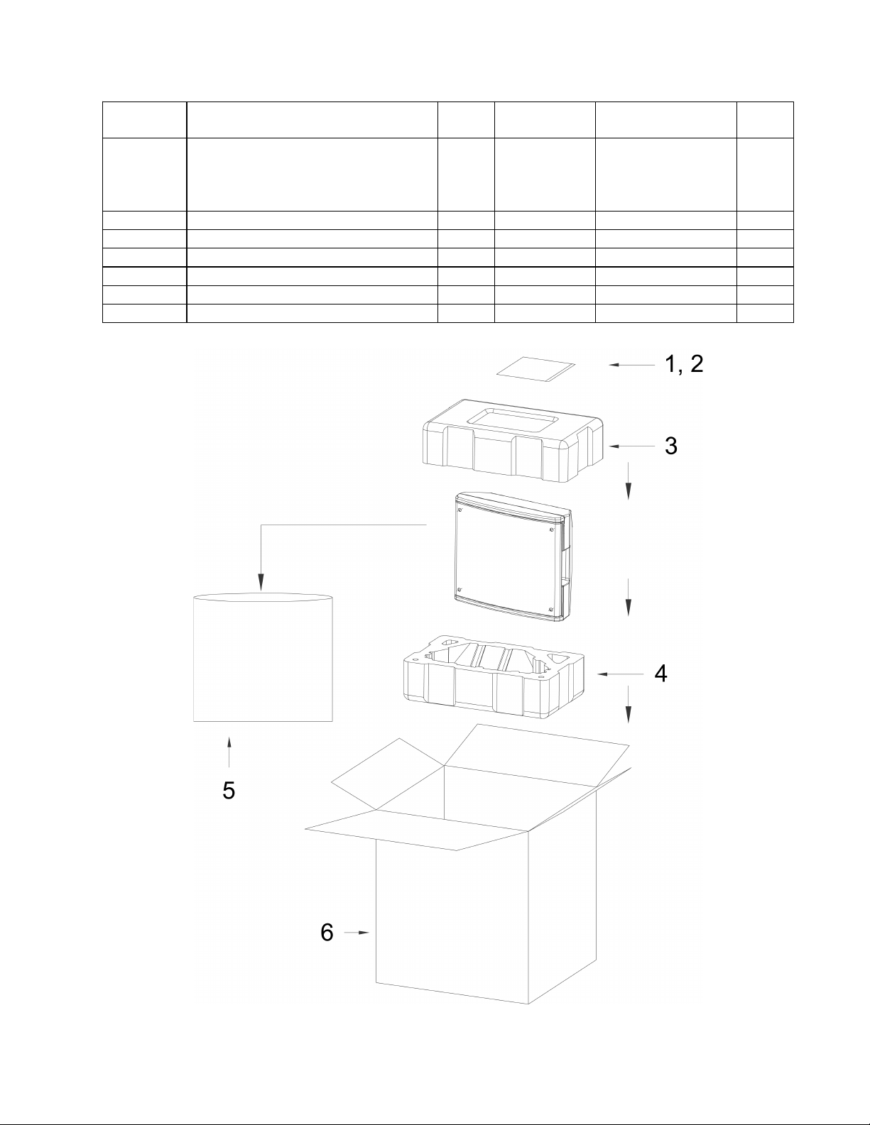
PACKAGING PART LIST
Panaray® Model 310M Loudspeaker
Item
Number
- KIT, CARTON (INCLUDES
FILLERS AND CARTON ONLY)
310M BLACK SPEAKER
310M WHITE SPEAKER
1 GUIDE, INSTALL 1 - 4301-7219+0 4
2 BAG, POLY (INSTALL GUIDE) 1 - 1497-4092-0 4
3 PACKING, FOAM, UPPER 1 - 1490-4561+0 4
4 PACKING, FOAM, LOWER 1 - 1490-4571+0 4
5 BAG, POLY 1 - 1497-7492+0 4
6 CARTON 1 - 1437-6901+0-2 4
Description Qty. Bose® Part
Number
1
295586-001
295586-002
Vendor Part
Number
-
-
Note
Figure 1. Panaray Model 310M Loudspeaker Packaging View
7
Page 8

PACKAGING PART LIST
Panaray® Model 620M Loudspeaker
Item
Number
- KIT, CARTON (INCLUDES
FILLERS AND CARTON ONLY)
620M BLACK SPEAKER
620M WHITE SPEAKER
1 GUIDE, INSTALL 1 - 4301-7219+0 4
2 BAG, POLY (INSTALL GUIDE) 1 - 1497-4092-0 4
3 PACKING, FOAM, UPPER 1 - 1490-4581+0 4
4 PACKING, FOAM, LOWER 1 - 1490-4591+0 4
5 BAG, POLY 1 - 1497-1072-4 4
6 CARTON 1 - 1437-7001+0-2 4
Description Qty. Bose® Part
Number
1
295585-001
295585-002
Vendor Part
Number
-
-
Note
Figure 2. Panaray Model 620M Loudspeaker Packaging View
8
Page 9

MAIN PART LIST
Panaray® Model 310M Loudspeaker (see Figure 3)
Item
Number
1 FASTENER, GRILLE, STEEL 4 - 4135-6181+0 4
2 GRILLE, BLACK
GRILLE, WHITE
3 PEF GASKET FOR GRILLE 2 - 4149-0881+0 4
4 SCREW, M4x10 (FOR INPUT
PANEL AND 5.25” DRIVER)
5 DRIVER, WOOFER, 5.25” 1 293304 WF-FM000C-EN
6 PEF GASKET FOR 5.25”
WOOFER
7 SCREW, M4x14 (FOR DRIVER
PANEL AND 2.25” DRIVERS)
8 EVA GASKET FOR 5.25”
WOOFER
9 DRIVER, 2.25” 3 293318 8900-3790+0
10 DRIVER PANEL (PC/ABS) 1 293322-001 4155-1741+0
11 PEF GASKET FOR DRIVER
PANEL
12 SCREW, M4x11 (FOR HANDLE) 4 - 2951-4011+5000 4
13 HANDLE, PC/ABS, BLACK
HANDLE, PC/ABS, WHITE
14 ENCLOSURE, BLACK
ENCLOSURE, WHITE
15 CROSSOVER ASSEMBLY 1 293324 -
16 3M TAPE, 9MMx5MIL - - 9500-9018+0 4
17 REAR BUMPER (SBR) BLACK
REAR BUMPER (SBR) WHITE
18 INPUT PANEL, BLACK
INPUT PANEL, WHITE
19
20 SCREW, M3x10, FOR NL4
CONNECTOR, NL4, NEUTRIK
CONNECTORS
Description Qty. Bose® Part
Number
1 293306-001
293306-002
8 - 2904-4010-3000 4
1 - 4153-3471-0 4
18 - 2954-4014-3000 4
1 - 4153-3591-0 4
1 - 4149-0701+0 4
2 293309-001
293309-003
1 293323-001
293323-002
1 293325-001
293325-003
1 293326-001
®
293326-002
2 - 2113-3140+0 4
4 - 2950-3010+3000 4
Vendor Part
Number
4135-6131+0
4135-6132+0
4155-1761+0
4155-1762+0
1467-5601+0
1467-5602+0
4157-1011+0
4157-1012+0
1405-8001+0
1405-8002+0
Note
4
9
Page 10

Figure 3. Panaray® Model 310M Exploded View
10
Page 11

MAIN PART LIST
Panaray® Model 620M Loudspeaker (see Figure 4)
Item
Number
1 GRILLE, BLACK
GRILLE, WHITE
2 WOOFER, 5.25” 2 293304 WF-FM000C-EN
3 HANDLE, BLACK
HANDLE, WHITE
4 DRIVER PANEL 1 293310-001 4155-1751+0
5 DRIVER, TWIDDLER, 2.25” 6 293311 WF-BS021C-EN
6 ENCLOSURE, BLACK
ENCLOSURE, WHITE
7 CROSSOVER ASSEMBLY 1 293313 -
8 REAR BUMPER, BLACK
REAR BUMPER, WHITE
9 INPUT PANEL, BLACK
INPUT PANEL, WHITE
10
11 SCREW (FOR GRILLE) 4 - 4135-6171+0 4
12 SCREW, M4, BLACK (FOR
13 SCREW, M4 (FOR HANDLE) 4 - 2954-4014+5000 4
14 SCREW, M4 (FOR 2.25” DRIVER
15 SCREW, M3 (FOR NL4
16 GASKET FOR GRILLE 2 - 4149-0881+0 4
17 GASKET FOR WOOFER, EVA 2 - 4153-3591-0 4
18 GASKET FOR WOOFER, PEF 2 - 4153-3471-0 4
19 GASKET FOR DRIVER PANEL 1 - 4149-0701+0 4
20 ADHESIVE, 3M - - 9500-9018+0 4
21 SCREW, INPUT PANEL, WHITE
CONNECTOR, NL4 NEUTRIK
WOOFER AND INPUT PANEL)
AND DRIVER PANEL)
NEUTRIK CONNECTORS)
(ALTERNATE FOR 12 ABOVE)
Description Qty. Bose® Part
Number
1 293305-001
293305-002
2 293309-001
293309-003
1 293312-001
293312-002
1 293314-001
293314-003
1 293316-001
®
12 - 2904-4010-3000 4
34 - 2954-4014-3000 4
293316-002
2 - 2113-3140+0 4
4 - 2950-3010+3000 4
4 - - 4
Vendor Part
Number
4135-6041+0
4135-6042+0
4155-1761+0
4155-1762+0
1467-5701+0
1467-5702+0
4157-1001+0
4157-1002+0
1405-8001+0
1405-8002+0
Note
4
11
Page 12

Figure 4. Panaray
®
Model 620M Exploded View
12
Page 13

DISASSEMBLY PROCEDURES
Panaray® Model 310M
Loudspeaker
Refer to the figure at right for
the following procedures.
1. Grille Removal
1.1 Remove the four screws
(1) using a Phillips-head
screwdriver.
1.2 Lift off the grille (2).
2. Handle Removal
2.1 Perform procedure 1.
2.2 Remove the two screws
(12). Lift off the handle (13).
3. Woofer Removal
3.1 Perform procedure 1.
3.2 Remove the four screws (4).
3.3 Lift out the woofer (5) and disconnect the
wires from the terminals.
Re-assembly Notes: Be sure to observe
polarity when connecting the new woofer to
the wiring harness.
4. Tweeter Driver Removal
4.1 Perform procedure 1.
4.2 Remove the four screws (7).
4.3 Lift out the driver (9) and disconnect the
wires from the terminals.
®
5. Neutrik
5.1 Remove the two screws (20) for the jack
you wish to remove.
5.2 Lift off the input jack (19). Cut the wires
as close to the jack as possible. Refer to the
wiring diagram in the back of this manual
when installing the new jack.
6. Crossover Assembly Removal
6.1 Perform procedure 3.
6.2 Disconnect the crossover harnesses
from the woofer, tweeters and input jacks.
6.3 Remove the four nuts that secure
the crossover assembly (15) to the input
panel (18). Lift out the crossover assembly.
Speakon® Jack Removal
Re-assembly Notes: Be sure to observe
polarity when connecting the new driver to
the wiring harness.
13
Page 14

DISASSEMBLY PROCEDURES
Panaray Model 620M
Loudspeaker
Refer to figure at right for the
following procedures.
1. Grille Removal
1.1 Remove the four screws (11)
using a Phillips-head screwdriver.
1.2 Lift off the grille (1).
2. Handle Removal
2.1 Perform procedure 1.
2.2 Remove the two screws (13).
Lift off the handle (3).
3. Woofer Removal
3.1 Perform procedure 1.
3.2 Remove the four screws (12).
3.3 Lift out the woofer (2) and
disconnect the wires from the
terminals.
Re-assembly Notes: Be sure to observe
polarity when connecting the new woofer to
the wiring harness.
4. Tweeter Driver Removal
4.1 Perform procedure 1.
4.2 Remove the four screws (14).
4.3 Lift out the driver (5) and disconnect the
wires from the terminals.
Re-assembly Notes: Be sure to observe
polarity when connecting the new driver to
the wiring harness.
5. Neutrik
5.1 Remove the two screws (15) for the jack
you wish to remove.
5.2 Lift off the input jack (10). Cut the wires
as close to the jack as possible. Refer to the
wiring diagram in the back of this manual
when installing the new jack.
6. Crossover Assembly Removal
6.1 Perform procedure 3.
6.2 Disconnect the crossover harnesses
from the woofer, tweeters and input jacks.
®
Speakon® Jack Removal
14
6.3 Remove the four nuts that secure
the crossover assembly (7) to the input
panel (9). Lift out the crossover assembly.
Page 15

TEST PROCEDURES
1. Phase Test
1.1 Observing polarity, momentarily apply a
12VDC level to pin 1+ and 1- of the Neutrik
NL4 connector.
1.2 While applying the DC voltage, observe
the drivers. They should all move outward
when the voltage is applied. Correct the
wiring on any drivers that move inward
instead of outward during this test.
2. Rub and Tick Test
2.1 Apply a 10Hz, 20Vrms signal directly to
the terminals of the driver under test. Refer
to the disassembly procedures in this
manual for the speaker under test to find out
how to remove the driver.
2.2 Listen for any extraneous noises such as
rubbing, scraping or ticking.
3. System Sweep Test
3.1 Apply a 10Hz, 20Vrms (310M speaker)
or 30Vrms (620M speaker) signal to pin 1+
and pin 1- of the Neutrik NL4 connector.
3.2 Sweep the audio signal generator from
10Hz up to 70Hz.
3.3 Verify that there are no extraneous
noises such as buzzes or rattles.
4. Air Leak Test
4.1 Apply a 70Hz, 20Vrms (310M speaker)
or 30Vrms (620M speaker) signal to pin 1+
and pin 1- of the Neutrik NL4 connector.
4.2 Listen for any air leaks around the rear
panel, input panel, woofer and handles.
Note: To distinguish between normal suspension noise and rubs or ticks, displace the
cone slightly with your fingers. If the noise
stays the same, it is normal suspension
noise and the driver is fine. Suspension
noise will not be heard with program material.
15
Page 16

Model 310M Crossover Board Layout Diagram
Item
Number
- - CROSSOVER PCB ASSY
1 C1 33UF +/-10%, 100V, DF
2 TML TERMINAL, OUTPUT - 4132-1551-0 2 4
3 LF #18AWG, TWIN, BL/BK,
4 HF #18AWG, TWIN, RED/BK,
5 TIE CABLE TIE, 150MM - 6360-1371+0 2 4
6 L1 3MH +/-2.5%, D 0.8MM - 1806-2689-0 1 4
7 C2 5UF +/-5%, 50V, DF MAX
8 L2 0.95MH +/-5%, AIR CORE - 1804-2200+0 1 4
9 R1 4 OHM, 20W, 5%, RWR,
10 PCB CROSSOVER PCB, BARE - 1725-404A+0000 1 4
Ref.
Des.
Description Bose® Part
CONSISTS OF:
<10%
250MM
400MM
3%
AL
Vendor Part
Number
293324 - 1
- 157H-3361+1-Y$ 1 4
- 7012-2440+0 1 4
- 7012-2450+0 1 4
- 157F-505J-5-YO 1 4
- 4741-4ROJ-1 2 4
Number
Qty. Note
16
Page 17

Model 620M Crossover Board Layout Diagram
Item
Number
- - CROSSOVER PCB ASSY
1 L2 0.45MH +/-5%, AIR CORE - 1804-2190+0 1 4
2 HF #18AWG, TWIN, BL/BK,
3 LF #18AWG, TWIN, RED/BK,
4 TML TERMINAL, OUTPUT - 4132-1551-0 2 4
5 L1 3MH +/-2.5%, D 0.8MM - 1806-2689-0 1 4
6 TIE CABLE TIE, 150MM - 6360-1371+0 2 4
7 R1 6 OHM, 5%, RWR, 20W,
8 C1 22UF +/-10%, 100V,
9 PCB CROSSOVER PCB, BARE - 1725-404A+0000 1 4
10 C2 20UF +/-10%, 50V,
Ref.
Des.
Description Bose® Part
CONSISTS OF:
500MM
400MM
AL
DF<10%
DF<10%
Vendor Part
Number
293313 - 1
- 7012-2450+0 1 4
- 7012-2440+0 1 4
- 4741-4ROJ-1 2 4
- 157H-3361+1-Y$ 1 4
- 157F-505J-5-YO 1 4
Number
Qty. Note
17
Page 18

Model 310M Crossover Board Wiring Diagram
Model 620M Crossover Board Wiring Diagram
18
Page 19

Service Manual Revision History
Date Revision
Level
1/06 00 Document released at revision 00. Service manual
Description of Change Change Driven
By
release
Pages
Affected
All
19
Page 20

Panaray® Model 310M and 620M
Loudspeakers
Model 310M Loudspeaker
Model 620M Loudspeaker
©2006 Bose Corporation
Service Manual
Reference Number 291484-SM Rev. 00
Electronic Copy Only
Page 21

SPECIFICATIONS AND FEATURES SUBJECT TO CHANGE WITHOUT NOTICE
Bose Corporation
The Mountain
Framingham Massachusetts USA 01701
P/N: 291484-SM Rev. 00 1/2006 (P)
http://serviceops.bose.com
 Loading...