

Page 1
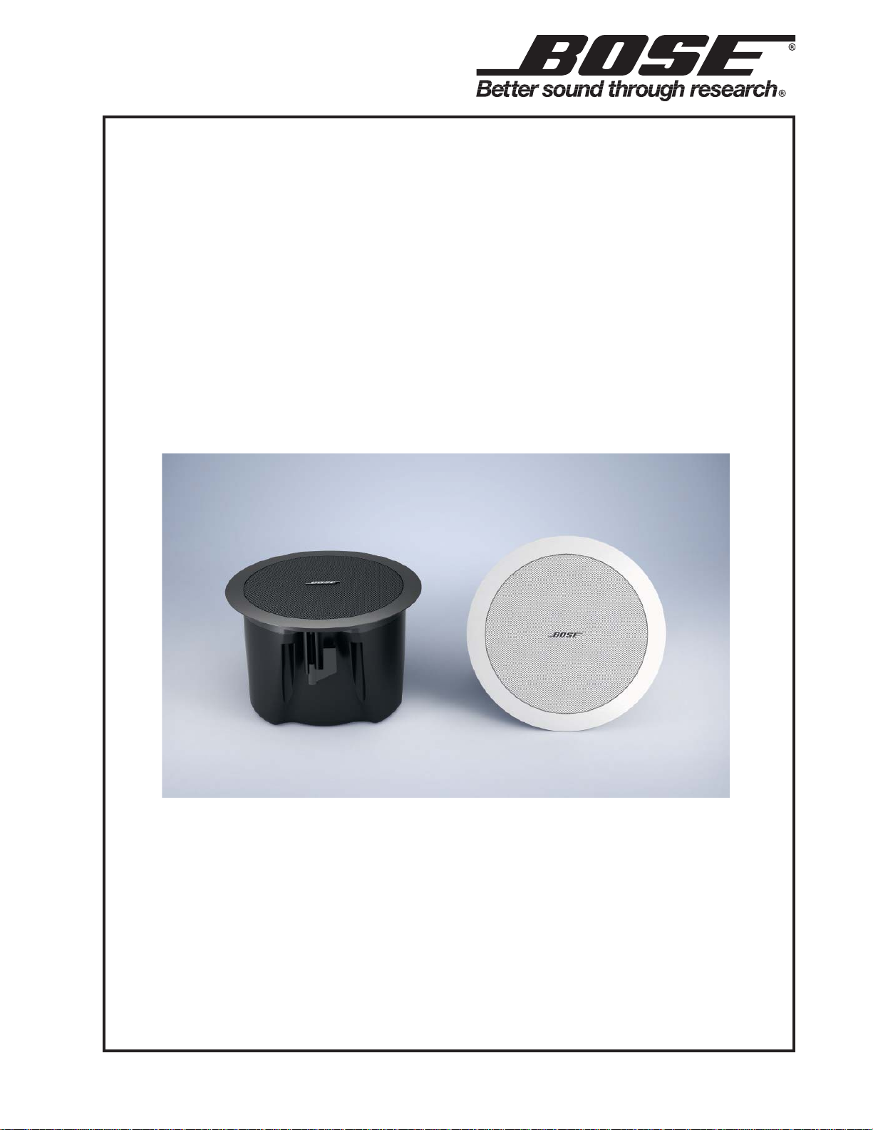
FreeSpace® DS 16F
Loudspeaker
©2009 Bose Corporation
Service Manual
Reference Number 303290-SM Rev . 00
Page 2
Contents
Description Product Code
Warranty .............................................................................................................................................2
Accessories .......................................................................................................................................2
Safety and Regulatory Compliance.................................................................................................3
Product Description .........................................................................................................................3
Specifications....................................................................................................................................4
Packaging Part List, FreeSpace® DS 16F Loudspeaker ............................................................... 5
Figure 1. FreeSp ace DS 16F Loudspeaker Packing V iew ..................................................................5
Main Part List, FreeSpace Model 16F ............................................................................................ 6
Figure 2. FreeSpace DS 16F Exploded V iew......................................................................................6
Disassembly Procedures .................................................................................................................7
Test Procedures ...............................................................................................................................8
DS 16F Test Setup Diagram.............................................................................................................8
CAUTION: The Bose® FreeSpace DS 16F loudspeaker contains
no user-serviceable parts. To prevent warranty infractions,
refer servicing to warranty service stations or factory service.
PROPRIET ARY INFORMATION
THIS DOCUMENT CONT AINS PROPRIET ARY INFORMA TION OF
BOSE CORPORA TION WHICH IS BEING FURNISHED ONLY FOR
THE PURPOSE OF SERVICING THE IDENTIFIED BOSE PRODUCT
BY AN AUTHORIZED BOSE SERVICE CENTER OR OWNER OF
THE BOSE PRODUCT, AND SHALL NOT BE REPRODUCED OR
USED FOR ANY OTHER PURPOSE.
W arranty
The Bose FreeSpace DS 16F loudspeaker is covered by a five year transferable limited warranty.
Accessories
Model 16 tile bridge (6 pack) 029830
Model 16 rough-in pan (6 pack) 029831
Model 16 retrofit kit (6 pack) 030096
PC-16 plenum cover (6 pack) 031144
Model 16 pendant mount kit, black 030094
Model 16 pendant mount kit, white 030095
2
Page 3

Safety and Regulatory Compliance
The FreeSpace® DS 16F loudspeaker has passed extensive testing and complies with the
following specifications and uses:
• Listed to ANSI/UL 1480-2005
• Fire Protective Signaling Use – UL CategoryUUMW , File Number S 3241. Control
Number42S9. Not for use with DC-supervised systems.
• General-Purpose Use – UL Category UEA Y, FileNumber S 5591 Control Number 3N89.
• Suitable for use indoors in damp locations.
• Suitable for installation using Class 1, Class 2 orClass 3 wiring methods in accordance with
NFP A70, National Electric Code, 2002, Article 640.
• Suitable for use with fire alarm circuit wiringmethods in accordance with NFPA 70,National
Electric Code, 2002, Article 760.
• Suitable for use in air handling plenum spaceswith a model PC-16 Plenum Cover installed.
• UL-2043, Fire Test and Visible Smoke Releasefor Discrete Products and their Accessories
Installed in Air Handling Sp aces.
• NFP A 70, National Electric Code, 2002, Article300-22 (c).
• NFP A 90-A, 2002, Inst allation of Air Conditioningand V entilation Systems, Paragraph
4.3.10.2.6.5.
• EMC Directive 89/336/EEC and Article 10 (1) of the directive, EN50081-1 and EN50082-1 as
signified by the CE mark.
The DS 16F also has been designed to therequirements defined in the following
Europeanregulatory specifications for combination systems:
• British Standard Code of Practice BS 5839, Part8 (with PC-16).
• T ested to IEC60268-5.
Product Description
The DS 16F loudspeaker is a 16-watt, ported loudspeaker system utilizing one 2.25" (57mm)
full-range driver. The loudspeaker is designed for installation in ceilings up to 20f t (6.1m) high. An
optional pendant-mount accessory allows the loudspeaker to be hung from open ceilings.
The loudspeaker has a nominal ratedimpedance of 8 ohms and is wired in parallel with a line
voltage matching (step-down) transformer with a selector switch appropriate for various output
taps. The loudspeaker input connections allow for direct connection to either 70V, 100V or lowimpedance amplifiers.
Exposed cosmetic surfaces of the loudspeaker are paintable, and the acoustically transparent
grille component is formed of powder-coated steel.
Each loudspeaker has a bandwidth of 90 Hz – 16 kHz and a maximum continuous acoustic
output of 96 dB-SPL, referenced to a full bandwidth pink noise input at 1 meter at the
loudspeaker’s rated power.
The input connection consists of a three-position barrier connector with a pre-wired ceramic
connector. The loudspeaker meets numerous standards for combination music and evacuation
systems around the world.
Power settings available are: 1W, 2W, 4W, 8W, 16W @ 70V; 2W, 4W, 8W, 16W @ 100V; and
16W @ 8½ (when referenced to IEC noisefor 100 hours). The nominal dispersion is 140°conical
coverage pattern at -6 dB (average 1 – 4 kHz).
3
Page 4

Specifications
Electrical
Power Handling: 16W
Nominal Impedance (transformer bypass): 8 Ohms
Sensitivity at 1W @ 1m 84dB SPL
Maximum SPL: 96 dB SPL
(pink noise at 1m at rated power) 102 dB SPL (peak)
Frequency Range ( -3dB): 90 Hz - 16 kHz
Beamwidth ( -6 dB point, average 1 -4 kHz): 140 degrees conical
Mechanical
Driver Complement: One 2.25” (57mm) full-range driver
Construction Features: Enclosure: PC/ABS rated at UL94 5V A
Grille: Power coated steel
Integral quick-install mounting features
Three mounting points at the rear of the housing
for pendant mounting
Dimensions: Outer flange diameter: 9.4” (239mm)
Ceiling hole diameter: 8” (203mm)
Height to top of housing: 6.2” (158mm)
Weight: Product: 4.4 lb (1.9kg)
Shipping: 6 lb (2.7kg)
Finish: Textured black or white finish with a contoured,
powder coated steel grille. Both the enclosure
and grille can be painted.
Connectors: Three-terminal barrier strip with a pre-wired
ceramic connector
Recommended Loudspeaker Equalization Curve
4
Page 5

Packaging Part List
Item
Description Bose® Part
Vendor Part
Note
FreeSp ace® DS 16F Loudspeaker
Number
Number
Number
1 SHIELD, PAINT - 1450-6700+0 4
2 OWNER’S MANUAL 299985 4301-7010+1
3 PE BAG - 1497-4732+0 4
4 PAPER STRIP - 1450-7900+0 4
5 PE BAG - 1497-4222+0 4
6 INNER CARD 1 324246-0010 1450-6340+0
7 INNER CARD 324243-0010 1450-6180+2
8 PE FORM 2 324241-0010 1493-0301+0
9 PE FORM 1 324242-0010 1493-0291+0
10 CARTON 313540 1436-0202+2-2
5
6
4
3
1
7
8
9
10
2
Figure 1. FreeSpace DS 16F Loudspeaker Packing View
5
Page 6

Item
Description
®®®®
Vendor Part
Qty.
Note
Main Part List
FreeSpace® Model 16F
Bose
Number
Part
Number
Number
1 WOOD SCREW, M4x12, 6.8 - 2910-4012+3000 16 4
2 SCREW, #8-32, WIRE CLAMP - 2AZZ-0007+ZZZZ 6 4
3 TERMINAL, 20x30x10, BS02XC 4135-6241+0 3
4 ANCHOR
BLACK
WHITE
303892
303893
4154-4982+1
4154-4981+1
4 WIRE, CON, #20, UL1015, L160 - 7012-6999 + 0 1
5 BAFFLE, WHITE - 4154-5064/5+6 1 4
6 SCREW, CLASS 1, PAN, M3.5x7 - 2A1 0-3575+3000 3 4
7 DRIVER, 2.25” (57MM) INDOOR 298081 8900-3840+0 1
8 KNOB 295898-003
2447-3602+1 1
10 EVA GASKET, 5x50 0 - 4153-3331 + 0 1.5 4
11 EVA GASKET, 3x51 5 - 4149-0311 + 0 1.5 4
12 SWITCH, ROTARY 5200-4933+1 1
13 CAP, ELECTROLYTIC, 200uF,
- 8910-0810+0 1
63V, 10%, NP, ALUM
14 WIRE ASSY, W110&SLEEVE - 7012-6369-+0 1
15 XFMR, AUDIO, 70/100V 296602 1806-3573+5 1
16 ENCLOSURE, DS16F - 4154-5051/2+2 1 4
17 TERMINAL, CERAMIC BLOCK - 2113-1956+0 1 3
18 THERMAL FUSE, RA TE D 100C - 8910-3595 + 1 1 3
19 UL 1007, WHITE - 1681-0090+C 0.1
20 SCREW, T4.0x20MM, TA PPING - 2910-4020+3000 2 4
21 JUNCTION BOX, BS02XC - 1404-6501+1 1
22 CLIP, RETAINING - 4135-2391+0 1
23 GRILLE, BLACK 296711 4135-2262+1 1
GRILLE, WHITE 296712 4135-2263+1
24 BOSE LOGO, BLACK 303977 4154-4992+0 1
BOSE LOGO, WHITE 303895 4154-4991+0
3
6
10
11
23
13
5
12
4
3
21
2
14
20
19
18
17
16
15
1
1
7
8
22
9
24
Figure 2. FreeSpace DS16F Exploded View
6
Page 7

Disassembly Procedures
Note: Refer to the figure below for the
following procedures.
1. Grille Removal
1.1 Carefully pull the grille (23) away from the
baffle (5). Take care to not mark the surface
of the grille or the baffle.
2. Driver Removal
2.1 Perform procedure 1.
2.2 Remove the four screws that secure the
driver (7) to the baffle (5).
2.3 Unplug the two faston connectors from
the wiring harness. Lift out the driver .
3. Rotary Switch Removal
3.1 Perform procedure 1.
3.2 Remove the TAP select knob (8).
3.3 Remove the six screws that secure the
baffle (5) to the enclosure (16).
3.4 Make a note of the wiring configuration
and unplug the three wires from the input
terminals.
3.5 Remove the nut that secures the rotary
switch (12) to the baffle. Lift out the rotary
switch.
Re-assembly Note: Be sure the rotary
switch is facing the correct direction and be
sure the lock washer is at "7" position when
you place the rotary switch onto the baffle.
4. Transformer Removal
4.1 Perform procedure 1.
4.2 Remove the six screws that secure the
baffle (5) to the enclosure (16).
4.3 Make a note of the wiring configuration
and unplug the three wires from the input
terminals.
4.4 Remove the nut that secures the rotary
switch (12) to the baffle.
4.5 Remove the screws that secure the
transformer (15) to the baffle. Lift out the
transformer.
Re-assembly Note: Be sure the rotary
switch is facing the correct direction and be
sure the lock washer is at "7" position when
you place the rotary switch onto the baffle.
6
10
11
13
5
12
4
3
2
1
16
17
18
19
1
21
20
15
14
7
8
22
9
23
24
7
Page 8

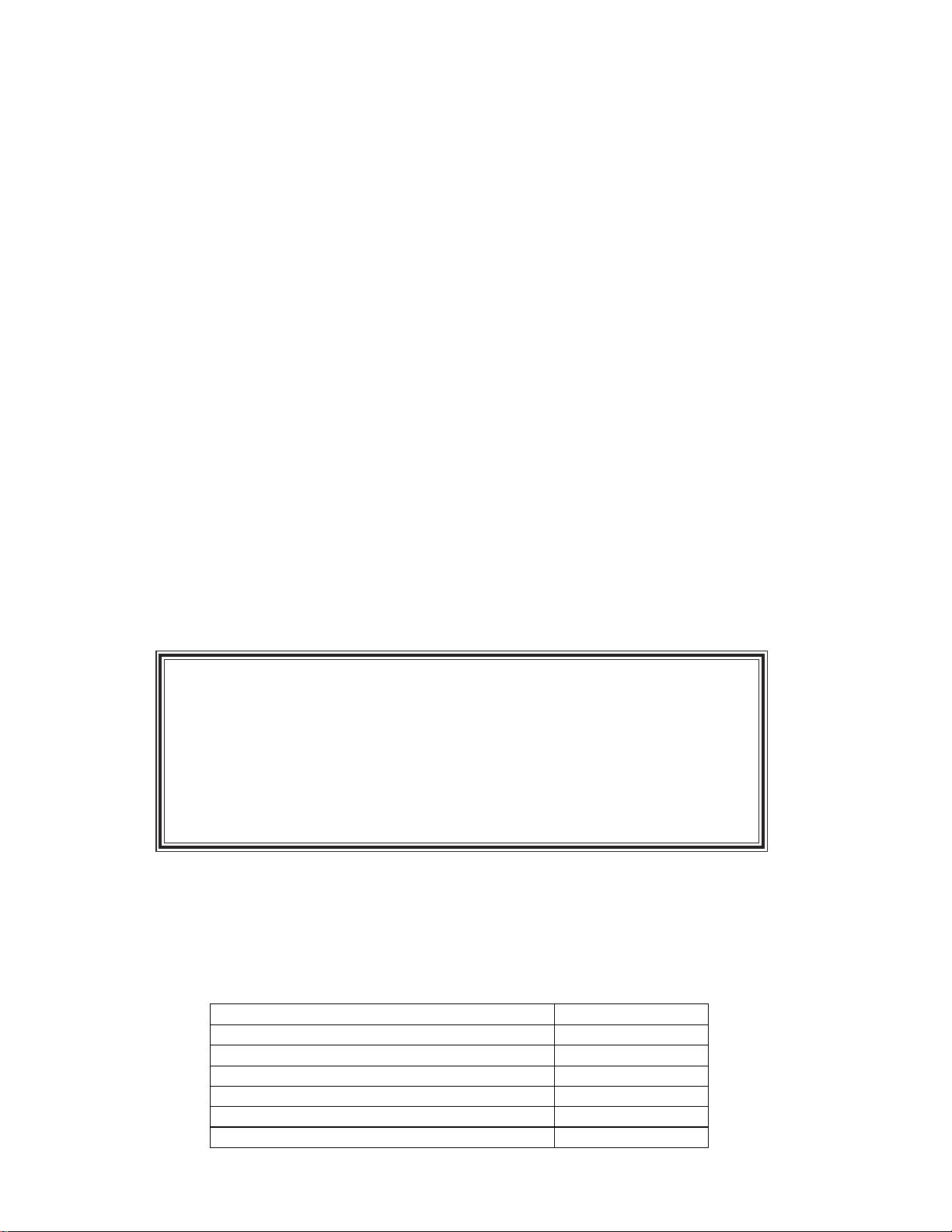
Test Procedures
Audio Signal
Generator
Power Amplifier
INPUT OUTPUT
FreeSpace DS 16F Test Setup Diagram
1. Phase Test
1.1 Turn the rotary switch to the 8 Ohm
position and apply a +6V DC level to the input
terminals with the positive lead connected to
the 8 Ohm terminal and the negative lead
connected to the COM terminal.
1.2 The driver should move outward when
the DC voltage level is applied.
2. Air Leak, Rub and Tick Test
2.1 Set up the system as shown in the figure
above.
Note: There is a normal suspension noise.
To distinguish between a rub or tick and
suspension noise, displace the cone slightly
with your finger. If the rubbing can be made
to go away, or gets worse, then it is a rub or
a tick. If the noise stays the same, it is
suspension noise.
3. System Sweep Test
3.1 Set the rotary switch to the 8 Ohm
position.
3.2 Apply a 6V rms, 80Hz signal to the input
terminals. Sweep the oscillator frequency
slowly from 80Hz to 16kHz. Listen carefully
for buzzes, rattles or other extraneous
noises from the driver or from the internal
parts. A whooshing noise from the port
around 80Hz is acceptable.
4. Transformer Tap Select Check
4.1 Apply a 70V rms, 100Hz signal to the input
of the loudspeaker under test. Slowly change
the tap selection on the unit from the high
position (16W) to the 1W position. A decrease in level should be heard for each
descending tap.
2.2 For the air leak, rub and tick, and power
sweep tests, all listening will be done at a
distance not to exceed 1 foot if the ambient
noise level is greater than 65dB. An air leak is
considered to exist when audible while facing
the baffle of the speaker assembly.
2.3 Apply a 6Vrms, 20Hz signal to the 8 Ohm
input terminals with the rotary switch at the 8
Ohm setting.
Reject any speaker with air leaks, except for
air leaks resulting from a defective driver or
gaskets. Replace any driver that has a
rubbing or ticking noise.
Small (quiet) ticks are acceptable if they
cannot be heard at a distance of 1 foot.
8
Page 9

SPECIFICATIONS AND FEATURES SUBJECT TO CHANGE WITHOUT NOTICE
Bose Corporation
The Mountain
Framingham Massachusetts USA 01701
P/N: 303290-SM Rev . 00 5/2009 (P) FOR TECHNICAL ASSIST ANCE OR P ART ORDERS, CALL 1-800-233-4408
http://serviceops.bose.com
 Loading...