

Page 1
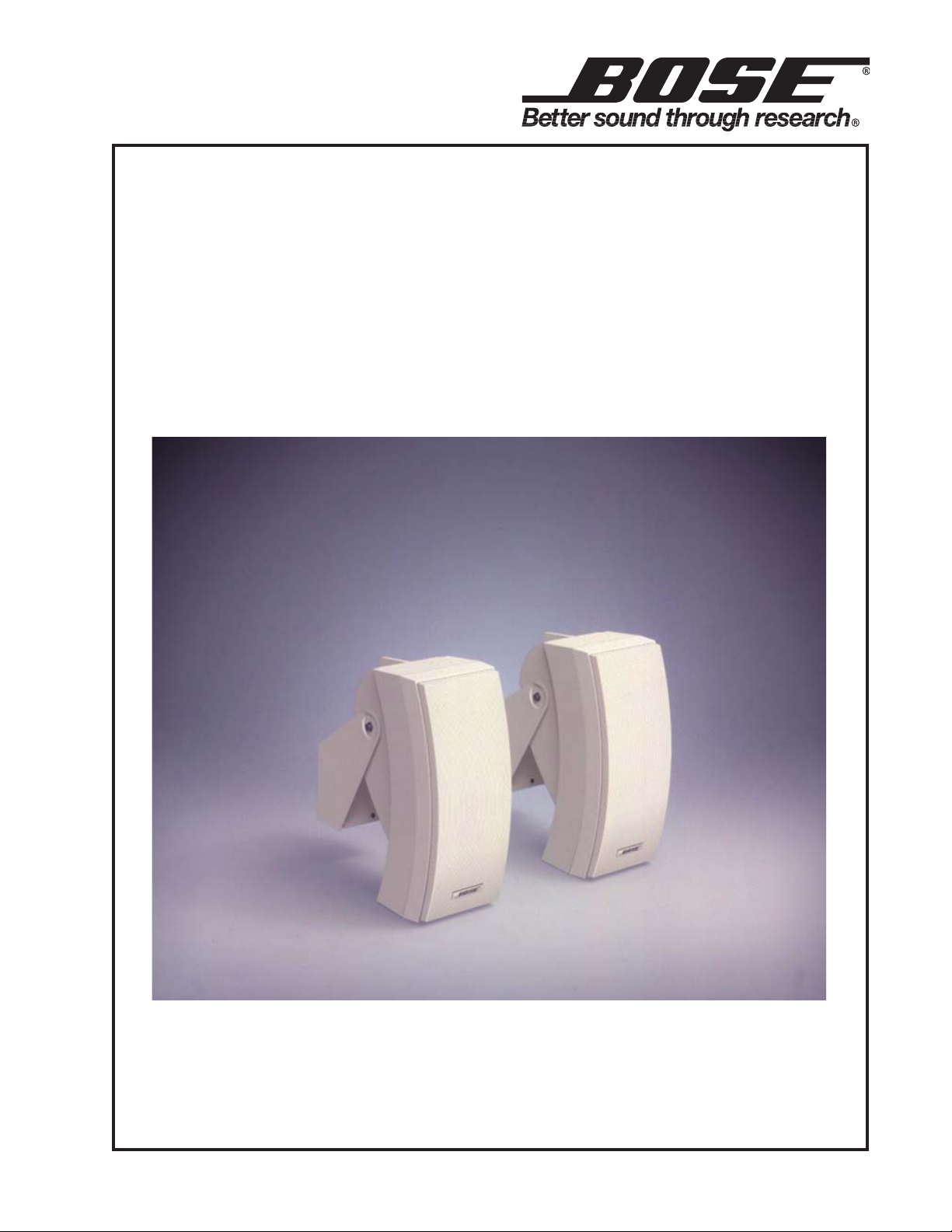
Bose® 302™A Loudspeaker
(Commercial Indoor/Outdoor
70V/100V Distributed Applications)
©2006 Bose Corporation
Service Manual
Part Number 257475 Rev. 02
Page 2

Contents
Product Description ......................................................................................................................... 2
Specifications ....................................................................................................................................3
Disassembly/Assembly Procedures ........................................................................................... 4-5
Transformer Wiring ........................................................................................................................... 5
Figure 2. Transformer Wiring ................................................................................................................ 5
Figure 1. Wiring Diagram ..................................................................................................................... 5
Test Procedures ................................................................................................................................6
Figure 3. Schematic Diagram ..............................................................................................................6
Part List .............................................................................................................................................. 7
Figure 4. Exploded View ...................................................................................................................... 7
Packaging Part List ........................................................................................................................... 8
Figure 5. Packaging View .................................................................................................................... 8
Table of contents ................................................................................................................................. 9
PRODUCT DESCRIPTION
The Bose® 302™ A loudspeaker is designed for surface-mount commercial 70V/100V distributed
indoor and outdoor applications. Designed to be mounted on a wall, ceiling or overhang, the 302A
loudspeaker is packaged with mounting brackets that contain a 70V or 100V multi-tap (12W, 25W,
50W and 100W) transformer. Each 302A loudspeaker contains one 5.25” environmentally resistant
woofer in a two-chamber configuration and two 2.5” environmentally resistant Twiddler™ drivers
vertically stacked and angled for maximum horizontal dispersion.
CAUTION: The Bose
serviceable parts. To prevent warranty infractions, refer
servicing to warranty service centers or factory service.
PROPRIETARY INFORMATION
THIS DOCUMENT CONTAINS PROPRIETARY INFORMATION
OF BOSE
ONLY FOR THE PURPOSE OF SERVICING THE IDENTIFIED
BOSE PRODUCT BY AN AUTHORIZED BOSE SERVICE CENTER OR OWNER OF THE BOSE PRODUCT, AND SHALL NOT
BE REPRODUCED OR USED FOR ANY OTHER PURPOSE.
The Bose 302A loudspeaker is covered by a five year transferable limited warranty.
CORPORATION WHICH IS BEING FURNISHED
302A loudspeaker contains no user
WARRANTY INFORMATION
2
Page 3

Transducers:
One 5.25" environmental woofer per enclosure
Maximum Acoustic Output:
SPECIFICATIONS
Two 2.5" environmental resistant TwiddlerTM drivers per enclosure
Crossover:
Low frequency cutoff:
Impedance:
Power Handling:
Transformer:
Frequency range:
Sensitivity:
Dispersion:
External Dimensions:
250Hz ±10% at 6dB/octave
-3dB at 75Hz ±5Hz
70V: 25 Ohms at 100W tap setting
100V: 50 Ohms at 100W tap setting
100W continuous per IEC 268-5
Multi-tap 70V/100V (12W, 25W, 50W,100W taps)
75Hz to 16 kHz
>82dB SPL at 1W, 1M (pink noise)
102dB SPL at 1M (pink noise)
102dB SPL at 1M (IEC noise)
(-6dB point, average, 1-4 kHz)
Horizontal 178
Vertical 93
o
o
Single speaker: 13.4"H x 5.7"W x 9.0"D (34 x 14.5 x 23) cm
Packed system: 16"H x 17"W x 14.75"D (40.6 x 43.2 37.47) cm
Weight:
Single speaker: 7.75 lb. (3.5 kg)
Packed system: 32.2 lb. (14.6 kg)
3
Page 4

DISASSEMBLY/ASSEMBLY PROCEDURES
(Refer to Figure 4)
1. Grille and Baffle Removal
1.1 Grasp the edge of the grill (10) and pull it
off.
1.2 Remove the six screws (17) that secure
the baffle to the cabinet and then pull off the
baffle.
2. Grille and Baffle Replacement
2.1 To prevent air leaks, apply a new woofer
mount gasket (13). To prevent wire buzzes,
insert the wires into the cabinet’s wire channel. Line up the baffle so that the baffle’s
woofer mount fits into the groove in the
cabinet. Replace the six screws (17) that
secure the baffle to the cabinet.
2.2 Align the grille (10) with the cabinet so
that the logo (14) is over the Twiddler
drivers (2). Press the grille into place.
TM
5.3 Remove the four screws (16) that secure
the woofer to the baffle. Lift out the woofer.
6. Woofer Replacement
6.1 To prevent air leaks, use a new woofer
gasket (15) and woofer mount gasket (13).
Line up the woofer (1) in the baffle so that the
wire terminal is facing toward the Twiddler
drivers (2). Replace the four screws (16) that
secure the woofer to the baffle.
6.2 Referring to the note taken in procedure
5.2, attach the wires to the woofer.
6.3 Place the foam tape woofer mount gasket
(13) around the edge of the woofer mount
where it contacts the cabinet.
7. RLC Circuit Component Removal
7.1 Perform procedure 1.
3. Twiddler Removal.
3.1 Perform procedure 1.1 and then remove
the four screws (16) that secure the Twiddler
driver (2) to the cabinet.
3.2 Lift out the Twiddler driver, make a note of
the wiring configuration and cut the wires as
close as possible to the wire terminal.
4. Twiddler Replacement
4.1 Referring to the note taken in 3.2, attach
the wires to the Twiddler driver (2).
4.2 Line up the Twiddler driver in the cabinet
and replace the four screws (16) that secure it
in place.
5. Woofer Removal
5.1 Perform procedure 1.
5.2 Make a note of the wiring configuration
and then cut the wires as close as possible to
the woofer’s (1) wire terminal.
7.2 Remove the capacitor (5), resistor (6) or
inductor (4) by cutting its leads. Remove the
screw (16) that secures the inductor to the
cabinet and cut the inductor’s leads.
8. RLC Circuit Component Replacement
8.1 Replace the capacitor (5), resistor (6) or
inductor (4) by soldering its leads to the lug
from which it was removed. Replace the
screw (16) that secures the inductor to the
cabinet. Refer to Figures 1 and 3.
9. Crossover Capacitor Removal
9.1 Perform procedure 1.
9.2 Remove the four screws (16) that secure
the Twiddler driver panel (11) to the baffle.
Pry off the panel.
9.3 Cut the wires as close as possible to the
terminals of the capacitor (3).
4
Page 5

DISASSEMBLY/ASSEMBLY PROCEDURES
(Refer to Figure 4)
10. Crossover Capacitor Replacement
10.1 Connect the leads of the capacitor (3) to
the wires and solder the connections. The
capacitor is wired in series with the woofer’s
(1) positive terminal and the Twiddler
TM
driver’s
(2) positive terminal. Refer to Figure 1 and 3.
10.2 To prevent air leaks, use a new Twiddler
driver panel (11) and gasket (12). Line up the
Twiddler panel with the cabinet and replace
the four screws (16) that secure it to the
baffle.
Boss 3
Boss 1
Red wire
(-) Woofer
(-) Terminal
Green wire
(-) Twid 2
Wiring Schematic
From To Wire
Twiddler
driver 1 (-)
Twiddler
driver 1 (+)
Capacitor
Twiddler
driver 2 (+)
Capacitor
(item number 3)
Woofer (+) Black
Yellow
(item number 3)
Twiddler
Lug at boss 3 Red
driver 2 (-)
Woofer (+) Terminal (+) Yellow
Woofer (-) Terminal (-) Green
Terminal (-) Lug at boss 1 Green
Gray
Figure 1. Wiring Diagram
TRANSFORMER WIRING
The transformer is set at the factory for 70V, 100W operation.
• To change from 70V to 100V operation, replace the orange wire with the yellow wire (orange wire
70V, yellow wire 100V).
• To change from 100W output, replace the red wire with:
• Green for 50W output
• Violet for 25W output
• Blue for 12.5W output
Caution: Do not remove or replace the black ground wire. To prevent wires from shorting, all
wires that are not connected must be covered with shrink tube or a wire nut.
OUTPUT
RED
BLK
INPUT
PARALLEL
INPUT
RED
BLK
100W
WHITE
ORANGE
JUMPER
WIRES
70V
YELLOW
GREEN
VIOLET
BLUE
100V
50W
25W
12.5W
Figure 2. Transformer Wiring
5
Page 6

TEST PROCEDURES
+
-
+
-
Gray
Twiddler driver 2
Twiddler driver 1
Red
15uF
1.5mH
11 Ohm
Woofer
GreenGreen
Yellow
YellowYellow
22uF
+
-
Test setup note: Disconnect the input of the
speaker from the transformer for procedures
1-5.
1. Woofer Rub and Tick Test
1.1 Apply a 1 Vrms, 10Hz signal to the
speaker input terminal. No extraneous noises
such as rubbing, scraping or ticking should be
heard.
Note: To distinguish between normal suspension noise and rubs or ticks, slightly displace
the cone of the woofer with your fingers. If the
noise can be made to go away or get worse, it
is a rub or tick and the woofer should be
replaced. If the noise stays the same, it is
normal suspension noise and the woofer is
okay. Suspension noise will not be heard with
program material.
2. Air Leak Test
4.4 Sweep the signal generator from 5 kHz to
15 kHz and then back to 5 kHz.
4.5 Listen for buzzes, rattles or other noises.
Redress any wire that buzzes; replace the
woofer or Twiddler driver if they are found to
be defective.
5. Woofer Phase Test
5.1 Observing polarity, momentarily apply 8
VDC to the speaker input terminal.
Note: To avoid damaging the speaker, only
momentarily apply the DC voltage.
5.2 The woofer should move outward with the
application of the DC voltage.
2.1 Apply an 8 Vrms, 65Hz signal to the
speaker input terminal.
2.2 Listen for air leaks around the cabinet
seams, the Twiddler™
woofer and Twiddler driver gaskets. Reposition or replace any gasket that is found to
leak. Repairs made to the cabinet seam
should not be visible from the exterior of the
speaker.
Note: A whooshing noise from the ports at
approximately 65Hz and 185Hz is acceptable
(port tuned frequencies).
3. Twiddler Driver Phase Test
3.1 Check the wiring of the Twiddler driver
against Figures 1 and 3.
4. Sweep Test
4.1 Apply an 8 Vrms, 10Hz signal to the
speaker input terminal.
4.2 Sweep the signal generator from 10Hz to
5 kHz and then back to 10Hz.
4.3 Apply a 3 Vrms, 5 kHz signal to the
speaker input terminal.
driver panel, and the
Figure 3. Schematic Diagram
6. Transformer Test
6.1 Connect the output of the transformer to
the speaker input terminal.
6.2 Apply a 35 Vrms, 50Hz signal to the input
of the transformer.
6.3 Sweep the signal generator from 50Hz to
5 KHz. Listen for clean undistorted audio
output.
6
Page 7

MAIN PART LIST
Item
Description Part Number Qty Note
Number
1 WOOFER, 5.25", ENVIRONMENTAL 289780-001 1
2 TWIDDLERTM DRIVER, ENVIROMENTAL 289783-001 2
3 CROSSOVER ASSY, 22UF 291731-002 1
4 INDUCTOR, 1.5mH, 0.8 OHM, FERRITE 147196 1
5 CAPACITOR, BIPOLAR, 15uF 291087-001 1
6 RESISTOR, WW, 5W, 10%, 11.1 OHM 125605-110 1
7 NUT, INSERT 250818 2
8 CONNECTOR, ENVIRONMENTAL, BLACK 250815-01 1
9 CONNECTOR, ENVIRONMENTAL, RED 250815-02 1
10 GRILLE, ALUMINUM, BLACK
GRILLE, ALUMINUM, WHITE
250804-11
250804-12
1
11 PANEL, SEALING, TWIDDLER DRIVER 250820 1
12 FOAM TAPE GASKET 250807 1
13 FOAM TAPE GASKET, WOOFER MOUNT 250808 1
14 LOGO, BLACK CABINET
LOGO, WHITE CABINET
250806-03
250806-04
1
15 GASKET, 134mm, RD, ADH BACKE D 290315-001 1
16 SCREW, TAPP, 8-11X.5, PAN, ASY, SQ 290306-08 17
17 SCREW, TAPP, 8-11X1.0, PAN, ASY, SQ 290306-16 7
18 GASKET .725" ROUND 293356-001 2
19 SCREW, TAPP, 8x3/8, HEX W, SLOT 290304-06 2
20 CONN, TERM, WIRE WRAP, 1 POS, FEM 118008 2
21 TAPE, FOIL 255912 2
22 TAPE, FOAM 255911 1
23 TAPE, FOAM 118223 2
24 TAPE, FILTER FOAM 255910 1
25 SCREW 290305-16 1
Red wire
(-) Woofer
(-) Terminal
25
4
5
6
21
Green wire
23
(-) Twid 2
Figure 4. Exploded View
7
Page 8

3
7
6
4
5
1
8
9
10
2
PACKAGING PART LIST
Item
Description Part Number Qty Note
Number
1 BRACKET/TRANSFORMER, 70V/100V BLACK
BRACKET/T RANSFORMER, 70V/100V WHITE
255901-01
255901-02
1
pkg of 2
2 70V/100V TRANSFORMER ONLY 254426 2
3 HARDWARE KIT, ENV, 4-PACK, BLACK
HARDWARE KIT, ENV, 4-PAC K, WHIT E
290307-003
290307-004
1
4 BAG, POLY, HDPE, 18X26, 1 MIL 255354-001 1 4
5 PACKING , END CAP, TOP 250809 1
6 PACKING, END CAP, BOTTOM 250810 1
7 CARTON, RSC 255902-001 1
8 PACKAGING, CREASE SHEET 255903 1
9 INSTALLER GUIDE 255917 1
10 COMMITMENT LETTER 251001 1
Figure 5. Packaging View
8
Page 9

Date Revision
Description of Change Change
Pages
SERVICE MANUAL REVISION HISTORY
Level
8/02 00 Document release revision 00
Unknown 00 to 01 ECN 33972 and 33783 6,7
02/06 01 to 02 Added RoHS part numbers This product is
1
Driven By
Service
manual
release
now built with
RoHS
compliant
parts.
Affected
All
6,7
9
Page 10

Specifications and Features Subject to Change Without Notice
Bose Corporation
The Mountain
Framingham Massachusetts USA 01701
P/N 257475 REV. 02 2/2006 For Technical Assistance or Part Orders, Call 1-800-233-4408
 Loading...