

Page 1

Contents
Warranty.............................................................................................................................................1
Specifications ....................................................................................................................................2
Technical Description .......................................................................................................................2
Disassembly/Assembly Procedures ........................................................................................... 3-4
Figure 1. Woofer Wiring Configuration ............................................................................................... 3
Figure 2. Test Equipment Set Up .......................................................................................................4
Test Procedures ................................................................................................................................ 5
Main Part List.....................................................................................................................................6
Figure 3. Exploded View ................................................................................................................... 6
Crossover Part list ............................................................................................................................ 7
Figure 4. Crossover Diagram............................................................................................................7
Packaging Part List ........................................................................................................................... 8
Figure 5. Packaging Exploded View..................................................................................................8
®
CAUTION: The Bose
no user-serviceable parts. To prevent warranty infractions,
refer servicing to warranty service stations or factory service.
Model 301
®
Series V loudspeaker contains
WARRANTY
The Bose Model 301 Series V loudspeaker is covered by a five-year limited warranty.
PROPRIETARY INFORMATION
THIS DOCUMENT CONTAINS PROPRIETARY INFORMATION OF
BOSE CORPORATION WHICH IS BEING FURNISHED ONLY FOR
THE PURPOSE OF SERVICING THE IDENTIFIED BOSE PRODUCT
BY AN AUTHORIZED BOSE SERVICE CENTER OR OWNER OF THE
BOSE PRODUCT, AND SHALL NOT BE REPRODUCED OR USED
FOR ANY OTHER PURPOSE.
1
Page 2

SPECIFICATIONS
Dimensions: Single Speaker: 9.375" H x 14.625" W x 9.375" D
(25 x 36 x 25 cm)
Weight: Packed pair: 28.7 lb (16.5 kg)
Single speaker: 12.5 lb (5.7 kg)
Transducer
complement: One 8" woofer
Two 2" tweeters
Internal cabinet
volume: 961 cu in (15.8 liters)
Port: Description: Dual flared ports molded as part of the rear panel
ports tuned to 48 Hz
Low frequency cutoff: -3 dB at 55 Hz or lower
Impedance: 6 Ohms 4.8 Ohms minimum, 50 Hz to 15 kHz
per IEC-268-5
Power handling: 75 W (21.2 Vrms) continuous per IEC 268-5 for a
duration of 100 hours. Recommended amp/receiver
power 10 to 150 Watts per channel
Sensitivity: 1Vrms, 1 meter: = 79 dB SPL, 400 Hz octave
PRODUCT DESCRIPTION
®
The Bose
two-piece (mirror imaged stereo pair) home loudspeaker in a bookshelf configuration.
The 301 Series V is designed for use with standard amplifiers, receivers, and other related
home audio components.
The 301 Series V utilizes separate inward and outward firing tweeters to achieve consistent
stereo imaging over a broad listening area (Stereo Everywhere® performance) while maintaining a spacious sound stage.
Aesthetically, the 301 Series V echoes styling cues successfully used in the 601® Series IV
and the 701
features a molded plastic front panel, integrated with a vinyl-covered particle board enclosure.
®
301
Series V is a replacement for the 301 Series IV speaker, and is a passive,
®
Series II, and has a family resemblance to the 201® Series V. The 301 Series V
Additionally, the system incorporates slot-port technology which reduces port noise and produces cleaner, more natural bass. The sum of all these unique features makes the 301 Series
V speaker capable of reproducing the wide dynamic range demanded by today's advanced
recordings without strain or loss of clarity.
2
Page 3
DISASSEMBLY/ASSEMBLY PROCEDURES
Note: Refer to figure 3 for the following
procedures.
1. Grille Removal
1.1 Grasp the top and bottom edges of the
grille (12) and pull off the grille.
2. Grille Replacement
2.1 Align the grille (12) so that the Bose
logo (11) is right side up on the tweeter
side of the cabinet and push it into place.
3. Woofer Removal
3.1 Perform procedure 1.
3.2 Remove the four screws (13) that
secure the woofer (14) to the cabinet.
3.3 Lift the woofer out and cut the wires as
close to the terminals as possible.
4. Woofer Replacement
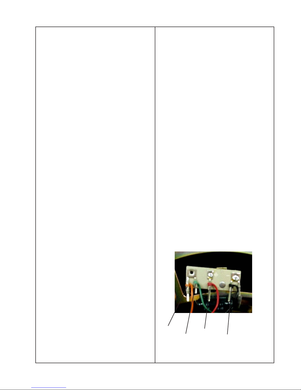
4.1 Strip the wires and connect the wires as
shown in figure 1. The red wire to the single
center terminal. The black wire to the right
side double terminal (looking at the woofer
magnet side down). The orange and green
wires to the left double terminal. The
capacitor is connected to the far left and
right terminals.
5.3 Lift the tweeter out of the cabinet and
cut the wires as close to the terminals as
possible.
6. Front Tweeter Replacement
6.1 Strip the wires and connect the red
wire to the positive (+) terminal and the
black wire to the negative (-) terminal.
Dress or twist the wires to prevent buzzes.
®
6.2 Place the tweeter (8) into the cabinet
and secure it using the tweeter bracket (7)
and screw (6).
6.3 Perform procedures 4.2 and 2.
7. Rear Tweeter Removal
7.1 Perform procedures 1, 3.2 and lift the
woofer out of the cabinet, but do not cut the
wires.
7.2 Using a 1/4 inch wrench, remove the
screw (1) and bracket (2) that secures the
tweeter (3) to the cabinet.
7.3 Lift the tweeter out of the cabinet and
cut the wires as close to the terminals as
possible.
4.2 Secure the woofer (14) to the cabinet
using four screws (13).
4.3 Perform procedure 2.
5. Front Tweeter Removal
5.1 Perform procedures 1, 3.2 and lift the
wooter out of the cabinet, but do not cut the
wires.
5.2 Using a 1/4 inch socket, remove the
screw (6) and bracket (7) that secures the
tweeter (8) to the cabinet.
orange
green
red
black
Figure 1. Woofer Wiring Configuration
3
Page 4

DISASSEMBLY/ASSEMBLY PROCEDURES
8. Rear Tweeter Replacement
8.1 Strip the wires and connect the red wire
to the positive (+) terminal and the black
wire to the negative (-) terminal. Dress or
twist the wires to prevent buzzes.
8.2 Place the tweeter (3) into the cabinet
and secure it using the tweeter bracket (2)
and screw (1).
8.3 Perform procedures 4.2 and 2.
9. Terminal Block Connector Removal
9.1 Perform procedures 1, 3.2 and lift the
woofer out of the cabinet, but do not cut the
wires.
9.2 Unclip the terminal block connector
(4) from the inside of the cabinet and push
it out through the rear panel. Cut the wires
as close to the terminals as possible.
10.1 Terminal Block Connector
Replacement
10.1 Strip the wires and connect the red
wire to the positive (+) terminal and the
black wire to the negative (-) terminal.
Dress or twist the wires to prevent buzzes.
10.2 Secure the terminal block connector
(4) to the cabinet.
10.3 Perform procedure 4.2 and 2.
Audio Signal
Generator
_
Power Amplifier
Input Output
+
+
_
Speaker
+
_
+
_
Figure 2. Test Equipment Set Up
4
Page 5

TEST PROCEDURES
Note: Remove the grille for the following
tests.
General Test Set Up
Connect the output of a signal generator to
the input of a power amplifier. Connect the
output of the power amplifier to the input
terminals of the speaker under test. Refer
to figure 2, (on page 4) test equipment set
up.
1. Woofer Rub and Tick Test
1.1 Apply a 7 Vrms, 10 Hz signal to the
input terminals of the speaker under test.
No extraneous noises such as rubbing,
scraping or ticking should be heard.
Note: To distinguish between normal suspension noise and rubs or ticks, displace
the cone on the woofer slightly with your
fingers. If the noise can be made to go
away or get worse, it is a rub or a tick and
the woofer should be replaced. If the noise
stays the same, it is a normal suspension
noise and the woofer is fine. Suspension
noises will not be heard with program
material.
3.2 Sweep the input generator from 10 Hz
to 5 kHz. There should be no extraneous
sounds.
3.3 Reduce the input voltage to 3 Vrms, and
continue sweeping from 5 kHz to 15 kHz.
3.4 Redress any wires or components that
buzz or rattle. Replace any woofer or
tweeter that is found to be defective.
4. Phase Test
Note: The supply voltage should only be
momentarily applied to the speaker input
terminals to avoid possible damage to the
speaker.
4.1 Set a DC power supply to 9 volts.
Connect the positive wire from the power
supply to the positive (+) connector of the
input terminal and the negative wire to the
negative (-) connector of the input terminal.
The woofer should move outward with the
application of the supply voltage.
2. Air Leak Test
2.1 Apply a 7 Vrms, 35 Hz signal to the
input terminals of the speaker under test.
2.2 Listen for air leaks around the woofer,
tweeters and cabinet seams. Any air leaks
will be heard as a sputtering or hissing
sound.
2.3 Replace or reposition any gasket where
an air leak can be heard.
3. Sweep Test
3.1 Apply a 7 Vrms, 10 Hz signal to the
input terminals of the speaker under test.
5
Page 6

MAIN PART LIST
Item
Number
1 SCREW, MACH, SEMS, 8-32, HEX 256070-08 1
2 CLIP, TWTR RETAIN, REAR 264973-03 1
3 TWEETER, 2", REAR
TWEETER, 2", REAR, SHLD
4 CONN, BARRIER GLTN, 2 POS 181865 1
5 BATTING, POLYESTER 116082 or 260336 1
6 SCREW, MACH, SEMS, 8-32, HEX 256070-08 1
7 CLIP, TWTR RETAIN, FRONT 264973-01 1
8
9 GASKET, WOOFER, 8" 266118 1
10 GROMMET, GRILLE SOCKET 176068 4
11 NAMEPLATE, LOGO 266108 1
12 GRILLE ASSY, BLACK 266105-01 1
13 SCREW, TAPP, 8-11 x .75, PAN, XRC/SQ 172672-12 4
14 WOOFER ASSY, 8", (WITH TRIM RING) 289908-001 1
Note 4: When replacing the tweeters, replace with like tweeter.
If the front tweeter has a silver trim use 290845-01 for the rear and 290847-01 for the front
If the front tweeter has a black trim, use 290836-01 for the rear and 290813-01 for the front
TWEETER, 2", FRONT, (WITH SLIVER TRIM SKIRT)
TWEETER, 2", FRONT, (WITH BLACK TRIM SKIRT)
Description Part
Number
290845-01
290836-01
290847-01
290813-01
Qty. Note
1
1
Figure 3. Exploded View
6
Page 7

CROSSOVER PART LIST
Note
Reference Designator Description Part Number
C1
C2
RT1 LAMP, MINI, 1.5A, 36VDC 141989
4.0uF, EL, BP, 85°C, 50V, 10%
15uF, EL, BP, 85°C, 50V, 10% (ON
WOOFER)
116542
126798
Figure 4. Crossover Diagram
7
Page 8

PACKAGING PART LIST
Number
Note
Item
1 MANUAL, OWNER'S 264981 1
2 INFO CARD, WARRANTY, MULTI LANG 181460 1
3 CARD, REGISTRATION AND WARRANTY 262933 1
4 BUMPER, FOOT, ADH BACKED, 8-CT 173012-08 1
5 ADDRESS PAGE 259434 1
6 SHEET SLIP ALL PRODUCTS 255808 1
7 COMMITMENT LETTER 251001 1
8 BAG, POLY, 14.38" x 9.87" x 2 mil 103351 1
9 BAG, POLY, HDPE 13.5" x 35" x 9.5" x 1MIL 114522 1
10 PACKING, EPS 266123 4
11 CARTON, RSC 266122-01 1
Description Part
Number
Qty.
Figure 5. Packaging Exploded View
8
Page 9

Bose® Model 301
Loudspeaker
®
Series V
©
2002 Bose Corporation
Service Manual
Part Number 267215 Rev. 00
Page 10

SPECIFICATIONS AND FEATURES SUBJECT TO CHANGE WITHOUT NOTICE
Bose Corporation
The Mountain
Framingham Massachusetts USA 01701
P/N: 267215 Rev. 00 10/2002 (H) FOR TECHNICAL ASSISTANCE OR PART ORDERS, CALL 1-800-223-4408
http://serviceops.bose.com
 Loading...