

Page 1

301 ® SERIES III DIRECT/REFLECTING® SPEAKER SYSTEM
SPECIFICATIONS
Transducers: Cabinet:
1-8"(20 cm) woofer Black, white, or walnut-grained finish
2-3"(7.6 cm) tweeters
Nominal Impedance: Speaker Dimensions:
8 Ohms 10.5"H x 17"W x 9.5" D
(27 H x 43 W x 24 D cm)
IEC Power Rating: Shipping Weight
Min: 10 Watts Per Channel 34 lbs. (15.5 kg) Per Pair
Max: 75 Watts Per Channel
Service Manual
Page 2

BOSE ® 301 ™ SERIES III TECHNICAL DESCRIPTION
The BOSE 301 Series III System is an economical way to enjoy the legendary spatial
®
realism of a Direct/Reflecting
system. This system creates a natural balance of reflected
and direct sound that conventional speaker designs can’t match. The result is lifelike
spaciousness that approaches the realism of a live performance. Even sound distribution
also enables the listener to sit or stand anywhere and still hear the same volume and blend
of musical instruments.
This achievement is also aided by three high performance drivers in each cabinet: one 8"
woofer and two 3” tweeters. The tweeters are arranged in a three-dimensional Free Space
Array which is mounted slightly away from the cabinet face. One tweeter is aimed inward
toward the center of the listening area. The second tweeter is aimed outward so that its
output is reflected off the side wall. This arrangement provides the excellent spatial
characteristics of a Direct/Reflecting
®
system.
The 301 system employs the BOSE Dual Frequency ™ crossover network. The crossover
provides a smooth transition from low to high frequencies by sending sound to all the
drivers over nearly a full octave. The result is a clear definition of each instrument and
voice.
®
Additionally, the system incorporates slot-port technology which reduces port noise and
produces cleaner, more natural bass. The sum of all these unique features makes the 301
Series III speaker capable of reproducing the wide dynamic range demanded by today’s
advanced recordings without strain or loss of clarity.
TEST PROCEDURES
NOTE: Before performing any tests,remove the grille assembly. Refer to the Grille
Assembly Removal procedure.
1. Woofer Rub and Tick Test
A. Connect a sine wave oscillator to a power amplifier. Adjust the frequency of the oscillator
to 10 Hz and the amplifier output to 8 Vrms. Connect the amplifier output to the input
terminals of the 301-III speaker (see Figure 1). No extraneous noises such as rubbing,
scraping or ticking should be heard.
1
Page 3
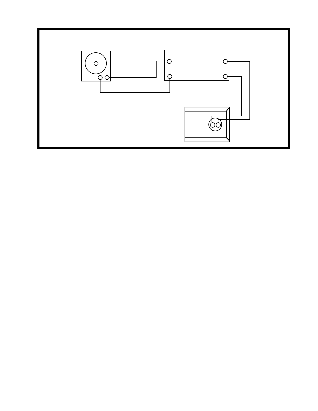
Audio Signal
Generator
Test Connections 301 III Speaker
Power Amplifier
Input Output
--
+
-
++
Speaker
-
+
FIGURE 1
NOTE: To distinguish between normal suspension noise and rubs or ticks, displace the
cone on the woofer slightly with your fingers. If the noise can be made to go away or get
worse, it is a rub or a tick and the woofer should be replaced. If the noise stays the same, it
is normal suspension noise and the woofer is fine. Suspension noises will not be heard with
program material.
2. Woofer Sweep Test
A. Sweep the oscillator from 10 Hz to 3 kHz using the 8 Vrms signal. There should not be
any loud extraneous sounds. If there are any loud buzzes or distortion, replace the woofer.
NOTE: There should not be any buzzes or rattles from within the speaker cabinet. Redress
any wire or component that buzzes.
3. Tweeter Sweep Test
A. Reduce the amplifier output to 4.0 Vrms and continue sweeping from 3 kHz to 15 kHz.
If one of the tweeters is buzzing or distorting, replace it.
4. Air Leak Test
A. Using the 8 Vrms signal, set the oscillator frequency to 45 Hz. For at least 5 seconds,
listen for air leaks around the woofer,terminal cup and tweeter mounting brackets. If there is
a "whooshing" noise around the woofer, re-position the woofer gasket behind the woofer to
make an airtight seal. If there are any similar noises around either of the tweeter mounting
brackets or the terminal cup, make sure that these items are securely fastened to the
speaker assembly.
2
Page 4
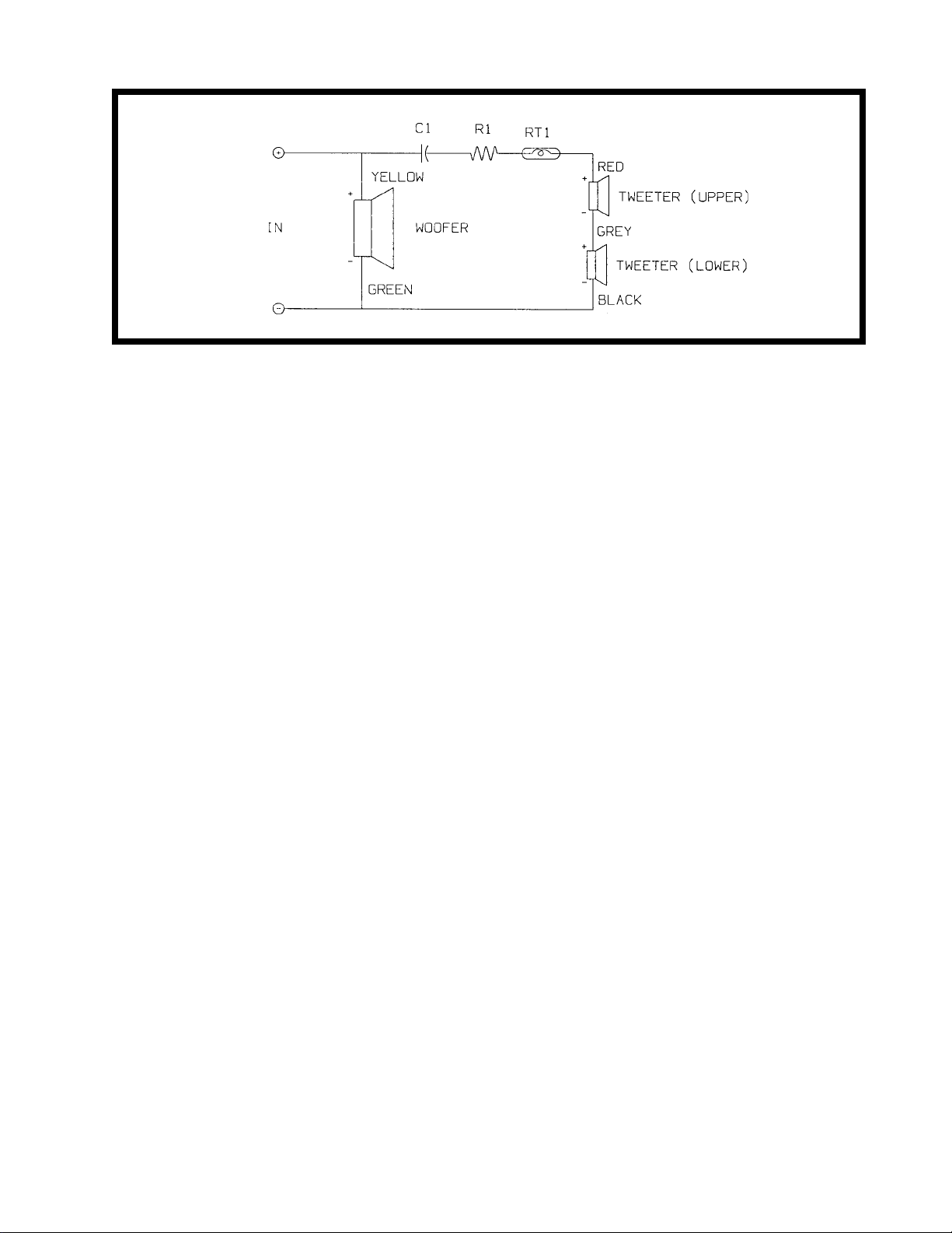
Schematic Diagram
FIGURE 2
5. Woofer Phase Test
NOTE: Supply voltage should only be momentarily applied to the speaker input terminals to
avoid possible damage to the speaker.
A. Set a DC power supply to 8 volts. To ensure that the woofer is connected in phase,
connect the positive lead of the supply to the positive (+) speaker input terminal and the
negative lead to the negative (-) input terminal. The woofer should move outwards with the
application of the supply voltage.This ensures that the woofer and speaker input terminals
are wired in phase. See Schematic Diagram, Figure 2.
6. Tweeter Phase Test
A. Remove 4 screws and lift the woofer carefully away from the speaker cabinet in order to
access the terminal cup. Check the wiring on the terminal cup and on both sets of tweeter
terminals against the schematic in Figure 2. This ensures that both tweeters are wired in
phase.
REMOVING THE GRILLE ASSEMBLY
A. The grille assembly is held in place by 6 grille fasteners. To remove, CAREFULLY pull
the assembly away from the speaker (it should lift away easily).
REPAIR PROCEDURES
1. Replacing the Woofer
A. Remove the 4 screws holding the woofer in place. (Refer to Figure 3 for an exploded
view of the speaker assembly). Lift the woofer out and cut the wires connected to the
woofer terminals as close to the terminals as possible. Strip the wires and connect to the
replacement woofer. Make sure that the yellow wire is connected to the positive (+) terminal
and the green wire is connected to the negative (-) terminal of the woofer. Remount the
woofer to the cabinet using the 4 screws. Repeat the woofer test procedure.
3
Page 5

2. Replacing the Tweeters
NOTE: The positive terminal of each tweeter is marked with a red dot.
A. The upper and lower tweeters are mounted on brackets. Refer to Figure 3. Remove one
(1) screw which secures either tweeter to its bracket. Lift the tweeter away from the bracket
and cut the wires connected to the tweeter as close to the tweeter terminals as possible.
Strip the wires and connect to the replacement tweeter. The tweeters should be wired as
follows:
(1). Upper Tweeter-Make sure that the red wire is connected to the positive (+) terminal
and the grey wire is connected to the negative (-) terminal.
(2). Lower Tweeter-Make sure that the grey wire is connected to the positive (+) terminal
and the black wire is connected to the negative (-) terminal.
REMOUNTING THE GRILLE
A. The grille can only be remounted one way (see Figure 3). Align the grille feet with the 6
grille fasteners. Press in lightly until the grille feet are engaged by the grille fasteners. The
grille assembly should be flush with the front and side of the cabinet. The nameplate should
be located near the bottom side of the grille. See Figure 3.
4
Page 6

Main Assembly Part Drawing
FIGURE 3
5
Page 7

Carton Parts Drawing
FIGURE 4
6
Page 8

301 Series III Parts List (Figure 3)
Item
Number
Description Part Number Qty.
1 Grille Assembly-Dark Brown 143767-1 1
Grille Assembly-Black 143767-3 1
Grille Assembly-White 143767-4 1
2 Nameplate-Gold/Brown Bkgnd. 132545-04 1
Nameplate-Clear/Black Bkgnd. 132545-01 1
3 Trim Strip-Black 143770-1 1
Grille Clip (Not Illustrated) 120716 2
4 Woofer-8" or 120713 1
Woofer-8" 181870-001 Replace in pairs 10/2002
5 Screw-
HIRS,8-10x3/4,PAN,XRC/SQ
137527-12 10
6 Woofer Gasket 120715 1
7 Grille Fastener 117995 6
See Note
Per
Speaker
Assy.
8 Tweeter 3" 130714 2 Alt124618
9 Tweeter Mounting Bracket 128501 2
10 Screw-
Hd.
Machine,8-32x1/2,Hex Washer
121441-08 2
11 Terminal Cup Connector 120711 1
12 Screw-
6-10x1/2,PAN,XRC/SQ
138897-08 4
7
Page 9

Crossover Parts List (Figure 3)
Symbol or
Item
Number
Description Part Number Qty.
Per
Speaker
Assy.
C1 Capacitor-Film,5%,50V,3.4µF 106825 1 1
R1 Resistor-WW,10%,5W,7.5Ω 125605-7R5 1 1
C1 Capacitor-Film,5%,50V,3.7µF 107055 1 1
R1 Resistor-WW,10%,5W,6.2Ω 125605-6R2 1 1
C1 Capacitor-Film,5%,50V,3.0µF 104130 1 1
R1 Resistor-WW,10%,5W,9.1Ω 125605-9R1 1 1
C1 Capacitor-Film,5%,50V,2.4µF 104131 1 1
R1 Resistor-WW,10%,5W,13.0Ω 125605-130 1 1
RT1 Mini-Lamp 117805 1
A Foam Tape 118223 N/A
B Foil Tape 103597 N/A 2
C Glass Wool 103075 N/A 2
See Note
D Connector,Terminal,Wirewrap 118008 3
E Screw-TAPP,8x3/8,HEXW,SLOT 103802-06 3
NOTES
1. C1 and R1 must be used in the combinations shown above in order to achieve the proper
frequency response of the loudspeakers.
2. This part is not normally stocked as a service part.
8
Page 10

301 Series III Parts List (Figure 4)
Item
Number
Description Part Number Qty.
1 Literature Kit (N. America) 143754-1 1
Literature Kit (Europe) 143754-2 1
which consists of:
A Owner's Manual 143755 1
B Polybag 103351 1
C Warranty Card (N. America) 129287 1
Warranty Card (Europe) 132117 1
D Envelope (N. America) 123001 1
Envelope (Europe) 128450 1
E All Products Brochure 141478 1
(N. America)
F Warranty Service List 122766 1
(N. America)
See Note
Per
Carton
G Express Music Catalog 145891 1
(N. America)
2 Packing,EPS 129931 2
3 Polybag (N. America) 106595 2
Polybag (Europe) 114522 2
4 Carton (Generic) 143772 N/A
Carton (Mexico) 145375 N/A
Carton (Europe) 143773 N/A
9
Page 11

NOTES FOR FUTURE REFERENCE
10
Page 12

SPECIFICATIONS AND FEATURES SUBJECT TO CHANGE WITHOUT NOTICE
Bose Corporation
The Mountain
Framingham, Massachusetts USA 01701
9/92: REV.0
P/N 149358
FOR TECHNICAL ASSISTANCE PARTS ORDERING, CALL 800-367-4008
 Loading...