

Page 1
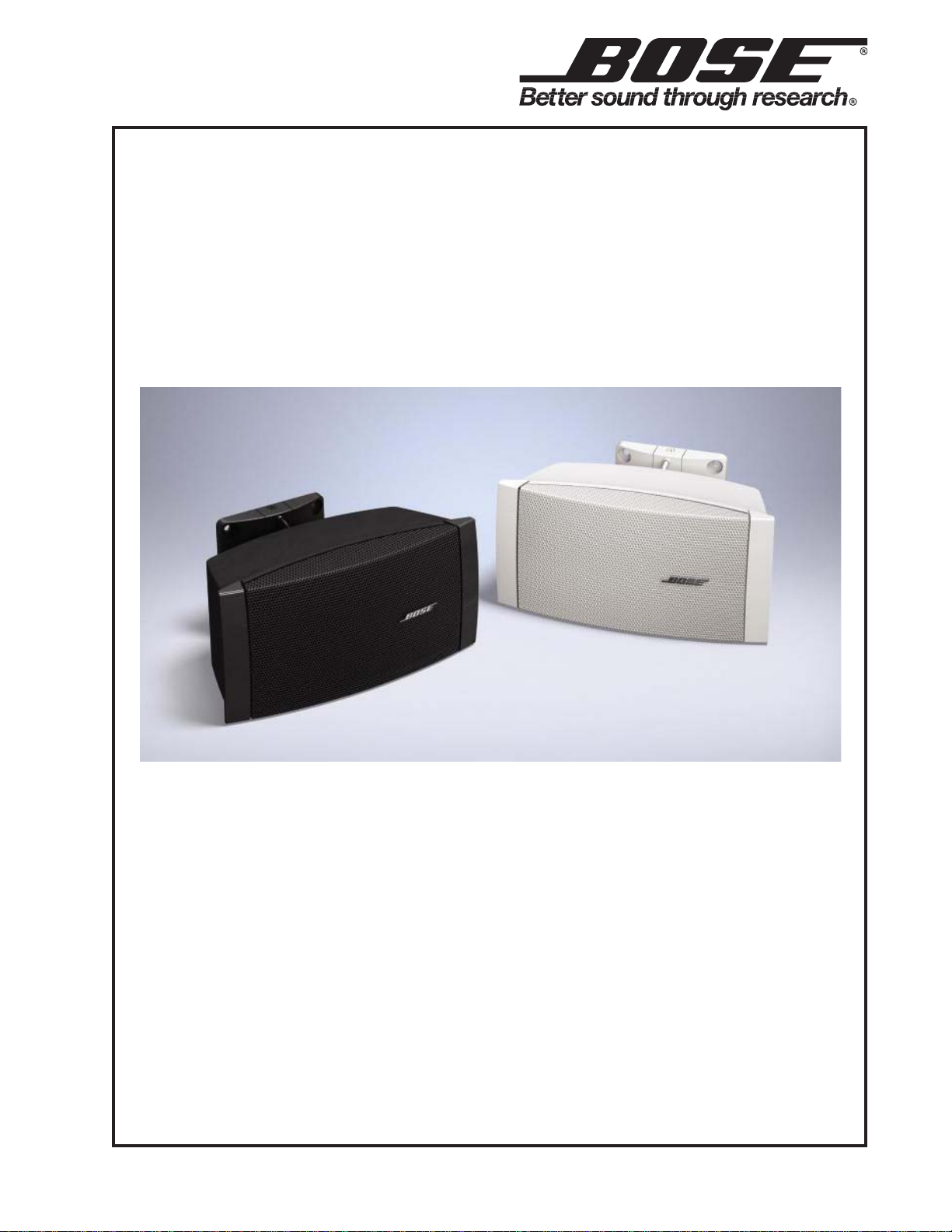
FreeSpace® DS 16S and DS 16SE
Loudspeakers
(Indoor and Outdoor Versions)
©2009 Bose Corporation
Service Manual
Reference Number 294951-SM Rev . 01
Page 2

CONTENTS
Warranty Information.........................................................................................................................2
Specifications....................................................................................................................................3
Product Description .........................................................................................................................4
Part List Notes ..................................................................................................................................4
Packaging List, FreeSpace
Figure 1. FreeSp ace DS 16S and DS 16SE Packaging View ..........................................................5
Main Part List, FreeSpace DS 16S Loudspeaker (Indoor Version) ............................................. 6
Figure 2. FreeSp ace DS 16S (Indoor V ersion) Exploded V iew.........................................................6
Main Part List, FreeSpace DS16 SE Loudspeaker (Outdoor Version) ........................................ 7
Figure 3. FreeSp ace DS 16SE (Outdoor Version) Exploded View ...................................................7
Main Part List, Basic Elevation Bracket (included with loudspeaker)........................................8
Figure 4. Basic Elevation Bracket Exploded View ............................................................................8
Disassembly Procedures .................................................................................................................9
Test Procedures .............................................................................................................................10
Figure 5. Loudspeaker Wiring Diagram .........................................................................................10
Service Manual Revision History .................................................................................................11
®
DS 16S and DS 16SE Loudspeakers ..............................................5
CAUTION: The Bose® FreeSpace® DS 16S and DS 16SE Loudspeakers
contain no user-serviceable parts. To prevent warranty infractions,
refer servicing to warranty service stations or factory service.
WARRANTY INFORMATION
The Bose FreeSpace DS 16S and DS 16SE Loudspeakers are covered by a
5-year transferable limited warranty .
PROPRIET ARY INFORMATION
THIS DOCUMENT CONT AINS PROPRIET ARY INFORMA TION OF
BOSE CORPORA TION WHICH IS BEING FURNISHED ONLY FOR
THE PURPOSE OF SERVICING THE IDENTIFIED BOSE PRODUCT
BY AN AUTHORIZED BOSE SERVICE CENTER OR OWNER OF
THE BOSE PRODUCT, AND SHALL NOT BE REPRODUCED OR
USED FOR ANY OTHER PURPOSE.
2
Page 3

SPECIFICATIONS
FreeSpace® Model DS 16S and DS 16SE Loudspeakers
Electrical
Loudspeaker Impedance: 8 ohms
Power Handling: 16 Watts
70V Transformer TAP Settings: 1, 2, 4, 8 and 16W
100V Transformer TAP Settings: 2, 4, 8 and 16W
Acoustical
Sensitivity: 84 dB SPL @1W/1m.
Maximum Sound Pressure Level: 96 dB SPL @ 1m (pink noise)
Frequency Range: 90Hz - 16kHz
Radiation Pattern: 90 degrees conical averaged from 1kHz to 6 kHz
Compression: < 3 dB with 32W watt sine wave
Distortion: < 30% at 32W sine wave
Port Noise: < -40dB (from fundamental)
Mechanical
Dimensions, Single Speaker: (W) 9.85 in x (D) 4.61 in x (H) 4.88 in
(250 mm x 117 mm x 124 mm)
Packed System: (W) 12.6 in x (D) 9.1 in x (H) 9.0 in
(320 mm x 231 mm x 229 mm)
System Weight: Single Speaker: 4.0 lbs (1.8 kg)
Packed System: 5.1 lbs (2.3 kg)
3
Page 4

PRODUCT DESCRIPTION
The FreeSpace® DS16 S and DS16 SE are the entry level surface-mount speakers for business
music applications. They consist of a single 2.25" driver in a rugged, plastic enclosure. There are
two variants of the DS16 Loudspeaker , an indoor version qualified for use where it is not exposed
to weather and an outdoor version qualified for use fully exposed to weather .
The indoor and outdoor variants are each available in two colors, black and white. They ship with
a basic bracket allowing for pitch adjustments. An upgraded bracket is available that allows the
speaker to be life safety compliant for the worldwide market. The upgraded bracket allows left to
right (yaw) adjustments in addition to up and down (pitch) adjustments. When used with the
upgraded bracket the surface mount DS16 loudspeaker is life safety compliant as described
below.
The DS 16S and DS 16SE have passed extensive testing and comply with the following specifications and uses:
LISTED to ANSI/UL 1480-2005
• Fire Protective Signaling Use – UL Category UUMW , File Number S 3241. Control Number
42S9 when installed with a junction box (on-wall or in-wall). Not for use with DC-supervised
systems.
• General Purpose Use – UL Category UEAY, File Number S 5591 Control Number 3N89.
• The DS 16SE is suitable for use outdoors in wet locations.
• The DS 16S is suitable for use indoors in damp locations.
• Suitable for installation using Class 1, Class 2, or Class 3 wiring methods in accordance with
NFP A 70, National Electric Code, 2002, Article 640.
• Suitable for use with fire alarm circuit wiring methods in accordance with NFPA 70, National
Electric Code, 2002, Article 760.
• EMC Directive 89/336/EEC and Article 10 (1) of the directive, EN50081-1 and EN50082-1 as
signified by the CE mark.
The DS 16S and DS 16SE also have been designed to the requirements defined in the following
European regulatory specification for combination systems:
• British Standard Code of Practice BS 5839, Part 8.
• T ested to IEC60268-5.
PART LIST NOTES
1. This part is not normally available from Customer Service. Approval from the Field Service
Manager is required before ordering.
2. The individual parts located on the PCBs are listed in the Electrical Part List.
3. This part is critical for safety purposes. Failure to use a substitute replacement with the
same safety characteristics as the recommended replacement part might create shock, fire
and/or other hazards.
4. This part is referenced for informational purposes only. It is not stocked as a repair part.
Refer to the next higher assembly for a replacement part.
4
Page 5

PACKAGING LIST
Item
Description Bose® Part
Qty. Note
FreeSp ace® DS 16S and DS 16SE Loudspeakers
Number
1 WALL MOUNT BRACKET, BLACK
WALL MOUNT BRACKET, WHITE
INCLUDES:
POLY BAG - 1 4
POLY BAG - 1 4
WASHER, M4, LOCK, SS - 2 4
SCREW, M4x60, PAN HEAD, SS - 1 4
SCREW, M4x20, SOCKET HEAD - 2 4
SCREW, M4x8, FLAT HEAD - 1 4
2 INSTALLATION GUIDE 299653 1
3 CARTON KIT, INCLUDES: 295900
CARTON SHEET - 1 4
POLY FOAM, EPS - 1 4
POLY BAG - 1 4
CARTON - 1 4
Number
295891-001
295891-002
1
Figure 1. FreeSpace DS 16S and DS 16SE Packaging View
5
Page 6

MAIN PART LIST
FreeSp ace® DS 16S Loudspeaker (Indoor Version)
Item
Number
1 GRILLE, INDOOR, BLACK
GRILLE, INDOOR, WHITE
INCLUDES:
BOSE LOGO ASSY, BLACK or
BOSE LOGO ASSY, WHITE
Description Bose® Part
Number
295896-001
295896-002
303039-001
303039-001
Vendor Part Number Qty. Note
SVC-AMOE11+GRILL
1
SVC-AMOE12+GRILL
-
2 DRIVER, 2.75” 298081 8900-3840+0 1
3 CAP, GRILLE, BLACK
CAP, GRILLE, WHITE
295897-001
295897-002
1467-7001+0
1467-7002+0
2
4 FRONT BAFFLE 295899-001 4155-1931+0 1 4
5 SCREW, TAPPING, M4X10 - 2954-4010+3000 10 4
6 XFMR/ROTARY SWITCH ASSY,
296602 SVC- AMOE11+TRANS 1
70/100V, 16W, 8 OHM
7 GASKET - 4149-0701+0 1
8 CABINET, REAR, BLACK
CABINET, REAR, WHITE
9 BRACKET, MOUNTING, BLACK
BRACKET, MOUNTING, WHITE
295895-001
295895-002
295892-001
295892-002
1467-6901+0
1467-6902+0
4155-1993+0
4155-1994+0
1 4
1
10 WIRE-CONN, 4P, P3.96, BLACK 295894-001 7012-7710+0 1
WIRE-CO NN, 4P, P3.96, WHITE 295894-002 7012-7711+0
11 SCREW, M4X14, BLACK - 2904-4014+3000 2 4
12 WASHER - 2600-4008+0783 2 4
13 GROMMET, RUBBER, BLACK 295893-001 4157-1071+0 1
14 ROTARY SWITCH - 5200-4933+0 1 4
15 TAP KNOB 295898-001 2447-3601+0 1
15 NUT, HEX, ROTARY SWITCH - - 1 4
16 SCREW, TAPPING, M3X10 - 2954-3010+3000 4 4
- BOSE LOGO ASSY, BLACK
BOSE LOGO ASSY, WHITE
INCLUDES:
CUP WASHER
SPRING
WASHER, SELF LOCKING
303039-001
303039-001
-
-
4159-0170+0
2510-3931+0
2610-4003+1207
1
4
4
4
10
7
3
2
1
16
4
5
15
5
6
5
14
8
9
13
12
11
Figure 2. FreeSpace DS 16S (Indoor Version) Exploded View
6
Page 7

MAIN PART LIST
FreeSp ace® DS16 SE Loudspeaker (Outdoor Version)
Item
Number
1 GRILLE, OUTDOOR, BLACK
GRILLE, OUTDOOR, WHITE
INCLUDES:
BOSE LOGO, BLACK or
BOSE LOGO, WHITE
Description Bose® Part
Number
298083-001
298083-002
303039-001
303039-002
Vendor Part Number Qty. Note
SVC-MOESO11+GRIL
1
SVC-MOESO12+GRIL
-
-
2 DRIVER, 2.75” 298082 8900-3830+0 1
3 CAP, GRILLE, BLACK
CAP, GRILLE, WHITE
295897-001
295897-002
1467-7001+0
1467-7002+0
2
4 FRONT BAFFLE 295899-001 4155-1931+0 1 4
5 SCREW, TAPPING, M4X10 - 2954-4010+3000 10 4
6 XFMR/ROTARY SWITCH ASSY,
296602 SVC-AMOE11+TRANS 1
70/100V, 16W, 8 OHM
7 GASKET - 4149-0701+0 1 4
8 CABINET, REAR, BLACK
CABINET, REAR, WHITE
9 BRACKET, MOUNTING, BLK
BRACKET, MOUNTING, WHT
295895-003
295895-004
295892-001
295892-002
1467-6903+0
1467-6904+0
4155-1993+0
4155-1994+0
1 4
1
10 WIRE-CONN, 4P, P3.96, BLK 295894-0 01 7012-771 0+0 1
WIRE-CONN, 4P, P3.96, WHT 295894-002 7012-7711+0
11 SCREW, M4X14, BLACK - 2904-4014+3000 2 4
12 WASHER - 2600-4008+0783 2 4
13 GROMMET, RUBBER, BLK 295893-001 4157-1071+0 1
14 ROTARY SWITCH - 5200-4933+0 1 4
15 TAP KNOB 295898-001 2447-3601+0 1
15 NUT, HEX, ROTARY SWITCH - - 1 4
16 SCREW, TAPPING, M3X10 - 2954-3010+3000 4 4
- BOSE LOGO ASSY, BLACK
BOSE LOGO ASSY, WHITE
INCLUDES:
CUP WASHER, PLASTIC
SPRING
WASHER, SELF LOCKING
303039-001
303039-002
-
-
-
-
-
2612-8520+1401
2510-3931+0
2610-4003+1203
1
4
4
4
10
7
3
2
1
16
4
5
15
5
6
5
14
8
9
13
12
11
Figure 3. FreeSpace DS 16SE (Outdoor Version) Exploded View
7
Page 8

MAIN PART LIST
Item
Description Vendor Part
Qty. Note
Basic Elevation Bracket (included with loudspeaker)
Number
1 WALL MOUNT, PC/ABS 4155-1981+0 1 4
2 SPEAKER MOUNT, PC/ABS 4155-1991+0 1 4
3 GROMMET, RUBBER SBR 4157-1071+0 1 4
4 CONNECTOR, 4-PIN, PVC 7012-7710+0 1 4
5 SCREW, M4x8mm, FLAT HEAD 2901-4008+3000 1 4
6 SCREW, M4x60mm, PAN HEAD, SEMS 2900-4060+3000 1 4
7 SCREW, 8-32, WITH SQUARE WASHER 2AZZ-0003+ZZZZ 6 4
8 TERMINAL, DOUBLE HOLE, BRASS 4135-6481+0 2 4
9 SCREW, M4x20mm, 4mm SOCKET HEAD 2900-4020+3000 2 4
10 WASHER, M4, LOCK 2600-4008+0783 2 4
11 BAG, POLY 1497-0032+0 1 4
12 TERMINAL, SINGLE HOLE, BRASS 4135-6491+1 2 4
13 WIRE, INSULATED, 18 AWG, UL1007, BLUE 1681-0060+A 1 4
14 WIRE, INSULATED, 18 AWG, UL1007, YELLOW
15 WIRE, INSULATED, 18 AWG, UL1007, WHITE 1681-0090+A 2 4
16 CABLE TIE, 2.6x120mm 6360-1341+0 1 4
17 NUT, HEX, M4 2640-4030+0703 1 4
Number
1681-0040+A 1 4
Figure 4. Basic Elevation Bracket Exploded View
8
Page 9

DISASSEMBLY PROCEDURES
Note: Refer to Figures 2 and 3 for the
following procedures.
1. Grille Removal
1.1 Remove the two grille end caps (3) by
grasping them and pulling them straight
away from the grille (1), off to the sides. This
will expose the grille mounting screws (16).
1.2 Using a Phillips-head screwdriver , remove the four screws that secure the grille to
the cabinet. Lift off the grille. Take care to not
lose the four washers located under the grille
tabs, if they are present.
2. Logo Removal
2.1 Remove the grille using procedure 1
above.
2.2 On the back of the grille (1), carefully remove the slotted washer that retains the
spring and spacer against the back of the
grille. Note the direction the spacer faces.
Slide the spring and spacer off of the logo
post.
4. Front Baffle Removal
4.1 Perform procedure 1.
4.2 Remove the four screws (5) that secure
the front baffle (4) to the rear cabinet (8).
4.3 Lift off the front baffle.
5. Transformer/Rot ary Switch Assembly
Removal
5.1 Perform procedure 4.
5.2 Using a flat-head screwdriver, carefully
pry the tap knob (15) off of the front baffle (4).
Lift off the knob.
5.3 Using a 1/2" nut driver, remove the hex
nut that secures the rotary switch (14) to the
front baffle.
5.4 Disconnect the two Faston connectors
from the driver.
5.5 Slide the wiring harness (10) through the
rubber grommet (13).
3. Driver Removal
3.1 Perform procedure 1.
3.2 Remove the four screws (5) that secure
the driver (2) to the front baffle (4).
3.3 Lift out the driver and disconnect the two
Faston connectors from the driver.
5.6 Remove the two screws (5) that secure
the transformer (6) to the rear cabinet (8).
9
Page 10

TEST PROCEDURES
1. Air Leak Test
1.1 Remove the right-hand grille cap to gain
access to the tap rotary switch. Set the
switch to the 8 Ohm setting.
1.2 Apply a 7 V rms, 95 Hz signal to the input
terminals of the loudspeaker.
1.3 Listen for any air leaks around the driver,
the rubber grommet located on the back of
the speaker and any seams. Reject any
speaker with an air leak. All rep airs must be
hidden. Replace any driver that has a rubbing
or ticking noise.
2. Rub and Tick Test
2.1 Remove the right-hand grille cap to gain
access to the tap rotary switch. Set the
switch to the 8 Ohm setting.
3. Power Sweep Test
3.1 Remove the right-hand grille cap to gain
access to the tap rotary switch. Set the
switch to the 8 Ohm setting.
3.2 Apply a 7 V rms, 50 Hz signal to the input
terminals of the loudspeaker.
3.3 Change the oscillator frequency slowly
from 50 Hz to 5 kHz. Listen for any buzzes,
rattles or other extraneous noises from the
driver or from the internal parts. The
whooshing noise from the port at around
95 Hz is acceptable.
Replace any driver that has a buzzing noise.
Ensure that there are no buzzes or rattles
from any internal parts.
4. Transformer Tap Select Test
2.2 Apply a 7 V rms, 95 Hz signal to the input
terminals of the loudspeaker.
2.3 At a dist ance of less than one foot, listen
for any extraneous sounds from the speaker.
Replace any driver that has a rubbing or
ticking noise.
Note: There is a normal suspension noise.
To distinguish between a rub or tick or
suspension noise, displace the cone slightly
with your finger. If the rubbing can be made
to go away or get worse, then it is a rub or a
tick. If the noise stays the same, it is a
suspension noise.
4.1 Remove the right-hand grille cap to gain
access to the tap rotary switch. Set the
switch to the 70V, 16W setting.
4.2 Apply a 70 V rms, 100 Hz signal to the
transformer input (70V/100V) of the loudspeaker.
4.3 Slowly change the tap selection from the
high position (16W) to the 2W position. A
decrease in level should be heard for each
descending tap.
Figure 5. Loudspeaker Wiring Diagram
10
Page 11

SERVICE MANUAL REVISION HISTORY
Date Revision
Description of Change Change Driven
Pages
Level
11/06 00 Document released at revision 00. Service manual
5/09 01 - Bracket vendor part number changes –
Item 9.
- Changed page order to match current
service manual format.
number change
By
initial release
Vendor part
Affected
All
6, 7
All
11
Page 12

SPECIFICATIONS AND FEATURES SUBJECT TO CHANGE WITHOUT NOTICE
Bose Corporation
The Mountain
Framingham Massachusetts USA 01701
Reference Number 294951-SM Rev . 01 5/2009 (P)
http://serviceops.bose.com
 Loading...