

Page 1
Bose® FreeSpace
®
360P Series II Environmental Speaker
Product Description
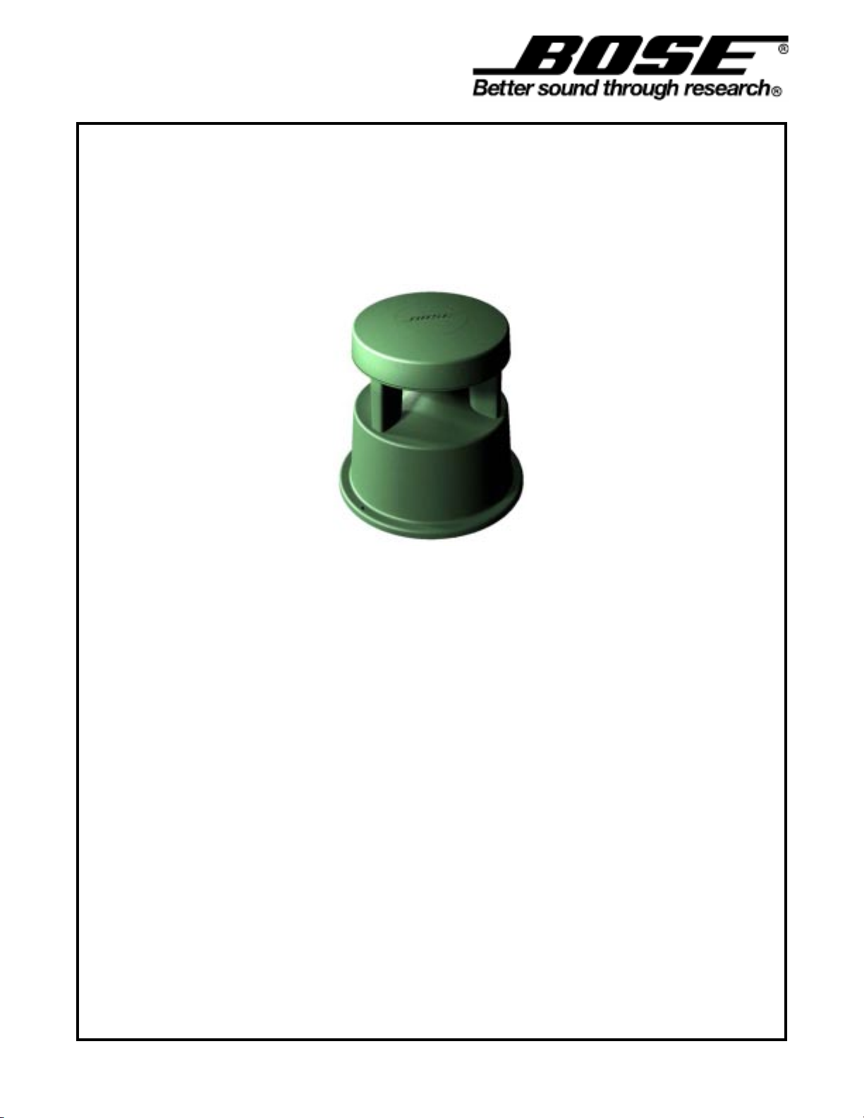
The Bose FreeSpace 360P loudspeaker is an 80-watt, full-range environmental loudspeaker with a
360° horizontal dispersion. It is designed for use with standard amplifiers in a variety of applications,
such as shopping malls, outdoor restaurants, resorts and theme parks. It offers the following features:
• An environmental 4.5" (11.4 cm) Bose driver with passive equalization, providing high reliability
and high quality sound for outdoor applications
• A multi-tap line transformer that permits selection of tap settings of 10W, 20W, 40W, or 80W at
the 70V or 100V inputs)
• Freestanding design that blends with the landscaping and permits installation either in ground or
attached to a horizontal concrete or wood surface
Service Manual
©2007 Bose Corporation
Reference Number 263872-SM
REV 02
Electronic copy only
Page 2
FS360P II Environmental Loudspeaker
Contents
Specifications ..................................................................................................................................1
Assembly Part List ..........................................................................................................................2
Packaging Part List - Pair ...............................................................................................................2
Figure 1. Assembly and Packaging View...........................................................................................2
Disassembly Procedures................................................................................................................3
Figure 2. Schematic Diagram ............................................................................................................4
Test Procedures .............................................................................................................................. 4
Specifications
Frequency Range: 70Hz to15kHz (±3dB)
FreeSpace© 360P versions: 70V/100V (10W, 20W, 40W, 80W taps)
Sensitivity: 87dB-SPL @ 1W, 1m (pink noise)
Maximum Acoustic Output: 100dB-SPL @ 1m (pink noise)
Dispersion (–6dB point, average,1-4kHz): 360° horizontal; 50° vertical
Long-Term Power Handling: 40W continuous, 80W peak
Mechanical Specifications:
Dimensions: 14.5" (36.83 cm) base diameter; 14.9" (37.85 cm) height
Weight: 14.5 lb (16.58 kg)
Input Connections: External multi-wire cable with wire nuts included
Enclosure Construction: Glass reinforced polypropylene
Mounting Points: Three (3) #10 (M4) holes in base
Warranty
The Bose® FreeSpace® 360P Series II loudspeaker is covered by a 5-year, transferable limited warranty
Proprietary Information
THIS DOCUMENT CONTAINS PROPRIETARY INFORMATION OF BOSE
CORPORATION WHICH IS BEING FURNISHED ONLY FOR THE PURPOSE OF
SERVICING THE IDENTIFIED BOSE PRODUCT BY AN AUTHORIZED BOSE
SERVICE CENTER OR OWNER OF THE BOSE PRODUCT, AND SHALL NOT
BE REPRODUCED OR USED FOR ANY OTHER PURPOSE.
Caution: The FreeSpace loudspeaker contains no user serviceable parts. To prevent warranty infractions, refer servicing to warranty service centers or factory service.
1
Page 3
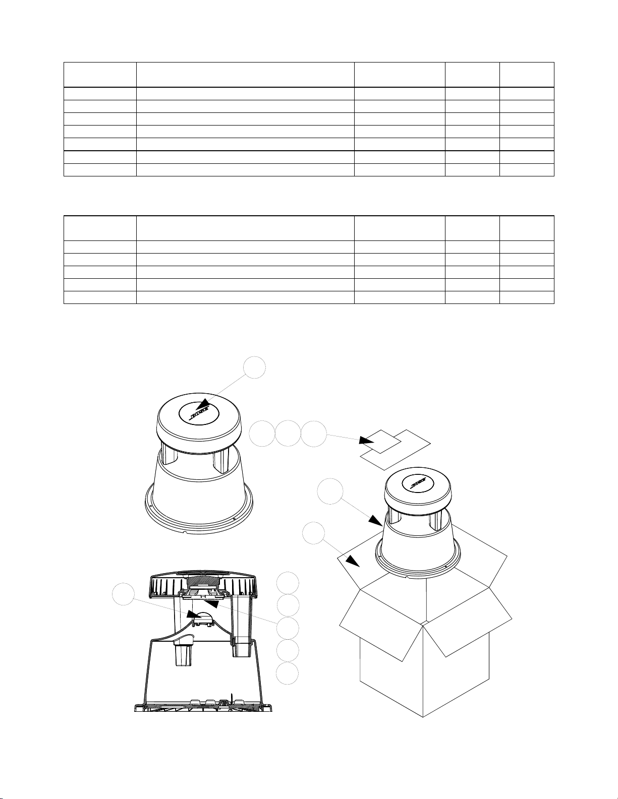
FS360P II Environmental Loudspeaker
Item
Description Part Number Qty Note
Item
Description Part Number Qty Note
Assembly Part List
Number
1 DRIVER ASSY, 4. 5", EN V 289807-001 1
2 GASKET, STRIP, 2. 0X 5. 0X340.0, PSA 291132-340 1
3 DIFFUSER, FS-5 1 268607 1
4 PROTECTO R, D RI VER, TRANSIT, 4. 5 120003 1
5 LOGO CAP, GREEN 268601-1 1
6 SCREW, TF, 8-11X1.25, HEXW HD 296497-020 3 4
7 SCREW, TAPP, 8-11X. 5, PAN, XREC/SQ 296495-008 3 4
Packaging Part List - Pair
Number
8 CARTON, REG SLO TTED 270555 1
9 OWNERS GUIDE 263873 1
10 CONNECTOR, WIRENUT, 16-22AWG 188199-001 8
11 BAG, POLY, ZIP LOC K, 2 MI L, 3X5" 260556-0305 1 4
12 BAG, POLY, 13X33.5X 11.5X3 137847 2 4
Note:
1. The crossover PCB is located in the top of the unit and is not accessible for repair or replacement.
2. The transformer is located in the base of the unit and is not accessible for repair or replacment.
3
5
9
10
1
2
4
6
11
12
8
Figure 1. Assembly and Packaging View
7
2
Page 4

Driver Removal
Top Cap Removal
FS360P II Environmental Loudspeaker
Disassembly Procedures
Cut the wires close to the driver terminal.Remove three screws then lift up driver.
Remove three screws.
Lift off diffuser.
Flip unit over. Lift off top cap.
Note:
1. The crossover PCB is located in the top of the unit
and is not accessible for repair or replacement.
2. The transformer is located in the base of the unit
and is not accessible for repair or replacement.
3
Page 5

FS360P II Environmental Loudspeaker
Test Procedures
Test SetUp
70V version: Apply the positive input signal to
the red wire and the negative to the black wire.
100V version: Apply the positive input signal to
the yellow wire and the negative to the black
wire.
Connect the orange (80W) tap wire to the white
wire. After testing, return the tap setting to what
the customer had set the unit to. See schematic diagram below.
1. Phase Test
1.1 Apply 8 Vdc to the speaker input terminal.
1.2 The driver should move outward.
2. Air Leak Test
2.1 Apply a 35 Vrms, 80 Hz signal to the
speaker input terminal. (Use 50 Vrms for 100V
units)
2.2 Listen for air leaks around the driver, top
cap, and base seams. Repairs can only be
made to the driver.
3. Rub and Tick Test
3.1 Apply a 35 Vrms, 10 Hz signal to the
speaker input terminal. (Use 50 Vrms for 100V
units)
3.2. No extraneous noises such as rubbing,
scraping or ticking should be heard. To distinguish between normal suspension noise, rubs
and ticks, displace the cone of the driver with
your finger. If the sound can be made to go
away or get worse, it’s a rub or tick and the
driver should be replaced. If the noise stays
the same, it’s normal suspension noise and
will not be heard with regular program material.
4. Sweep Test
4.1 Apply a 35 Vrms, 80 Hz signal to the
speaker input terminal. (Use 50 Vrms for 100V
units). Sweep the speaker from 80 Hz to 5
kHz.
4.2 Listen for buzzes, rattles or other extraneous noises from the driver or cabinet.
L1
70V
100V
COM
COM
80W
40W
20W
10W
RED
YELLOW
BLACK
WHITE
ORANGE
GREEN
VILOT
BLUE
CONNECTOR
R1 6.2 Ohm
C1 15uF
L1 1.5mH
R2 2.7 Ohm
C2 33uF
PINK
OR
BROWN
TRANSFORMER
100V
BLACK
R1
70V
PTC
C1 R2
80W
40W 20W 10W
C2
RED
+
-
BLACK
Note: The transformer and crossover components are not accessible for repair or replacement.
Figure 2. Schematic Diagram
4
Page 6

FS360P II Environmental Loudspeaker
Date Revision
Description of Change Change
Pages
Service Manual Revision History
Level
04/03 00
04/06 00 to 01 Added RoHS part numbers This product is
03/07 02 Added driver from strip –
1
Document released at
revision 00.
removed non-rohs driver
Driven By
now built with
RoHS
compliant
parts.
ECN 37167
Affected
3
5
Page 7

Specifications and Features Subject to Change Without Notice
Bose Corporation
The Mountain
Framingham Massachusetts USA 01701
P/N 263872 REV. 03 03/07 (P)
http://serviceops.bose.com
 Loading...