

Page 1
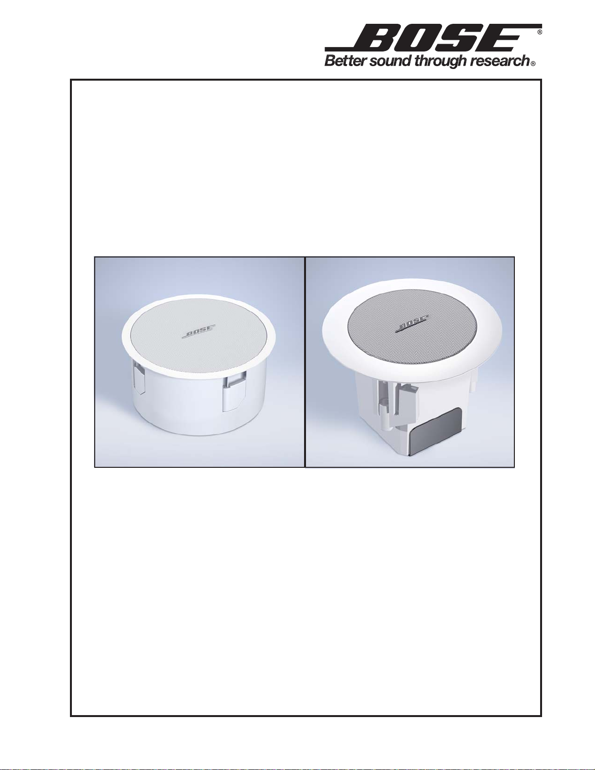
FreeSpace® 3 Series II
Loudspeaker System
FS3B Acoustimass® Bass Module FS3F Satellite Speaker
©2008 Bose Corporation
Service Manual
Part Number 263851 Rev . 02
Page 2

CONTENTS
Warranty Information.........................................................................................................................1
Specifications....................................................................................................................................2
Product Description .........................................................................................................................2
Disassembly Procedures .................................................................................................................3
FreeSpace® 3B Acoustimass® Bass Module Procedures...........................................................3
FreeSpace 3F Satellite Procedures ...............................................................................................3
Test Setup Procedures ................................................................................................................ 4-5
Figure 1. 6 Ohm Mono Test Setup Setting ........................................................................................4
Figure 2. Stereo Test Setup Setting ..................................................................................................4
Figure 3. Factory Default Setting ......................................................................................................5
Figure 4. 70/100 Volt Test Setup Setting ...........................................................................................5
Test Procedures ...............................................................................................................................6
Main Part List, FreeSpace 3 Series II Acoustimass® Module Loudspeaker ..............................7
Figure 5. FreeSp ace Series II Acoustimass Loudspeaker Exploded View ........................................7
Electrical Part List, FreeSpace 3B Crossover PCB ...................................................................... 8
Main Part List, FreeSpace 3F Satellite Speaker ............................................................................ 9
Figure 6. FreeSp ace 3F Satellite S peaker Exploded View ................................................................9
Packing List, FreeSpace 3 Series II Acoustimass® Module Loudspeaker ...............................10
Figure 7. FreeSp ace Series II Acoustimass Loudspeaker Packaging View ....................................10
Packing List, FreeSpace 3 Omni Loudspeaker Bracket.............................................................11
Figure 8. FreeSp ace 3 Omni Speaker Bracket Packaging View .....................................................11
Packing List, FreeSpace 3F Satellite Speaker ............................................................................ 12
Figure 9. FreeSpace 3F Satellite Speaker Packaging View ............................................................12
Figure 10. FreeSpace 3B Crossover PCB Schematic Diagram.....................................................13
Service Manual Revision History .................................................................................................14
CAUTION: The Bose® FreeSpace Series II Loudspeaker System
contains no user-serviceable parts. To prevent warranty infractions,
refer servicing to warranty service stations or factory service.
WARRANTY INFORMATION
The Bose FreeSp ace 3 Series II Acoustimass Module Loudspeaker and Free Sp ace Model 3F
Satellite Loudspeakers are covered by a 5-year transferable limited warranty .
PROPRIET ARY INFORMA TION
THIS DOCUMENT CONT AINS PROPRIET ARY INFORMA TION OF
BOSE CORPORA TION WHICH IS BEING FURNISHED ONLY FOR
THE PURPOSE OF SERVICING THE IDENTIFIED BOSE PRODUCT
BY AN AUTHORIZED BOSE SERVICE CENTER OR OWNER OF
THE BOSE PRODUCT, AND SHALL NOT BE REPRODUCED OR
USED FOR ANY OTHER PURPOSE.
2
Page 3

SPECIFICATIONS
System Components: Satellite: (1) 2 1/4" T widdlerTM in each FS3F satellite
Bass Module: (1) 5 1/4" Woofer in each bass module
External Dimensions: Satellite: 6.2 in. x 4.4 in. (157mm dia x 1 12mm depth)
Bass Module: 15.04 in. x 7.87 in. (382mm dia x 200 mm
depth)
Weight: Single Satellite: 1.65 lbs. (0.75 kg)
Bass Module: 15.4 lbs. (7 kg)
Packed System: 17.6 lbs. (8 kg)
Electrical Crossover: Frequency: 200 Hz @ 6 dB/octave
Impedance: 4 Ohms nominal 130 Ohms @ 70V, 32W, from 70 Hz - 15 kHz
250 Ohms @100V, 32W, from 70 Hz - 15 kHz
Power Handling: 100 Watts continuous per IEC-268-5, 96 hours.
Recommended amplifier / Max 100 Watts.
Filter: 24 dB/oct Butterworth,
Hi-pass 50 Hz
Lo-pass 250 Hz
Sensitivity: Satellites: >73 dB SPL, free field, per IEC-268-5
(1 W, 1m Free Space) (for octave-band centered at 400 Hz)
Bass Module: >74 dB SPL, free field, per IEC-268-5
(for octave-band centered at 100 Hz)
Flux Leakage: 2.0 Gauss max. @ 30mm from any surface of
(satellites) the satellite
System Protection: Polyswitch
PRODUCT DESCRIPTION
The Bose® FreeSpace® 3 Series II Acoustimass® Module Loudspeaker and the Bose FreeSp ace
3F satellite speakers are passive flush-mount ceiling speakers. Typical application is in retail,
restaurant, hospitality and other commercial applications. The Bose Free Space 3F satellite
speaker is a flush-mount variant of the current surface-mount Free Space 3 satellite.
3
Page 4

DISASSEMBLY PROCEDURES
FreeSpace® 3B Acoustimass® Bass Module
Procedures
Note: Refer to figure 5 for the following
procedures:
1. Grille and Logo Removal
1.1 Use force to pull out the logo (18), then
gently pull the grille (17) away from the baffle
(1). Be careful not to mark the surface of the
grille or the enclosure.
2. Woofer Assembly Removal
2.1 Use a cross-head screwdriver to remove
the 10 screws (10) that secure the rear
cover (3) to the enclosure (2). Gently turn
over the rear cover (3) to allow access to the
woofer assembly (5).
2.2 Remove 4 screws (9) of the woofer
assembly and 3 screws of the transformer
access cover (6). Lift out the transformer
access cover with the transformer (7)
attached to allow access to the crossover
PCB (19).
FreeSpace® 3F Satellite Procedures
Note: Refer to figure 6 for the following
procedures.
1. Grille Assembly Removal
1.1 Gently pull the grille assembly (4) away
from the enclosure (8). Be careful not to
mark the surface of the grille or the enclosure.
2. T widdlerTM Assembly Removal
2.1 Perform procedure 1.
2.2 Using a cross-head screwdriver, remove
the four screws (1) that secure the baffle
plate (9) to the enclosure (8).
2.3 Unplug the two wires from the driver (2).
Re-assembly Note: Be sure to observe
polarity when reconnecting the wires. Red
for "+" and black for "-".
2.3 Make a note of the wiring configuration
and unplug the four wires of the woofer
assembly from the crossover PCB.
2.4 Lift the woofer assembly out of the
enclosure.
3. Transformer Kit Removal
3.1 Perform step 2.1.
3.2 Remove the 3 screws of the transformer
access cover (6) and lift out the transformer
kit (6, 7, 8) from the mounting hole.
3.3 Make a note of the wiring configuration
and unplug all the wires from the transformer.
Re-assembly Note: Make sure the gap for
the transformer wires through the enclosure
is airtight.
4
Page 5
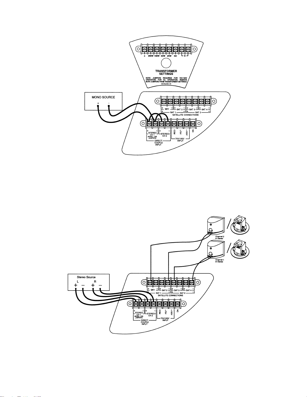
TEST SETUP PROCEDURES
Mono Direct: To bypass the transformer and prepare the loudspeaker for 6 Ohm use and mono
sound input, remove the two jumpers from the transformer settings on the front of the loudspeakers. Leave the CH1 and CH2 jumpers on the back of the loudspeaker as they are.
Figure 1. 6 Ohm Mono Test Setup Setting
Stereo Direct: To bypass the transformer and prepare the loudspeaker for 6 Ohm use and
stereo sound input, remove all the jumpers.
Figure 2. Stereo Test Setup Setting
5
Page 6

TEST SETUP PROCEDURES
Figure 3. Factory Default Setting
Note: Using the factory default settings, connect an amplifier output to either the 70 Volt or 100
Volt input connections as illustrated above.
Figure 4. 70/100 Volt Test Setup Setting
6
Page 7

TEST PROCEDURES
Note: The input voltage should be the actual
voltage present at the input and not the open
circuit generator output.
1. Bass Module Air Leak Test
Note: Connect the system as shown in
figure 1, 6 Ohm mono test setup settings.
1.1 Apply a 6 V rms, 50 Hz signal to the mono
input terminals of the bass module. Do not
connect the satellite speakers.
1.2 Listen carefully for air leaks from around
the terminal cup, port cap and cabinet
seams.
2. Woofer Phase Test
2.1 Apply a 6 Vrms, 50 Hz signal to both the
CH1 and CH2 stereo input terminals of the
bass module.
3.4 Reduce the input level to 3 Vrms.
3.5 Continue sweeping from 500 Hz to 15
kHz. Listen for a clean, undistorted output
from each satellite assembly. Replace any
satellite or woofer that buzzes or sounds
distorted.
4. 70/100 Volt Input Test Procedure
Note: This test is to ensure the transformer
is functioning. Connect the system as shown
in figure 4, 70/100V test setup settings.
4.1 Apply a 13 Vrms, 50 Hz signal to the bass
module at the 70 Volt input terminals.
4.2 Sweep the input frequency from 50 Hz to
500 Hz.
4.3 Apply a 13 V rms, 50 Hz signal to the 100
Volt input terminals.
2.2 While the signal is being applied to the
bass module, remove the input to one of the
stereo terminals.
2.3 The sound output level should drop by
approximately half. If the sound output level
increases, stays the same, or stops completely , then there is a wiring problem at the
crossover PCB or woofer.
3. System Sweep Test
3.1 Connect the system as shown in figure
2, stereo test setup settings.
3.2 Apply a 6 V rms, 10 Hz signal to the
stereo input terminals of the bass module.
3.3 While listening to the output of the system, sweep the input frequency slowly from
10 Hz to 500 Hz. The output should cross
over from the bass module to the satellite
speakers.
4.4 Sweep the input frequency from 50 Hz to
500 Hz.
Note: If the crossover or any components
on the crossover PCB are found to be
defective, replace the entire crossover PCB.
Note: A whooshing noise from the bass
module port at around 40 Hz and 160 Hz to
180 Hz is acceptable.
7
Page 8

MAIN PART LIST
Item
Description Part Number Qty.
Note
FreeSp ace® 3 Series II Acoustimass® Module Loudspeaker
Number
1 Baffle, FS3B Series II, Black
Baffle, FS3B Series II, White
2 Enclosure, FS3B Series II, Black
Enclosure, FS3B Series II, White
3 Rear Cover 303862 1
4 Junction Box Cover 303863 1
5 Woofer Assembly 303864 1
6 Transformer Access Cover 303865 1
7 Transformer, 70/100V, 100W 303866 1
8 Gasket for Transformer Cover - 1
9 Screw, M4x12 - 6
10 Screw, M4x18 - 12
11 Screw, M5x62 - 4
12 Terminal, 8 position 303867 3
13 Screw, M6x12 2
14 Anchor, Black
Anchor, White
15 Port Flare, Black
Port Flare, White
16 Cover, Front, Black
Cover, Front, White
17 Grille, FS3B Series II, Black
Grille, FS3B Series II, White
18 Nameplate, Logo, Bla ck
Nameplate, Logo, White
19 Crossover Assembly 303877 1
- 1
- 1
303869
303870
- 1
303871
303872
303873
303874
303875
303876
4
1
1
1
Figure 5. FreeSpace Series II Acoustimass Loudspeaker Exploded View
8
Page 9

ELECTRICAL PART LIST
Reference
Description
Part Number
Note
Reference
Description
Part Number
Note
Reference
Description
Part Number
Note
Reference
Description
Part Number
Note
FreeSp ace® 3B Crossover PCB
Resistors
Designator
R11 5.1 Ohm, WW, 5 W, 10% 303897 4
R21 5.1 Ohm, WW, 5 W, 10% 303897 4
Capacitors
Designator
C10 100uF, EL, BP, 85C, 50V, 20% 303898 4
C11 10uF, EL, BP, 85C, 50V, 20% 303899 4
C20 100uF, EL, BP, 85C, 50V, 20% 303898 4
C21 10uF, EL, BP, 85C, 50V, 20% 303899 4
Inductors
Designator
L11 Inductor, 300uH 303900 4
L21 Inductor, 300uH 303900 4
Miscellaneous
Designator
PTC11 Polyswitch, 60V, RXE110 303901 4
PTC21 Polyswitch, 60V, RXE110 303901 4
9
Page 10

MAIN PART LIST
Item
Description
Part Number
Qty.
Note
FreeSp ace® 3F Satellite Speaker
Number
1 Screw, M4x12mm 303879 6
2 Twiddler® Assembly 303880 1
3 Screw, M3x75mm 303881 3
4 Grille Kit, Black (consists of):
Grille, FS3F, Black
Nameplate, Logo, Black
Clip, Retaining, Logo
Grille Kit, White (consists of):
Grille, FS3F, White
Nameplate, Logo, White
Clip, Retaining, Logo
5 Cover, Junction Box 303885 1
6 Anchor, Black
Anchor, White
7 Terminal, 2 position 303889 2
8 Enclosure, FS3F, Black
Enclosure, FS3F, White
9 Plate, Baffle, FS3F - 1
10 Shield, Paint 303890 1
303882
-
-
-
303884
-
-
-
303887
303888
-
-
1
3
1
Figure 6. FreeSpace 3F Satellite Speaker Exploded View
10
Page 11

PACKING LIST
Item
Description
®®®®
Vendor Part
Qty. Note
FreeSp ace® 3 Series II Acoustimass® Module Loudspeaker
Bose
Number
Part
Number
Number
1 Carton, FS3B Series II 263585 1436-0501-1-2 1
2 Inner Pad A 263876 1450-6290-1 1
3 Inner Pad C 263878 1450-6430-0 1
4 FS3 Series II Loudspeaker, White
FS3 Series II Loudspeaker, White
-
-
BS030C
BS031C
1
5 Inner Pad B 263877 1450- 6330-1 1
6 Nameplate, Logo 263586 4154-5001-0 1
7 Grille, Black
Grille, White
263567-001
263567-002
4135-2271-0
4135-2272-0
1
8 Owner’s Manual 263579 4301-7016-0 1
Figure 7. FreeSpace Series II Acoustimass Loudspeaker Packaging View
11
Page 12

PACKING LIST
Item
Description Part
Qty Note
FreeSp ace® 3 Omni Loudspeaker Bracket
Number
Number
1 CARTON - 1 4
2 INSERT, CARDBOARD - 4 4
3 BRACKET, SAT ELLI TE, OMNIMOUNT, BLACK 282615-001 4
BRACKET, SATELLITE, O M NIMOUNT, ARTIC
282615-002 4
WHT
4 SCREW, M4x0.7x10MM, PAN HEAD, STAINLESS - 4 4
5 WASHER, M4, 9.8x4.5x 1. 0, STAINLESS - 4 4
6 COVER, OMNIMOUNT, BLACK 282614-0 0 1 1
COVE R, O MNIMOUNT, ARTIC WHT 282614-002 1
7 SHEET, INSTRUCTION 283942 1
8 BAG, POLY - 3 4
9 HARNESS, WIRE, O M NIMOUNT, BLACK 282617-001 1
HARN ES S, WIRE, OMNIMOUNT, A RTIC WHT 282617-002 1
10 EYEBOLT, FORGED, SHOULDER, M6x1, 12MM
- 3 4
LONG SHANK, 21 0 KG WORKING LOAD
11 HARNESS, CABLE, OMNIMOUNT, FS3B 282909 1
12 WASHER, M6, 12.7x6.8x1.0, STAINLESS - 6 4
13 SCREW, M5x0.8x12MM, HEX HEAD, STAINLESS - 4 4
9
13
65
4X
15
1
8
12
4
1232
14
7
12
4
10
Figure 8. FreeSpace 3 Omni Speaker Bracket Packaging View
12
Page 13

PACKING LIST
Item
Description
®®®®
Vendor Part
Qty. per
Note
FreeSp ace® 3F Satellite Speaker
Bose
Number
Part
Number
Number
carton
1 Carton, FS3F 253811 1436-0301-0-2 1
2 FS3F Loudspeaker, Black
FS3F Loudspeaker, White
-
-
bs011c
bs010c
2
3 Inner Pad A 263791 1450- 6220- 1 1
4 Polybag - 1497-4742-0 2
5 Inner Pad B 263790 1450- 6210- 0 1
6 Polybag - 1497-1962-0 2
7 Grille Kit, Black
Grille Kit, White
263796
263797
svc-bs011c-grill
svc-bs010c-grill
2
8 CE Declaration Sheet - 3050-2321-1 1
9 Shield, Paint - 1450-6160-1 2
10 Carton Sheet 263792 1450-6230-0 2
Figure 9. FreeSpace 3F Satellite Speaker Packaging View
13
Page 14

Figure 10. FreeSpace
®
3B Crossover PCB Schematic Diagram
14
Page 15

Service Manual Revision History
Date Revision
Description of Change Change Driven
Pages
Level
11/02 00 Document released at revision 00. Service manual
5/05 01 Omnimount FS3B Bracket information
added
8/08 02 Added RoHS information RoHS 8-10
By
release
Accessory add 12
Affected
All
15
Page 16

SPECIFICATIONS AND FEATURES SUBJECT TO CHANGE WITHOUT NOTICE
Bose Corporation
The Mountain
Framingham Massachusetts USA 01701
P/N: 263851 Rev . 02 8/2008 (P) FOR TECHNICAL ASSIST ANCE OR P ART ORDERS, CALL 1-800-233-4408
http://serviceops.bose.com
 Loading...