

Page 1

The Bose® 251TM Environmental Speakers
OwOOwner
Owner’ s Guide
October 30, 2001
AM250811_04_V.pdf
ltkje
Page 2
For your records…
Serial numbers are located on the label on the back of each 251TM environmental speaker.
Serial numbers: and
Dealer name:
Dealer phone: Purchase date:
We suggest you keep your sales slip and warranty card together with this owner’s guide.
DECLARATION OF CONFORMITY
We, the offerer:
Bose® Corporation, The Mountain, Framingham, MA 01701-9168 USA
acknowledge our sole responsibility, that the product:
Kind of equipment: Loudspeaker
Type designation: 251TM Environmental Speakers
in accordance with EMC Directive 89/336/EEC and Article 10(1) of the
Directive, is in compliance with the following norm(s) or document(s):
Technical regulations: EN50081-1, EN50082-1
Accredited by:
Bose Corporation, The Mountain, Framingham, MA 01701-9168 USA
15 Jan. 2000
Bose Products B.V.
Nijverheidstraat 8, 1135 GE Edam
The Netherlands
Manufacturer’s authorized EU
Nic Merks
Vice President Europe
representative
2 October 30, 2001 AM250811_04_V.pdf
Page 3

Where to find…
Contents
Setting Up
Before you begin ........................................................................................................... 4
Unpacking the carton ................................................................................................... 4
Tools required ............................................................................................................... 4
Selecting the location for your speakers ...................................................................... 5
Installing Your 251TM Speakers
Choosing the speaker wire ........................................................................................... 6
Installing the mounting brackets ................................................................................... 6
Attaching the speakers to the brackets ........................................................................ 8
Making the connections................................................................................................ 9
Maintaining Your 251TM Speakers
Troubleshooting .......................................................................................................... 12
Warranty period .......................................................................................................... 12
Customer service ........................................................................................................ 12
Cleaning your speakers .............................................................................................. 12
Protecting the speaker wire ........................................................................................ 12
Product Information
Technical information.................................................................................................. 13
Bose® Corporation ....................................................................................inside back cover
AM250811_04_V.pdf October 30, 2001 3
Page 4
Setting Up
Before you begin…
Thank you for purchasing Bose® 251TM environmental speakers. These high-performance
outdoor speakers are engineered to provide sound quality far beyond that of other environmental speakers. The 251 environmental speakers are designed to withstand nature’s
elements – so you can be confident they will perform for years to come.
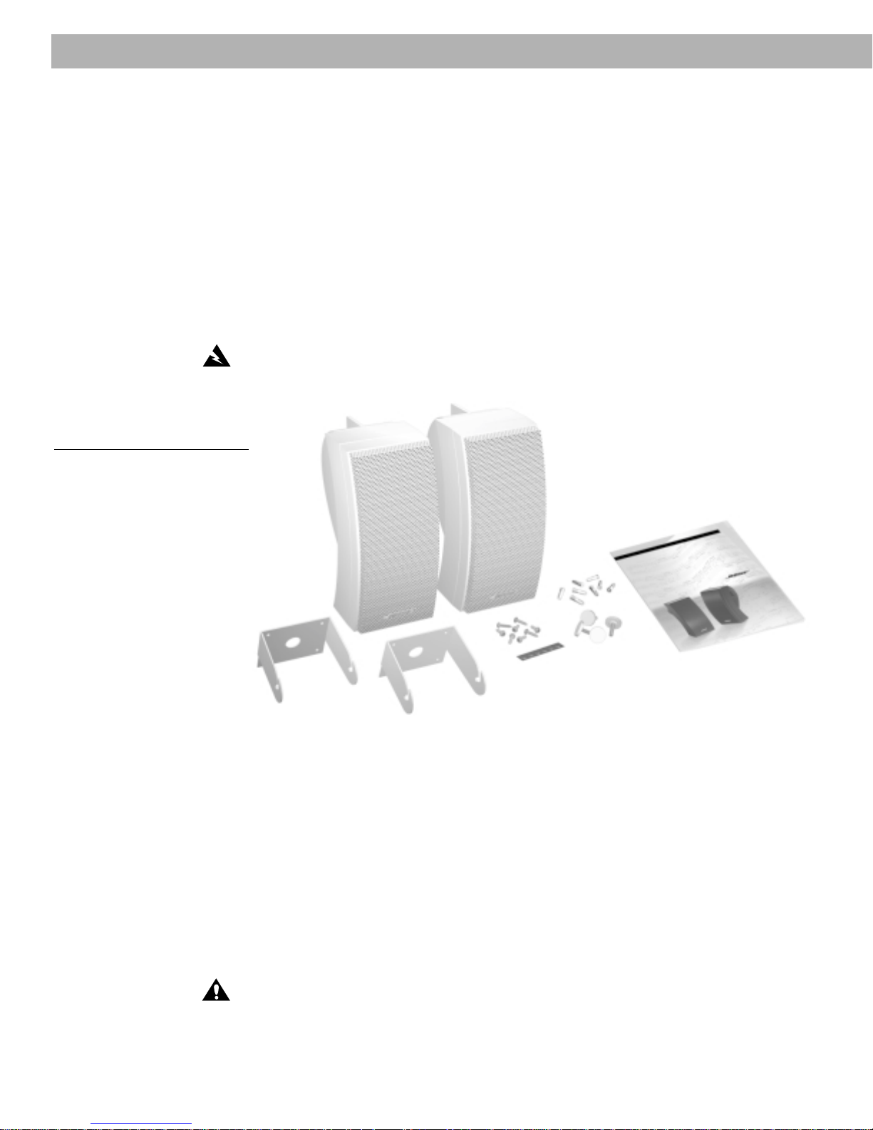
Unpacking the carton
Carefully unpack your speakers and save all packing materials for possible future use. Check
that your system contains the parts identified in Figure 1. Do not attempt to use your speakers if any part of them appears damaged. Instead, notify Bose Corporation or your authorized Bose dealer immediately.
Figure 1
Packaging contents:
• Two 251 speakers
• Two mounting brackets
• Mounting hardware (8 screws
and 8 plastic anchors)
• Six rubber feet
• Four knobs
• One owner's guide
T ools requir ed
WARNING:
To avoid danger of suffocation, keep the plastic bags out of the reach of
children.
You need the following items to complete this installation:
• Speaker wire (see “Wire recommendations” on page 13)
• Phillips-head screwdriver (#2)
• A drill with the following bits:
- A 3⁄32 inch diameter (2,5 mm) bit is preferred, or you can use a 1⁄8 inch diameter (3,0 mm)
bit. For concrete, a 1⁄
inch (6,0 mm) diameter masonry bit can be used.
4
• Eye and ear protection
• Dust mask
CAUTION:
speakers. If you are unsure of your ability to complete this process, consult a professional
installer. Please read this owner’s guide completely before beginning installation.
4 October 30, 2001 AM250811_04_V.pdf
Failure to follow the instructions in this owner’s guide voids all warranties on your
Page 5
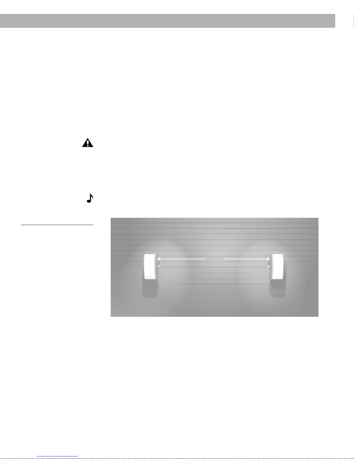
Selecting the location for your speakers
For best results, mount both speakers on the same wall, facing the listening area. Make sure
they do not face each other. (Outdoors, if you are not using an existing wall, consider the
length of your listening area as your “wall.”)
The 251TM speakers should be placed at least 7 feet (2 m) apart.
Please consider the following before mounting your speakers:
• Measure the length of speaker wire you need to connect each speaker to your receiver
or amplifier. To determine the wire gauge you will need, refer to the “Wire recom-
mendations” on page 13.
• It is important that the speaker wire not be tripped over, pinched, or pulled. Determine
the best route to protect the wire.
CAUTION:
concealed behind them, such as plumbing or electrical wire. If you are unsure about installing these speakers, contact a qualified professional installer.
• Regardless of where you place your speakers, make sure they cannot fall and cause
injuries.
• Bose® 251 speakers are not magnetically shielded. Keep them at least 9 inches (23 cm)
from any video screen or monitor.
Note:
If you are unsure about installing these speakers, contact a qualified professional installer.
Do not mount on surfaces that are not sturdy enough, or that have hazards
This product is not intended for use in areas where it will be subject to high vibration.
Setting Up
Figure 2
Speaker placement guidelines
7 ft (2 m)
minimum space between
speakers
AM250811_04_V.pdf October 30, 2001 5
Page 6

Installing Y our 251TM Speakers
Choosing the speaker wire
Be sure to use the proper gauge (thickness) of speaker wire. Standard zip cord (2-conductor,
18-gauge wire found at electrical and hardware stores) works for most applications. If your
speakers will be more than 30 feet (9 m) from the receiver or amplifier, see the “Wire recommendations” under “Technical Information” on page 13. Or check with your authorized Bose
dealer.
If you decide to run the speaker wire through a wall or underground, check your local building
code requirements, or contact an electrical installer before proceeding.
Note:
Be sure to cut enough wire to reach from the receiver to each speaker.
®
CAUTION:
Before making any connections, turn off your receiver or amplifier and unplug it
from the outlet (the AC power mains).
Installing the mounting brackets
The 251TM speakers should be mounted using the supplied brackets. They can be mounted
onto the exterior of a house or onto a deck railing or table. If you choose not to use the
supplied brackets, be sure to position your 251 speakers on a sturdy surface.
CAUTION:
ers. Vibration can cause the speakers to move, so it is important that you install the supplied
rubber feet before using the speakers on a surface. Refer to “Attaching the rubber feet” on
page 11.
Installing the brackets onto the exterior of a house
The 251 speakers should be mounted in a vertical position to achieve the best musical
performance. Figure 3 illustrates how the mounted speaker will look once the installation is
complete. To begin, mark four holes to indicate where you want to install the speaker bracket
(Figure 4). For wood, drill four starter holes using a 3⁄32 inch (2,5 mm) drill bit (Figure 5). For
cement, drill four starter holes using a 1⁄4 inch (6,0 mm) drill bit (Figure 5).
Figure 3
251 environmental speaker
mounted onto the exterior of a
house
If you do not use the supplied brackets, choose a level surface for the speak-
Figure 4
Marking four holes on the
exterior of a house
Figure 5
Drilling four holes on the
exterior of a house
6 October 30, 2001 AM250811_04_V.pdf
Page 7

Installing the mounting brackets (cont.)
Installing the brackets onto the exterior of a house (cont.)
For mounting onto wood, install the supplied screws using a Phillips-head screwdriver (Figure
6A). For concrete use, first install the supplied plastic inserts. Then, using a Phillips-head
screwdriver, install the screws (Figure 6B).
Installing Y our 251
TM
Speakers
Figures 6A and 6B
Installing the hardware
A. Wood
B. Concrete
Figure 7
251 environmental speaker
mounted onto a deck railing or
t
A. B.
3
⁄32 inch (2.25 mm)
1 1⁄2 inch (2.25 mm)
3
⁄32 inch (2.25 mm)
1
⁄2 inch (2.25 mm)
1
1
⁄4 inch (6.35 mm)
1
⁄2 inch (2.25 mm)
1
1
⁄4 inch (6.35 mm)
1 1⁄2 inch (2.25 mm)
Installing the brackets onto a deck railing or table
The 251TM speakers should be mounted in a vertical position to achieve the best musical
performance. Figure 7 illustrates how the mounted speaker will look once the installation is
complete. To begin, mark four holes to indicate where you want to install the speaker bracket
(Figure 8). Then, drill four starter holes using a 3⁄32 inch (2,5 mm) drill bit (Figure 9).
Figure 8
Marking four holes on a deck
railing or table
Figure 9
Drilling four holes on a deck
railing or table
AM250811_04_V.pdf October 30, 2001 7
Page 8

Installing Y our 251TM Speakers
Installing the mounting brackets (cont.)
Installing the brackets onto a deck railing or table (cont.)
Finally, install the four screws using a Phillips-head screwdriver (Figure 10).
Figure 10
Installing the bracket onto a
deck railing or table
Note:
If you are mounting your 251TM speakers on a deck railing or table, you will need to
rotate the Bose logo. Refer to “Rotating the Bose logo” on page 11 for instructions on how to
do this.
Attaching the speakers to the brackets
Once the brackets are installed, carefully follow these steps to attach the speakers to the
brackets. First, insert the knobs into each side of the speakers. Be sure to turn each knob
two full rotations (Figure 11). Then, carefully slide the speakers into the brackets (Figure 12).
Finally, temporarily tighten the speaker in a position that will allow you to easily connect the
speaker wire (Figures 13A and 13B).
Installing Y our 251™ Speakers
Figure 11
Installing the knobs
Figure 12
Sliding the speakers into the
brackets
two full rotations
8 October 30, 2001 AM250811_04_V.pdf
Page 9

Attaching the speakers to the brackets (cont.)
Installing Y our 251TM Speakers
Figures 13A and 13B
Temporarily tighten the
speakers to the brackets
A. Exterior of the house
B. Deck railing or table
A.
Making the connections
Preparing the speaker wire (not provided)
Speaker cord consists of two insulated wires. The insulation around one wire is striped,
collared, or ribbed. This marked wire is positive (+). The plain wire is negative (–). These
correspond to the red (+) and black (–) terminals on the back of the speaker, receiver, or
amplifier. Be sure to connect each wire to the proper terminal (positive to positive, negative
to negative).
Figure 14
Preparing the ends of each
wire
B.
Figures 15
Unscrewing the hex knob
1
⁄2 inch (1.3 cm)
At the ends of each cord, strip approximately 1⁄2 inch (1.3 cm) of insulation from both wires
(Figure 14). Next, twist the ends of each wire so there are no loose strands.
Connecting the speaker wire to the speakers
At the back of your speaker, unscrew the hex knobs on the terminal posts. This reveals a
small opening through each post (Figure 15). Using the wire guides, insert the marked wire
into the red (+) terminal. Then insert the plain wire into the black (–) terminal. Tighten the
knobs to secure the wires. See Figures 16A and 16B on page 10.
AM250811_04_V.pdf October 30, 2001 9
Page 10

Installing Y our 251TM Speakers
Attaching the speakers to the brackets (cont.)
Figures 16A & 16B
Connecting the speaker wire
A. Exterior of a house
B. Deck railing or table
A.
B.
Connecting the speaker wire to the receiver or amplifier
1. Connect the speakers on the left side of the listening area to the left channel of your
receiver or amplifier (Figure 17).
a. Attach the marked wire to the red (+) terminal.
b. Attach the plain wire to the black (–) terminal.
2. Connect the speaker on the right side of the listening area to the right channel of your
receiver or amplifier, following the same procedure above (Figure 17).
Note:
If your 251
receiver or amplifier, be sure to make the appropriate connections to the “B” channel.
TM
speakers are being connected as a secondary set of speakers to your
Figure 17
Connecting the speaker wire
Checking the connections
Check the speaker connections carefully. Make sure no loose strands of wire touch across
terminals. This could create short circuits that can damage an amplifier or receiver.
Tighten any loose connections before you plug in the receiver or amplifier.
T esting the connections
To make sure your speakers operate correctly, follow these steps:
1. Set the balance control on your receiver or amplifier to normal (centered).
2. Play some deep bass passages of music through the speakers.
The sound should seem to come from a point between the two speakers. The bass should
be full and natural. If not, your connections may be reversed, causing the speakers to play
out of phase. Refer to “Making the connections” on page 9. To correct the problem, make
sure all the wires are connected positive to positive (+ to +) and negative to negative (– to –).
Then repeat steps 1 and 2 to re-test the speakers.
10 October 30, 2001 AM250811_04_V.pdf
Page 11

Making the connections (cont.)
Putting the speakers in the final location
Loosen the knobs on each speaker to rotate the speakers into the desired position. Then,
tighten the knobs to secure the speaker in its final position (Figures 18A and 18B).
Installing Y our 251TM Speakers
Figures 18A and 18B
Putting the speaker in the final
position
A. Exterior of the house
B. Deck railing or table
Figure 19
Attaching the rubber feet
A.
B.
Attaching the rubber feet
If you do not plan to use the supplied brackets to mount your 251 environmental speakers,
you can place them on a sturdy, level surface. They should be standing in the vertical position. Be sure to attach the rubber feet before using your speakers. For proper balance be sure
to place the feet in the position shown in Figure 19.
Rotating the Bose logo
Mounting the speakers on a deck railing or table will require you to rotate the Bose logo.
Using your fingers, gently lift the logo, taking care not to detach it from the speaker, about 1⁄
inch (.24 cm) and turn it 180º.
Figure 20
Rotating the Bose logo
AM250811_04_V.pdf October 30, 2001 11
4
Page 12

Maintaining Y our 251
TM
Speakers
Troubleshooting
Problem What to do
Neither speaker plays • Check the settings on your receiver or amplifier. Refer to the owner’s guide that came with
it for instruction on settings.
• If your 251
amplifier, check that the connections have been made to the “B” terminals and that
the “B” speakers are selected to play.
The bass or treble is weak • Check the tonal balance setting on your receiver or amplifier.
Only one speaker plays • Check the balance control on your receiver or amplifier and make sure it’s centered.
• Check the wires connected to the speaker that does not play. Make sure the wires are in
good condition and are firmly connected. Review the “Making the connections” section on
page 9.
Only one speaker still plays • Disconnect the working speaker from the receiver or amplifier.
• Switch the cord of the “faulty” speaker from its original receiver or amplifier jacks to the
other set of jacks (the working speaker was originally attached to those jacks).
- If the speaker now works, the problem is in your receiver or amplifier. Reconnect your
speakers to a working unit.
- If there is still no sound from the speaker, continue below.
• Remove the cord from the working speaker and connect it to the “faulty” speaker.
- If the speaker now works, the problem was in the original speaker cord.
- If there is still no sound, the problem is in the speaker.
• If trouble persists, contact your authorized Bose® dealer, who will arrange for service. Or,
contact Bose customer service. See the inside back cover of this owner’s guide for a list of
phone numbers.
TM
speakers are connected as a second set of speakers to your receiver or
Warranty period
Bose 251 environmental speakers are covered by a limited five-year transferable warranty.
Details of coverage are on the warranty card that came with your speakers. Please fill out the
information section, detach, and mail it to Bose.
Customer service
For additional help in solving problems, contact Bose Customer Service. See the inside back
cover for offices and phone numbers.
Cleaning your speakers
Use a cloth dampened in mild detergent and water to remove dust or dirt from the outside of
your 251 speakers. Or use a hose to rinse them thoroughly with fresh water. Do not use
enough pressure to force water behind the grille and into the drivers or the acoustic ports.
Protecting the speaker wire
The bare ends of the speaker cord can be affected by exposure to the elements. This is
especially true of saltwater exposure. You may use a silicone caulking material, such as RTV
adhesive, to protect the connections. It is commonly available at hardware stores. If you do
use caulking, apply it only after the wires are connected and the knobs tightened down.
Check the connections annually, and reapply as needed.
12 October 30, 2001 AM250811_04_V.pdf
Page 13

Product Information
T echnical Information
Protective features
• Galvanized powder coated steel grille
• Environmentally resistant hardware
• Polymer fiber composite drivers
• Nickel-plated brass connection terminals
• Syncom® computer quality control
Driver complement
• Two (2) 21⁄2" environmental TwiddlerTM drivers per speaker
• One (1) 51⁄4" environmental woofer per speaker
Enclosure
• Dual-port molded polypropylene composite
• Black or white
Dimensions
•131⁄2" H x 53⁄4" W x 8" D (34.29 cm x 14.6 cm x 20.32 cm)
Compatibility
• Compatible with amplifiers or receivers rated 10-200 watts per channel/rated 4 to 8 ohms
• 100W IEC continuous power handling; rated 6 ohms
Environmental Capabilities
• Designed to withstand:
– salt fog, sun, high humidity (100%RH)
– temperature extremes (-40°F to 158°F; -40°C to 70°C)
Wire recommendations
• Based on a maximum frequency response deviation of ±0.5 dB
Gauge Length
18 (0.75 mm2) 30 ft (9 m) maximum
16 (1.5 mm2) 45 ft (14 m) maximum
14 (2.0 mm2) 70 ft (21 m) maximum
Weight
• 8 lb (3.63 kg) each
AM250811_04_V.pdf October 30, 2001 13
Page 14

14 October 30, 2001 AM250811_04_V.pdf
Page 15

Bose® Corporation
USA
Bose Corporation, The Mountain
Framingham, MA 01701-9168
1-800-367-4008
Phone hours - ET (eastern time):
Weekdays 8:30 a.m. to 8 p.m.
Saturdays 9 a.m. to 3 p.m.
Canada
Bose Ltd., 1-35 East Beaver Creek Road
Richmond Hill, Ontario L4B 1B3
1-800-465-2673
Phone hours - ET (eastern time):
Weekdays 9 a.m. to 5 p.m.
European Office
Bose Pr oducts B.V ., Nijver heidstraat 8
1135 GE Edam, Nederland
TEL 0299-390111 FAX 0299-390114
Australia
Bose Pty Limited, 1 Sorrell Street
Par ramatta NSW , 2150
TEL 02 9204-6111 FAX 02 9204-6122
Belgique/België
Bose N.V ., Limesweg 2, B-3700 T onger en
TEL 012-390800 F AX 012-390840
Danmark
Bose A/S, Industrivej 7, 2605 Brøndby
TEL 4343-7777 FAX 4343-7818
Italia
Bose S.p.A., V ia della Magliana 876
00148 Roma
www .bose.iT
TEL 06-65670802 FAX 06-65680167
Japan
Bose K.K., Shibuya YT Building
28-3 Maruyama-cho
Shibuya-ku, T okyo 150
TEL 3-5489-0955 FAX 3-5489-0592
Nederland
Bose B.V ., Nijver heidstraat 8
1135 GE Edam
TEL 0299-390111 FAX 0299-390109
Norge
Bose A/S, Solheimsgate 11
N-2001, Lillestrøm
TEL 63-817380 FAX 63-810819
Österreich
Bose Ges.m.b.H., V ienna Business Park W ienerber gstrasse 7
(10.OG)
A-1100 Vienna
TEL 01-60404340 FAX 01-604043423
Schweiz
Bose AG, Rünenber gerstrasse 13
4460-Gelterkinden
TEL 061-9815544 FAX 061-9815502
Deutschland
Bose GmbH, Max-Planck-Straße 36d
D-61381 Friedrichsdorf
TEL 06172-71040 FAX 06172-710419
France
Bose S.A., 6, r ue Saint V incent
78100 Saint Germain en Laye
TEL 01-30616363 FAX 01-30614105
India
Bose Corporation India Private Limited
W-16, Gr eater Kailash-II
New Delhi 110 048
TEL (011) 648 4462 FAX (011) 648 4463
Sverige
Bose A/S, Johannefr edsgatan 4
S-43153 Mölndal
TEL 31-878850 FAX 31-274891
United Kingdom
Bose Limited
1 Ambley Gr een
Gillingham Business Park
Gillingham, Kent ME8 ONJ
TEL 0870-741-4500 FAX 0870-741-4545
From other locations
Bose Customer Ser vice, 1 New Y ork A ve.
Framingham, MA 01701-9168 USA
TEL (508) 766-1900 FAX (508) 766-1919
Ireland
Bose Corporation
Carrickmacross, Co Monaghan
TEL (042) 9661988 FAX (042) 9661998
AM250811_04_V.pdf October 30, 2001 15
World Wide Web
www .bose.com
Page 16

© 2000 Bose Corporation, The Mountain
Framingham, MA 01701-9168 USA
250811 AM Rev.04 JN10679
16 October 30, 2001 AM250811_04_V.pdf
 Loading...