How it Works
Log In / Sign Up
Buy Points
How it Works
FAQ
Contact Us
Questions and Suggestions
Users
BOSE
Loading...
#
2
5
13
14
2
15
18
2.2
121
131
7
135
3
141
7
12 14SD
124797-B1
1401 II
141 Series II
151 BLACK
2
151 SE
10
151SE-2
151 WHITE
2
15 Series III
151
9
1600VI
8
1600VI SM
161 BLACK
161 SPEAKERS
3
161TM
161W
161
15
171
191
9
201
12
203
4
235
1201
1401
3
170310 SB1
172780 B2
1800 SM
1800V
12
191 SPEAKERS
2
1B
201II
2
201III
201 IV
2
201 Series
201 Series III
201 Series IV
201 Series V
201V
4
201 V DIRECT
201 V REFLECTING
203 SUPPLEMENT-S1
203 SUPPLEMENT-S2
2 14SD
2.2II
2.2 Series II
2 Series
2 Series II
1800
2
1800VI
10
1800V S2REV01
1800V S3
1800V S4
1800V S5
1800V S6
1800V S7
1800V-VI
3
1801
3
1978
1979
2000
2001
2150
11
2150 AC
2201
18370
21725
24643
2
24644
149393
2
161161
180520
181269
181812 B2
181816-S1
181816
183754
183757
183882
194101-B1
194101 B2
194101-S2
195571
250563
250564
17817686198
17817686228
17817697354
17817697361
17817700238
17817700351
Loading...
Loading...
Nothing found
180520
Schematic
2 pgs
113.52 Kb
0
Table of contents
Loading...
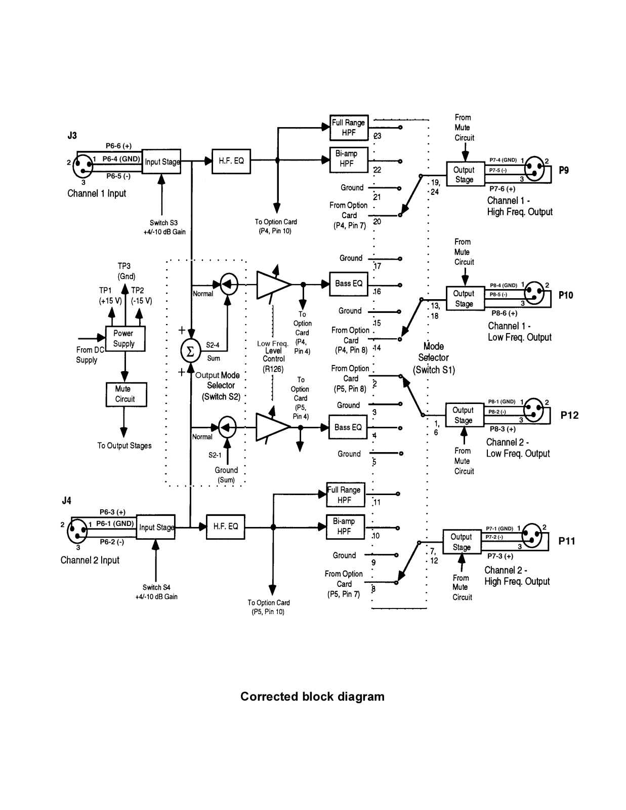
BOSE 180520 Schematic
...
BOSE Schematic
Download
Specifications and Main Features
Frequently Asked Questions
User Manual
Download
Page 1
Page 2
Loading...
+
hidden pages
Unhide
You need points to download manuals.
1 point = 1 manual.
You can buy points or you can get point for every manual you upload.
Buy points
Upload your manuals
 Loading...