

Page 1
Instruction Sheet
1600 VI and 1800 V/VI Amplifiers
ACM-1/Standard Input Module Installation
Follow the instructions below for dressing the ribbon cable when installing an ACM-1 or standard
input module into one of the above listed amplifiers.
1. Place the amplifier on a flat surface.
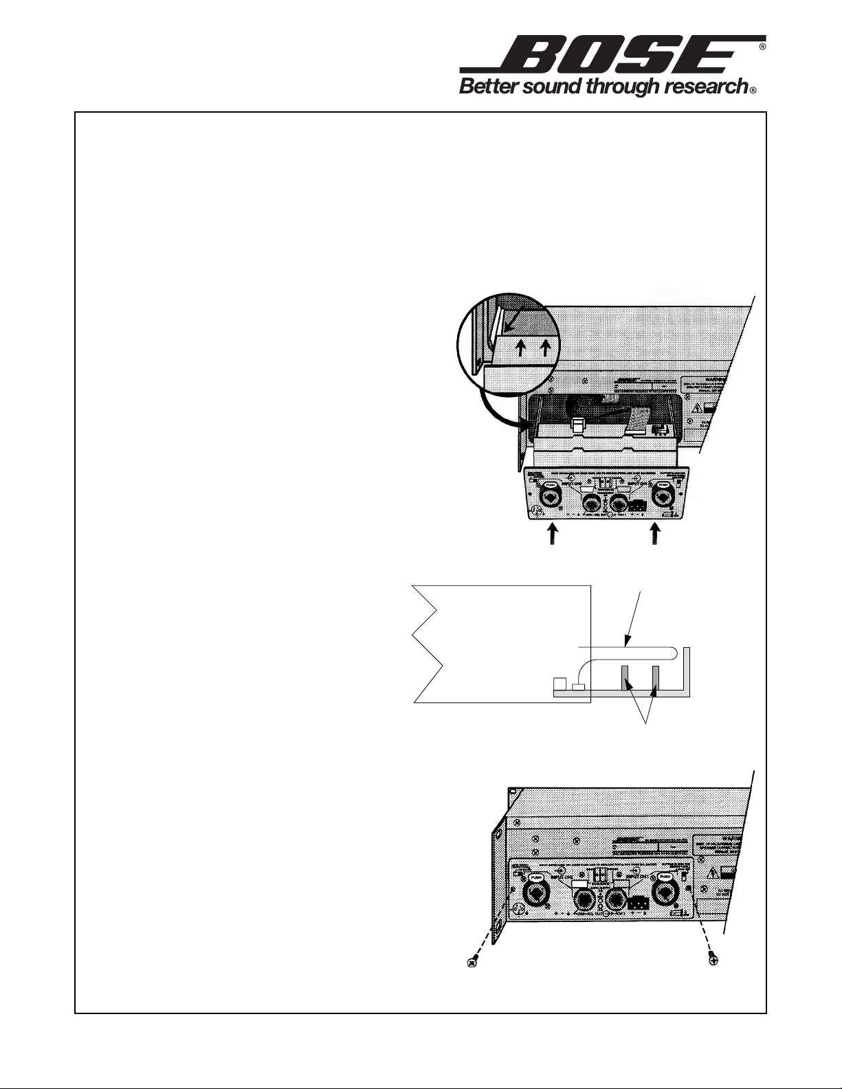
2. Slide the input module far enough into its slot
that you can connect the amplifier’s ribbon cable
to the input module’s J1 connector. Make sure the
red stripe on the ribbon cable is located at pin 1 of
the connector. If you are installing an ACM-1
module, there will be a second ribbon cable to
connect at J2. Align the ribbon cable’s red stripe
to pin 1 of the J2 connector.
3. Gently guide the ribbon cable up and over the
top of the input module PCB toward the input
module’s front panel. The ribbon cable must lie flat
over the EQ boards to avoid pinching it.
If this cable becomes pinched it will
cause improper amplifier operation.
4. While still guiding the ribbon cable,
slide the standard input module into the
amplifier opening until it is fully seated
and the input module is flush with the
amplifier rear panel. Be careful not to
pinch the ribbon cable between the input
module and the amplifier rear panel. Do
not allow the ribbon cable to bunch up in
front of the EQ cards as this will cause the EQ card
to be pushed out of position.
5. Secure the input module to the amplifier chassis
using two phillips-head screws.
ribbon cable
Cut away side
view of amplifier
Input
Module
EQ cards
CQE
Date Issued: 9/02
©
2002 Bose Corporation
Instruction Sheet
Part Number 199747-IS1 Rev. 00
 Loading...