

Page 1
FreeSpace® 360 Surface and In-ground
Loudspeaker EQ Cards
®
®
©
1998 Bose Corporation
Supplement
Part Number 181812-S7 Rev. 00
Page 2

CONTENTS
Electrostatic Discharge Sensitive (ESDS) Device Handling ........................................................ 3
Supplement Description.................................................................................................................. 3
Warranty Information....................................................................................................................... 3
Theory of Operation......................................................................................................................... 4
Equalizer Card Curve Diagrams ..................................................................................................... 5
Figure 1. FreeSpace 360® Surface EQ Curve.................................................................................. 5
Figure 2. FreeSpace 360 In-Ground Soft Ground EQ Curve ........................................................... 5
Figure 3. FreeSpace 360 In-Ground Hard Ground EQ Curve.......................................................... 5
Test Procedures ............................................................................................................................ 6-7
Part List Notes.................................................................................................................................. 8
FreeSpace 360 EQ Card Part List .............................................................................................. 9-10
Packing List, FreeSpace 360 EQ card (see Figure 4).................................................................. 11
Figure 4. FreeSpace 360 EQ Card Packing View.......................................................................... 11
Figure 5. FreeSpace 360 Equalizer Board Topside and Etch Layout Diagram.............................. 12
Figure 6. FreeSpace 360 Equalizer Board SMD and Etch Layout Diagram .................................. 12
CAUTION: The FreeSpace 360 Equalizer Cards
contain no user serviceable parts. To prevent
warranty infractions, refer servicing to
warranty service centers or factory service.
PROPRIETARY INFORMATION
THIS DOCUMENT CONTAINS PROPRIETARY INFORMATION OF
BOSE® CORPORATION WHICH IS BEING FURNISHED ONLY
FOR THE PURPOSE OF SERVICING THE IDENTIFIED BOSE
PRODUCT BY AN AUTHORIZED BOSE SERVICE CENTER OR
OWNER OF THE BOSE PRODUCT, AND SHALL NOT BE
REPRODUCED OR USED FOR ANY OTHER PURPOSE.
2
Page 3

ELECTROSTATIC DISCHARGE SENSITIVE
(ESDS) DEVICE HANDLING
This unit contains ESDS devices. We recommend the following precautions when repairing,
replacing, or transporting ESDS devices:
• Perform work at an electrically grounded work station.
• Wear wrist straps that connect to the station or heel straps that connect to conductive floor
mats.
• Avoid touching the leads or contacts of ESDS devices or PC boards even if properly
grounded. Handle boards by the edges only.
• Transport or store ESDS devices in ESD protective bags, bins, or totes. Do not insert
unprotected devices into materials such as plastic, polystyrene foam, clear plastic bags,
bubble wrap, or plastic trays.
SUPPLEMENT DESCRIPTION
This supplement should be used along with the 1800V EQ PCB service manual part number
181812-S2. The disassembly/assembly procedures, and packing part list should be used along
with the information in this manual. The test procedures were included in this manual for your
convenience.
WARRANTY INFORMATION
The FreeSpace® Model 360 Loudspeaker Equalizer Cards are covered by a 5-year
transferable limited warranty.
3
Page 4

THEORY OF OPERATION
These Equalizer cards are designed to be installed into the AmPlus™ 50 and 100 amplifiers
and the Bose® 1600 Series VI and 1800 Series V/VI amplifiers.
The FreeSpace® 360 loudspeaker requires equalization, and this equalization is a function of
the installation. There are two variants of the card that implement EQ curves for these
installation situations:
• In Ground (when the FreeSpace 360 loudspeaker is mounted in the ground).
The appropriate EQ curve for soft or hard ground is selected with a slide switch on the card.
When S1 is in the SOFT position, the Soft Ground EQ is used; when S1 is in the HARD
position, the Hard Ground EQ is used.
• In the Surface variant, S1 is omitted and jumpered to the SURFACE position.
Note: Refer to the FreeSpace 360 Surface or In-Ground schematic diagrams, as appropriate,
for the following explanation. The designators inside the brackets "[ ]" are the schematic grid
coordinates which are provided in order to make it easier to locate components on the
schematic sheet indicated in the description. Components shown on the schematic as
OPT (optional) are not used in that particular configuration.
The input signal is applied to these cards at JP1 pin 4. The first section at the input, U2-B [D7],
combines a first order high-pass filter with one section of a parametric cut filter. The parametric
is set for -15dB at 27Hz and provides a steep slope below about 80Hz. The equalization is
segmented, with one block (U2 and U1), all sections [D1-8] dedicated to bass region equalization. Following the output of this section, U2-A [D1], the signal is presented to two parallel
equalization paths, one comprised of U3 [B4-7], U4-B [C3], and dedicated to EQ for mounting
in soft ground of the FreeSpace 360 loudspeaker. The other path, comprised of U5 [B4-7],
U4-A [B3] provides equalization for the FreeSpace 360 loudspeaker in hard ground installations. In the case of the FreeSpace Surface EQ card, the bottom leg of the equalizer card is
not used.
The operation of all three equalizers is similar. Considering the bass equalizer, we see U2-B's
[D7] output passed through R8 [D7] and into the non-inverting input of U2-A [D2]. This input is
extended as a bus to which EQ sections Bass 1 [D6] and Bass 2 [D5] are connected. These
will introduce dips into the audio response to provide bass cut as required. Sections Bass 3
[D4] and Bass 4 [D3] are connected to a bus extended from the inverting input of U2-A [D2]
and provide bass boost.
See Figures 1,2 and 3 for the EQ curves for the various equalizer cards.
Each of the EQ sections utilizes a gyrator-connected op-amp in conjunction with a series
capacitance to simulate an LCR series tuned circuit. The values of the capacitors and resistors
are chosen to implement EQ dips and/or peaks at the appropriate frequency, amplitude and Q
to realize the desired EQ curves. On the In-Ground EQ card, S1 [B2] selects either the HARD
or the SOFT mount EQ curve.
The output signal is taken from JP1 pin 5, and returns to the amplifier. The equalizer cards are
sensed by the amplifiers as follows. In the AmPlus 50 and 100 amplifiers, Pin 12 of J1 [B2] is
grounded and is sensed by the dynamic EQ circuit on sheet 2 of the AmPlus 50 and 100
schematic diagrams. In the 1600/1800 amplifiers, the input module detects the presence of EQ
cards via J7-6 and J6-6. Without the card installed these pins are pulled high (+15V). This logic
high signal is also applied to the control pins of the switch ICs which selects the A
(unequalized) input. When an EQ is plugged into J7 and/or J6 pin 6, the EQ is detected and
pulls the control pin low (+7.5V), turning on the corresponding LED(s) and switching the IC to
the B input which will then select the output of the EQ card to be passed on to the amplifier.
4
Page 5

EQUALIZER CARD CURVE DIAGRAMS
Figure 1. FreeSpace® 360 Surface EQ Curve
Figure 2. FreeSpace 360 In-Ground Soft Ground EQ Curve
Figure 3. FreeSpace 360 In-Ground Hard Ground EQ Curve
5
Page 6

TEST PROCEDURES
FreeSpace® 360 In-Ground Loudspeaker
Test Setup Parameters:
1. Install the Equalizer card under test into
one of the Equalizer card jacks located on
the Input Module of the Bose® 1600 or
1800 Series amplifier, and perform the
following tests. Refer to the 1800V service
manual supplement part number 181812S2 for more information.
2. On the amplifier Input Module, place
switch SW1 to the NORM position. Place
switch S2 to the FULL BANDWIDTH
position.
3. The input voltage shall be the actual
input voltage present at the input, not the
open circuit generator input.
Note: Place the Hard/Soft switch S1 to the
SOFT position for the following tests.
1. In Soft Ground Equalizer PCB
Frequency Response Test
1.1 Apply a 100 mVrms, 1kHz signal to the
input jack of the amplifier channel under
test.
1.2 Adjust the amplifier volume controls to
maximum. No EQ card installed.
1.3 Reference a dB meter to the output of
the amplifier.
1.4 Shut off the amplifier and insert the EQ
card according to the assembly procedure.
In Soft Ground Frequency Response
Frequency Output Level
30 Hz -10.3 dB ± 1.5 dB
180 Hz +9.5 dB ± 1.5 dB
190 Hz +7.8 dB ± 1.5 dB
1000 Hz Reference
3000 Hz +8.1 dB ± 1.0 dB
4000 Hz +7.8 dB ± 1.0 dB
10000 Hz +16.4 dB ± 2.5 dB
1.7 Shut off the amplifier. Open the input
panel and switch the Hard/Soft switch to
the HARD position.
2. In Hard Ground Frequency
Response Test
2.1 Apply a 100 mVrms, 1kHz signal to the
input jack of the amplifier channel under
test.
2.2 Adjust the amplifier volume controls to
maximum. No EQ card installed.
2.3 Reference a dB meter to the output of
the amplifier.
2.4 Shut off the amplifier and insert the EQ
card according to the assembly procedure.
2.5 Turn on the amplifier and measure the
gain. There should be a -2.1 ± 1.0 dB
change in gain at the output.
2.6 Reference a dB meter and measure
the response according to the In Hard
Ground Frequency Response chart.
1.5 Turn on the amplifier and measure the
gain. There should be a 0.0 ± 1.0 dB
change in gain at the output.
1.6 Reference a dB meter and measure
the response of the EQ card according to
the In Soft Ground Frequency Response
chart.
In Hard Ground Frequency Response
Frequency Output Level
9 Hz +9.8 dB ± 1.5 dB
30 Hz -8.3 dB ± 1.5 dB
180 Hz +11.2 dB ± 1.0 dB
800 Hz +0.8 dB ± 1.0 dB
1000 Hz Reference
3000 Hz +8.1 dB ± 1.0 dB
4000 Hz +8.7 dB ± 1.0 dB
10000 Hz +18.2 dB ± 2.5 dB
6
Page 7

TEST PROCEDURES
3. Distortion Test
3.1 Apply a 780 mVrms, 1 kHz signal to the
input jack of the amplifier channel under
test.
3.2 Measure the distortion level at the
output of the amplifier. It should be ≤ 0.1%
THD.
FreeSpace® 360 Surface Loudspeaker
Test Setup Parameters
1. Install the Equalizer card under test into
one of the Equalizer card jacks located on
the Input Module of the Bose® 1600 or
1800 Series amplifier, and perform the
following tests. Refer to the 1800V service
manual supplement part number 181812S2 for more information.
2. On the amplifier Input Module, place
switch SW1 to the NORM position. Place
switch S2 to the FULL BANDWIDTH
position.
1.6 Reference a dB meter and measure
the response of the EQ card according to
the Surface Frequency Response chart.
Surface Frequency Response
Frequency Output Level
30 Hz -8.8 dB ± 1.5 dB
90 Hz +7.2 dB ± 1.5 dB
180 Hz +11.0 dB ± 1.5 dB
900 Hz +0.2 dB ± 1.5 dB
1000 Hz Reference
2000 Hz +0.4 dB ± 1.5 dB
5000 Hz +6.7 dB ± 1.0 dB
10000 Hz +17.9 dB ± 2.5 dB
2. Distortion Test
2.1 Apply a 780 mVrms, 1 kHz signal to the
input jack of the amplifier channel under
test.
2.2 Measure the distortion level at the
output of the amplifier. It should be ≤ 0.1%
THD.
3. The input voltage shall be the actual
input voltage present at the input, not the
open circuit generator input.
1. Surface Equalizer PCB Frequency
Response Test
1.1 Apply a 100 mVrms, 1kHz signal to the
input jack of the amplifier channel under
test.
1.2 Adjust the amplifier volume controls to
maximum. No EQ card installed.
1.3 Reference a dB meter to the output of
the amplifier.
1.4 Shut off the amplifier and insert the EQ
card according to the assembly procedure.
1.5 Turn on the amplifier and measure the
gain. There should be a +1.0 ± 1.0 dB
change in gain at the output.
7
Page 8

PART LIST NOTES
1. This part is not normally available from Customer Service. Approval from the Field Service
Manager is required before ordering.
2. The individual parts located on the PCBs are listed in the Electrical Part List.
3. This part is critical for safety purposes. Failure to use a substitute replacement with
the same safety characteristics as the recommended replacement part might create shock,
fire, and/or other hazards.
4. These parts are used on the FreeSpace® 360 in-ground EQ card only.
5. These parts are used on the FreeSpace 360 Surface EQ card only.
8
Page 9

FREESPACE® 360 EQ CARD PART LIST
Resistors
Reference
Designator
R1 2.00KΩ, CHIP, 0805, 1% 133625-2001
R2, 5, 12, 17,
18, 24, 26, 28,
30, 59, 64, 83,
89
R2, 5, 12, 17,
18, 23, 26, 59,
64
R3 18.2KΩ, CHIP, 0805, 1% 133625-1822
R4 1.50KΩ, 0805, 1/10W, 1% 133625-1501 5
R4 2.21KΩ, CHIP, 0805, 1/10W, 1% 133625-2211 4
R8, 21 200KΩ, 0805, 1/10W, 1% 133625-2003
R9, 10, 19, 20 392KΩ, 0805, 1/10W, 1% 133625-3923 5
R13, 14 28.7KΩ, 0805, 1/10W, 1% 133625-2872
R15, 16 127KΩ, 0805, 1/10W, 1% 133625-1273
R19, 20 169KΩ, 0805, 1/10W, 1% 133625-1693 4
R50, 63, 80, 93 24.9KΩ, CHIP, 0805, 1% 133625-2492
R51, 52 16.5KΩ, CHIP, 0805, 1% 133625-1652 5
R55, 56 10.0KΩ, CHIP, 0805, 1% 133625-1002 5
R55, 56 47.5KΩ, CHIP, 0805, 1% 133625-4752 4
R57, 58 5.76KΩ, CHIP, 0805, 1% 133625-5761 5
R57, 58, 87, 88 6.81KΩ, CHIP, 0805, 1% 133625-6811
R61, 62, 91, 92 4.87KΩ, CHIP, 0805, 1% 133625-4871 4
R81, 82, 51, 52 8.25KΩ, CHIP, 0805, 1/10W, 1% 133625-8251
R85, 86 66.5KΩ, 0805, 1/10W, 1% 133625-6652 4
R94 100Ω, CHIP, 0805, 1% 133625-1000
JUMPER, CHIP, 0805 133627 4
JUMPER, CHIP, 0805 133627 5
Description Part Number Note
Capacitors
Reference
Designator
C2 .22uF, BOX, 85, 50V, 5% 137127-224
C5, 56 390pF, MONO, COG, 50V, 5% 140564-391
C6 .018uF, BOX, 85, 100V, 5% 137127-183
C7 .0068uF, BOX, 85, 100V, 5% 137127-682 5
C7, 57, 87 .0068uF, BOX, 85, 100V, 5% 137127-682 4
C8 .047uF, BOX, 85, 63V, 5% 137127-473
C9, 10 .47uF, BOX, 85, 50V, 5% 137127-474 5
C11 .0015uF, BOX, 85, 100V, 5% 137127-152 4
C11 820pF, MONO, COG, 50V, 5% 140564-821 5
C12 .015uF, BOX, 85, 100V, 5% 137127-153 4
C12 .056uF, BOX, 85, 63V, 5% 137127-563 5
C13 .0018uF, BOX, 85, 100V, 5% 137127-182 5
C13, 81, 82 .022uF, BOX, 85, 100V, 5% 137127-223 4
C14 .0027uF, BOX, 85, 100V, 5% 137127-272 4
C14, 16 .001uF, BOX, 85, 100V, 5% 137127-102 5
C15, 51 .033uF, BOX, 85, 63V, 5% 137127-333
C16 .01uF, BOX, 85, 100V, 5% 137127-103 4
C17 18PF, 0805, 50V, 5% 133622-180 5
C50, 58, 88 .0056uF, BOX, 85, 100V, 5% 137127-562 4
C50, 61 .0033uF, BOX, 85, 100V, 5% 137127-332 5
Description Part Number Note
9
Page 10

FREESPACE® 360 EQ CARD PART LIST
Capacitors
Reference
Designator
C52 .068uF, BOX, 85, 63V, 5% 137127-683 4
C52, 60 .0047uF, BOX, 85, 100V, 5% 137127-472 5
C53 .0056uF, BOX, 85, 100V, 5% 137127-562 5
C53 270pF, MONO, COG, 50V, 5% 140564-271 4
C54 .0039uF, BOX, 85, 100V, 5% 137127-392 4
C54, 57, 58 .0082uF, BOX, 85, 100V, 5% 137127-822 5
C55 .0027uF, BOX, 85, 100V, 5% 137127-272 5
C56, 86 330pF, MONO, COG, 50V, 5% 140564-331 4
C59 560pF, MONO, COG, 50V, 5% 140564-561
C59, 89 560pF, MONO, COG, 50V, 5% 140564-561 4
C60, 90 .0047uF, BOX, 85, 100V, 5% 137127-472 4
C61, 91 .0033uF, BOX, 85, 100V, 5% 137127-332 4
C62, 92 68pF, 0805, COG, 50V, 5% 133622-680 5
C80 .0082uF, BOX, 85, 100V, 5% 137127-822 4
C83 220pF, MONO, 5% 140564-221 4
C84 .0022uF, BOX, 85, 100V, 5% 137127-222 4
C85 820pF, MONO, COG, 50V, 5% 140564-821 4
C98, 99 .1uF, 1206, Z5U, 50V, 20% 124958-1041 5
C100, 101, 102,
103, 104, 105,
106, 107, 108,
109
.022uF, 0805, X7R, 50V, 10% 133623-223 4
Description Part Number Note
Integrated Circuits
Reference
Designator
U1, 3, 5 0P AMP QUAD, SOIC-14, NJM2059 187472 4
U2, 4 OP AMP DUAL, SOIC-8, NJM4559 187473
Reference
Designator
JP1 CONN, HEADER, 12 PIN 149538
S1 JUMPER, CHIP 0805 133627 5
S1 SPDT, VERTICAL, SLIDE 187481 4
Description Part Number Note
Miscellaneous
Description Part Number Note
10
Page 11

PACKING LIST
FreeSpace® 360 EQ card (see Figure 4)
Item
Number
1 OWNER'S GUIDE, INST, EQ CARDS, PRO 191912 1
2 PCB ASSY, FS 360 SURFACE EQ CARD 196380 1
2 PCB ASSY, FS 360 IN-GROUND EQ CARD 196384 1
3 BAG, ANTISTATIC, 4 X 7.5 177761 1
4 TUBE, PACKING, ROUND, PLUG-SEAL 184177 1
5 CARTON, RSC, 9.63 X 7.88 X 6.63 178853 1
Description Part Number Qty. Note
1
2
3
REF (END CAP)
4
5
12 PACKAGED
EQ CARDS
PER CARTON
Figure 4. FreeSpace 360 EQ Card Packing View
11
Page 12

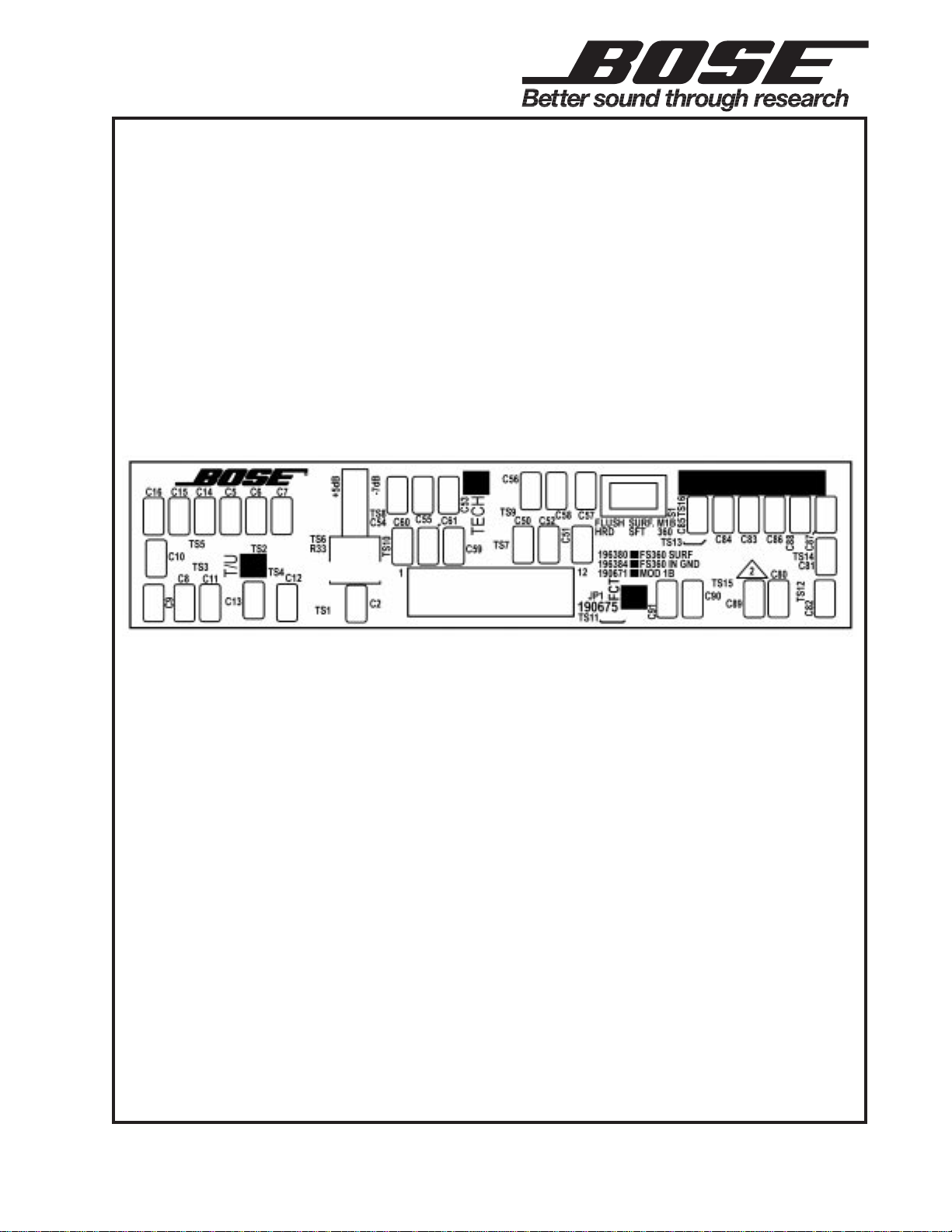
Figure 6. FreeSpace 360 Equalizer Board SMD and Etch Layout Diagram
Figure 5. FreeSpace
®
360 Equalizer Board Topside and Etch Layout Diagram
12
Page 13

SPECIFICATIONS AND FEATURES SUBJECT TO CHANGE WITHOUT NOTICE
®
®
Bose Corporation
The Mountain
Framingham, Massachusetts USA 01701
P/N: 181812-S7 Rev. 00 10/98 FOR TECHNICAL ASSISTANCE OR PART ORDERS, CALL 1-800-367-4008
 Loading...