

Page 1

Contents
Safety Information............................................................................................................................ 2
Electrostatic Discharge Sensitive (ESDS) Device Handling ........................................................ 3
Supplement Description.................................................................................................................. 3
Test Procedures ............................................................................................................................... 4
Part List Notes.................................................................................................................................. 5
Electrical Part List......................................................................................................................... 6-7
PCB Layout....................................................................................................................................... 8
Figure 1. PCB SMD Bottom View .................................................................................................... 8
Figure 2. PCB Component Top View................................................................................................ 8
Figure 3. Model 8 and Model 25/32 Schematic Diagram ................................................................. 9
CAUTION: THE EQ PCB ASSEMBLIES CONTAIN NO USER-SERVICEABLE PARTS. TO
PREVENT WARRANTY INFRACTIONS, REFER SERVICING TO WARRANTY SERVICE
STATIONS OR FACTORY SERVICE.
PROPRIETARY INFORMATION
THIS DOCUMENT CONTAINS PROPRIETARY INFORMATION OF
BOSE
®
CORPORATION WHICH IS BEING FURNISHED ONLY FOR
THE PURPOSE OF SERVICING THE IDENTIFIED BOSE PRODUCT
BY AN AUTHORIZED BOSE SERVICE CENTER OR OWNER OF THE
BOSE PRODUCT, AND SHALL NOT BE REPRODUCED OR USED
FOR ANY OTHER PURPOSE.
1
Page 2

SAFETY INFORMATION
1. Parts that have special safety characteristics are identified by the symbol on
schematics or by special notes on the parts list. Use only replacement parts that
have critical characteristics recommended by the manufacturer.
2. Make leakage current or resistance measurements to determine that exposed
parts are acceptably insulated from the supply circuit before returning the unit
to the customer. Use the following checks to perform these measurements:
A. Leakage Current Hot Check-With the unit completely reassembled, plug
the AC line cord directly into a 120V AC outlet. (Do not use an isolation
transformer during this test.) Use a leakage current tester or a metering
system that complies with American National Standards Institute (ANSI)
C101.1 “Leakage Current for Appliances” and Underwriters Laboratories
(UL) 1492 (71). With the unit AC switch first in the ON position, then in the
OFF position, measure from a known earth ground (metal water pipe,
conduit, etc.) to all exposed metal parts of the unit (antennas, handle bracket,
metal cabinet, screwheads, metallic overlays, control shafts, etc.), especially
any exposed metal parts that offer an electrical return path to the chassis.
Any current measured must not exceed 0.5 milliamp. Reverse the unit power
cord plug in the outlet and repeat test. ANY MEASUREMENTS NOT WITHIN
THE LIMITS SPECIFIED HEREIN INDICATE A POTENTIAL SHOCK HAZ ARD THAT MUST BE ELIMINATED BEFORE RETURNING THE UNIT TO
THE CUSTOMER.
B. Insulation Resistance Test Cold Check-(1) Unplug the power supply and
connect a jumper wire between the two prongs of the plug. (2) Turn on the
power switch of the unit. (3) Measure the resistance with an ohmmeter be-
tween the jumpered AC plug and each exposed metallic cabinet part on the
unit. When the exposed metallic part has a return path to the chassis, the
reading should be between 1 and 5.2 Megohms. When there is no return path
to the chassis, the reading must be “infinite”. If it is not within the limits specified,
there is the possibility of a shock hazard, and the unit must be repaired and re checked before it is returned to the customer.
2
Page 3

ELECTROSTATIC DISCHARGE SENSITIVE (ESDS)
DEVICE HANDLING
This unit contains ESDS devices. We recommend the following precautions when repairing,
replacing, or transporting ESDS devices:
• Perform work at an electrically grounded work station.
• Wear wrist straps that connect to the station or heel straps that connect to conductive floor
mats.
• Avoid touching the leads or contacts of ESDS devices or PC boards even if properly
grounded. Handle boards by the edges only.
• Transport or store ESDS devices in ESD protective bags, bins, or totes. Do not insert unprotected devices into materials such as plastic, polystyrene foam, clear plastic bags, bubble wrap
or plastic trays.
SUPPLEMENT DESCRIPTION
This supplement should be used along with the 1800V EQ PCB service manual part number
181812-S2. The disassembly/assembly procedures, and packing part list should be used along
with the information in this manual. The test procedures were included in this manual for your
convenience.
3
Page 4
TEST PROCEDURES
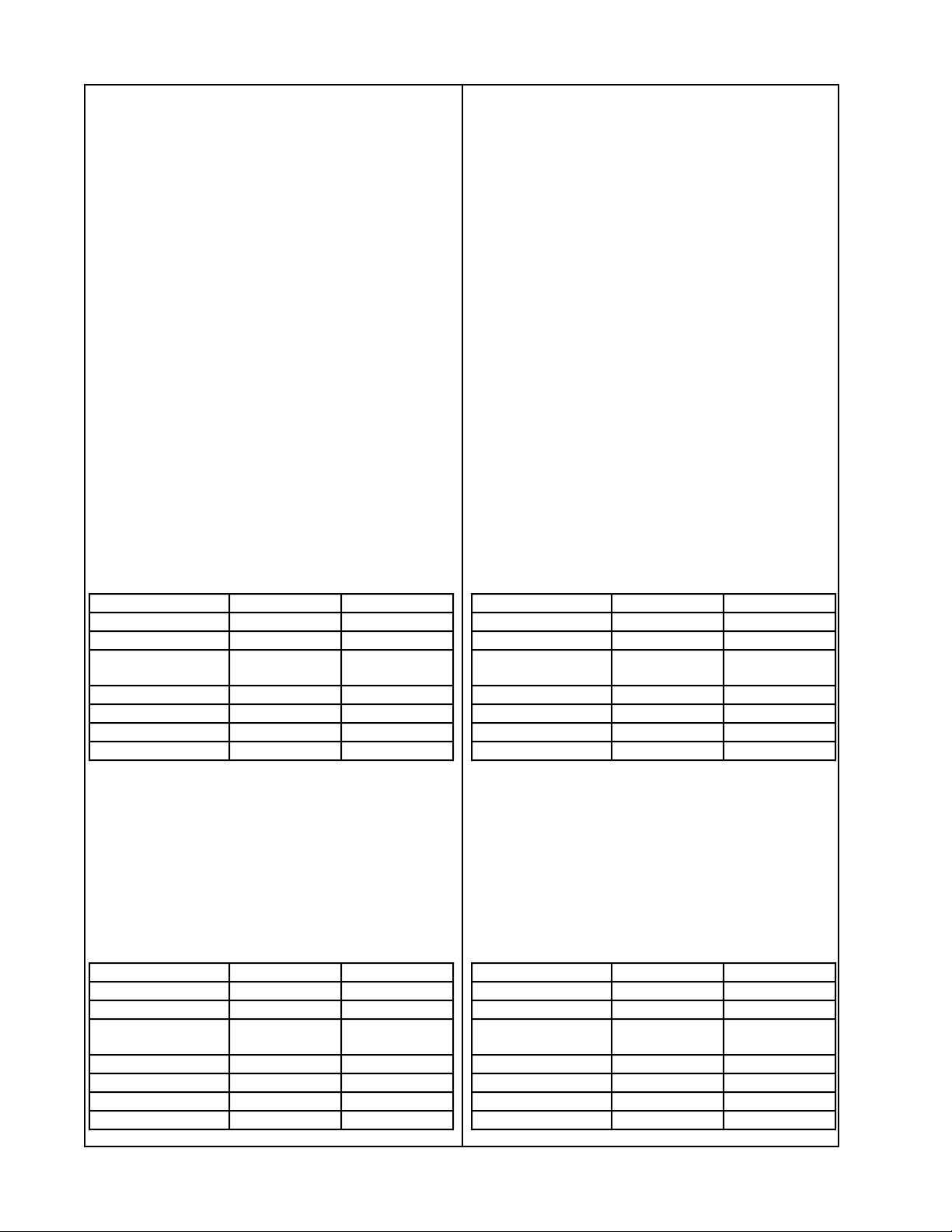
1. Model 8 EQ PCB Response Test
1.1 Apply a signal of 1kHz at an input level
of 100mVrms.
1.2 Adjust the amplifier volume controls to
maximum. No EQ card installed.
1.3 Reference a dB meter to the output of
the amplifier.
1.4 Shut off the amplifier and insert the EQ
card according to the assembly procedure.
1.5 Turn on the amplifier and measure the
gain. There should be a -3.5dB change in
gain at the output.
1.6 Reference a dB meter and measure
the response of the EQ card according to
the Model 8 Full Range Response chart
below.
Model 8 Full Range Response Chart Model 25/32 Full Range Response Chart
Frequency Output Tolerence
95Hz +11.3dB ±1.5dB
250Hz +4.5dB ±1.5dB
1kHz 0dB
Reference
2kHz +3.0dB ±1.5dB
4kHz +7.0dB ±1.5dB
8kHz +10.5dB ±1.5dB
12.5kHz +11.75dB ±2.5dB
-
2. Model 25/32 EQ PCB Response Test
2.1 Apply a signal of 1kHz at an input level
of 100mVrms.
2.2 Adjust the amplifier volume controls to
maximum. No EQ card installed.
2.3 Reference a dB meter to the output of
the amplifier.
2.4 Shut off the amplifier and insert the EQ
card according to the assembly procedure.
2.5 Turn on the amplifier and measure the
gain. There should be a -4.8dB change in
gain at the output.
2.6 Reference a dB meter and measure
the response of the EQ card according to
the Model 25/32 Full Range Response
chart below.
Frequency Output Tolerence
95Hz +12.3dB ±1.5dB
250Hz +4.4dB ±1.5dB
1kHz 0dB
Reference
2kHz +1.7dB ±1.5dB
4kHz +7.6dB ±1.5dB
8kHz +12.0dB ±1.5dB
12.5kHz +15.0dB ±2.5dB
-
1.7 Shut off the amplifier. Open the input
panel and switch the high frequency/full
range switch to the high frequency position.
1.8 Measure the response according to the
Model 25/32 High Frequency Response
chart below.
Model 8 High Freq. Response Chart
Frequency Output Tolerence
95Hz +11.3dB ±1.5dB
250Hz +4.5dB ±1.5dB
1kHz 0dB
Reference
2kHz +3.0dB ±1.5dB
4kHz +7.0dB ±1.5dB
8kHz +10.5dB ±1.5dB
12.5kHz +11.75dB ±2.5dB
-
2.7 Shut off the amplifier. Open the input
panel and switch the high frequency/full
range switch to the high frequency position.
2.8 Measure the response according to the
Model 25/32 High Frequency Response
chart below.
Model 25/32 High Freq. Response Chart
Frequency Output Tolerence
95Hz +12.3dB ±1.5dB
250Hz +4.4dB ±1.5dB
1kHz 0dB
Reference
2kHz +1.7dB ±1.5dB
4kHz +7.6dB ±1.5dB
8kHz +12.0dB ±1.5dB
12.5kHz +15.0dB ±2.5dB
4
-
Page 5

PART LIST NOTES
1. This part is not normally available from Customer Service. Approval from the Field Service
Manager is required before ordering.
2. The individual parts located on the PCB are listed in the Electrical Part Lists.
3. This part is critical for safety purposes. Failure to use a substitute replacement with
the same safety characteristics as the recommended replacement part might create shock, fire
and or other hazards.
4. The reference designators that are in bold print are used on the model 8 EQ PCB assembly.
5
Page 6

ELECTRICAL PART LIST
Resistors
Reference
Designator
R1 20.0KΩ, 1206, 1/8W, 1% 124894-2002
R2, 16, 17, 19 10.0KΩ, 1206, 1/8W, 1% 124894-1002 4
R2 14.0KΩ, 1206, 1/8W, 1% 124894-1402 4
R3, 14 22.1KΩ, 1206, 1/8W, 1% 124894-2212
R3, 13 4.12KΩ, 1206, 1/8W, 1% 124894-4121 4
R5, 27 8.25KΩ, 1206, 1/8W, 1% 124894-8251
R5, 25 887Ω, 1206, 1/8W, 1% 124894-8870 4
R9 11.5KΩ, 1206, 1/8W, 1% 124894-1152
R11 110KΩ, 1206, 1/8W, 1% 124894-1103
R12 150KΩ, 1206, 1/8W, 1% 124894-1503
R12 100KΩ, 1206, 1/8W, 1% 124894-1003 4
R13, 16, 20 4.99KΩ, 1206, 1/8W, 1% 124894-4991 4
R14 16.5KΩ, 1206, 1/8W, 1% 124894-1652 4
R17, 22 7.15KΩ, 1206, 1/8W, 1% 124894-7151 4
R18, 19 4.75KΩ, 1206, 1/8W, 1% 124894-4751
R22 3.92KΩ, 1206, 1/8W, 1% 124894-3921
R25, 35, 36, 40-45 JUMPER, CHIP 124896
R26 6.19KΩ, 1206, 1/8W, 1% 124894-6191
R27 15.0KΩ, 1206, 1/8W, 1% 124894-1502 4
R31 21.5KΩ, 1206, 1/8W, 1% 124894-2152
R32 78.7KΩ, 1206, 1/8W, 1% 124894-7872
R37, 38 47.0KΩ, 1206, 1/8W, 5% 124895-4735
Description Part
Number
Note
Capacitors
Reference
Designator
C2 .068uF, BOX, 85, 63V, 5% 137127-683
C2, 8, 10 .047uF, BOX, 85, 63V, 5% 137127-473 4
C3 .27uF, BOX, 85, 50V, 5% 137127-274
C3 .33uF, BOX, 85, 50V, 5% 137127-334 4
C6 .0033uF, BOX, 85, 100V,
5%
C10 .056uF, BOX, 85, 63V, 5% 137127-563
C11 .033uF, BOX, 85, 63V, 5% 137127-333 4
C11, 12 .0056uF, BOX, 85, 100V,
5%
C20, 22 .022uF, BOX, 85, 100V,
5%
C24, 26, 48-51 10000pF, CHIP, 5% 124959-103
C25, 27 .0027uF, BOX, 85, 100V,
5%
C27 .0022uF, BOX, 85, 100V,
5%
Description Part
Number
137127-332 4
137127-562
137127-223
137127-272
137127-222 4
Note
6
Page 7

ELECTRICAL PART LIST
Diodes
Reference
Designator
D1, 2, 3, 5 1N4148, 52MM, AXIAL 121501
D4, 6 ZEN, 18V, 1W, 5%,
1N4746A
Integrated Circuits
Reference
Designator
U1, 2 IC, OP AMP, QUAD 144008
U3 IC, SWITCH, ACTIVE,
SIP-8, BA3128N
Description Part
Number
116995-4746A
Description Part
Number
177292
Note
Note
7
Page 8

PCB LAYOUT
Figure 1. PCB SMD Bottom View
Figure 2. PCB Component Top View
8
Page 9

2
R
5
4
3
1
2
34
5
6
78
A
B
C
DD
C
B
A
FRAMINGHAM, MA 01701-9168
8
7
6
1
+15V
+15V
+15V
+15V
+15V
-15V
-15V
-15V
-15V
-15V
R39
NU
R45
0
R44
0
R41
0
R40
0
C27
OPT
R42
0
R43
0
11
4
1
2
3
U1
RC4156N
D6
1N4746A
D4
1N4746A
D5
1N4148
D3
1N4148
D2
1N4148
D1
1N4148
C26
.01
C24
.01
RC4156N
14
13
12
U2
R34
N.U.
R36
0
R35
0
R38
47k
C1
N.U.
C2
.068
R1
20k
R2
OPT
C3
OPT
R3
OPT
R4
N.U.
C5
N.U.
RC4156N
8
9
10
U1
R5
OPT
C6
OPT
R6
N.U.
R7
N.U.
C4
N.U.
C7
N.U.
C8
.047
C10
OPT
11
4
1
2
3
U2
RC4156N
R11
110K
R13
OPT
R8
N.U.
C9
N.U.
R12
OPT
R10
N.U.
R9
11.5K
R16
OPT
R15
OPT
R18
OPT
C13
N.U.
R14
OPT
R19
OPT
R17
OPT
RC4156N
7
6
5
U1
C12
.0056
C11
OPT
C14
N.U.
C15
N.U.
RC4156N
8
9
10
U2
R25
OPT
R27
OPT
R21
N.U.
C16
N.U.
R26
6.19K
R23
N.U.
R24
N.U.
R20
4.99k
R22
OPT
C17
N.U.
C25
.0027
R33
N.U.
RC4156N
7
6
5
U2
6J1
5J1
2J1
3
J1
R37
47k
RC4156N
14
13
12
U1
C19
N.U.
C18
N.U.
C20
.022
1
5
4
8
673
2
U3
NJM2120
VEE
VCC
-INB
+INB
-INA
+INA
SW
OUT
R31
21.5K
7
J1
R32
78.7K
R30
N.U.
R28
N.U.
C23
N.U.
C22
.022
C21
N.U.
R29
N.U.
1J1
C48
.01
C49
.01
C50
.01
C51
.01
4J1
Model 8, and Model 25/32
EQ PCB 184844
Page 1 of 1
Service Manual 181812-S5 REV 00
Note: See the part list for the proper value of OPT components.
Figure 3. Model 8 and Model 25/32 Schematic Diagram
9
Page 10

Model 1800-V Professional Stereo Power
Amplifier EQ PCB Assemblies
1 CHANNEL 2
dBPEAK/PROTECT
PEAK/PROTECT
0
3
6
9
12
ON
5
8
3.5
12
2
20
1
40
.25
0
OFF
STANDBY
ON
T
1800 SERIES V PROFESSIONAL AMPLIFIER
5
8
3.5
12
2
20
1
40
.25
0
OFF
©
1997 Bose Corporation
Supplement
Service Manual
Part Number 181812-S5
Page 11

SPECIFICATIONS AND FEATURES SUBJECT TO CHANGE WITHOUT NOTICE
®
®
Bose Corporation
The Mountain
Framingham Massachusetts USA 01701
P/N 181812-S5 REV. 00 11/97 FOR TECHNICAL ASSISTANCE OR PART ORDERS, CALL 1-800-367-4008
 Loading...