

Page 1
SUPPLEMENT
Model 1800V Professional
Stereo Power Amplifier
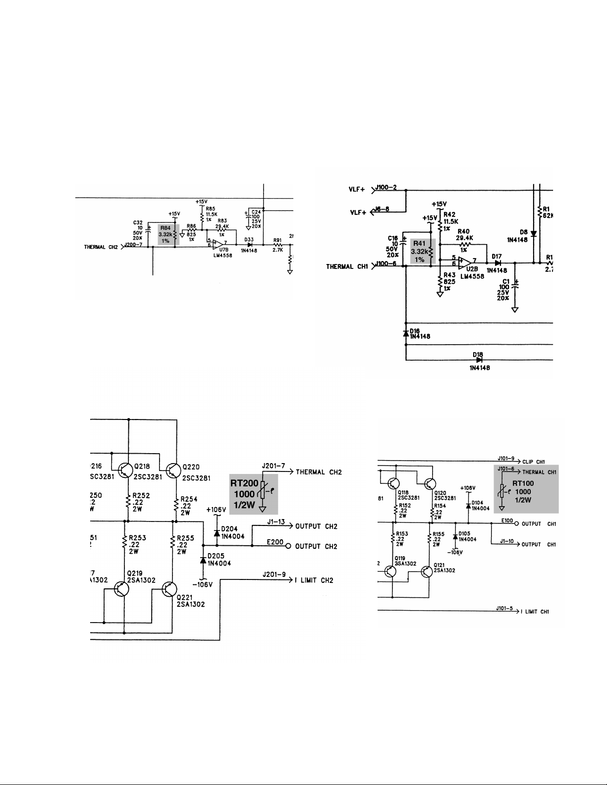
The thermistors RT100 and RT200 used in the 1800V protection circuit have changed. The resistors R41 and R84 had to be changed to match the new thermistors. The thermistors RT100 and
RT200 are located on the amplifier PCB. The resistors R41 and R84 are located on the I/O PCB.
Refer to the 1800V service manual, part number 181812, for disassembly procedures, schematics,
and PCB layouts. Refer to the figures on the back of this page for the location of the thermistors
and resistors. The tables below list the proper resistor and thermistor combination. It is not necessary to change these components unless they have failed. Insert this supplement into the 1800V
service manual, part number 181812 REV 00.
®
®
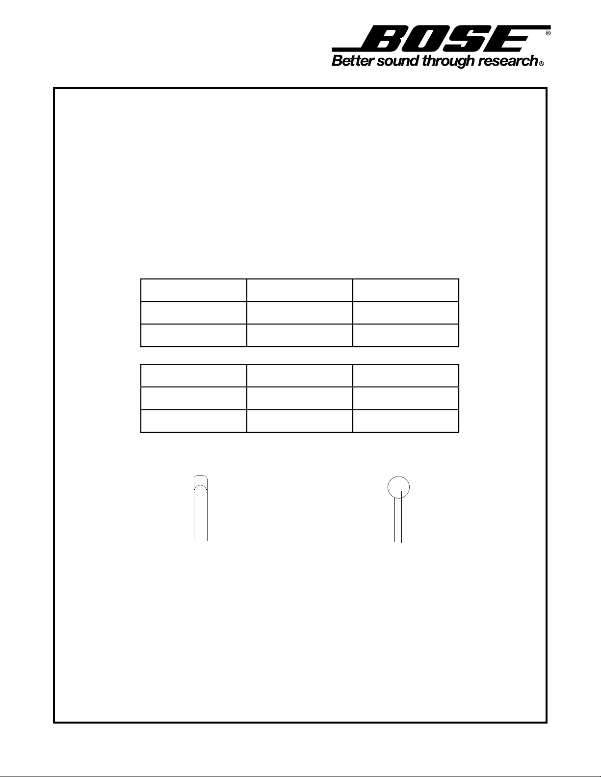
Reference
Designator
RT100, 200 Thermistor, NTC,
R41, 84 3.32k, MF, 1/4W,
Reference
Designator
RT100, 200 Thermistor, NTC,
R41, 84 2.21k, MF, 1/4W,
Description New Part Number
1/2W, 5%, 1k
1%
Description Old Part Number
1/2W, 5%, 1k
1%
195253
195252
182785
182908
New Thermistor Old Thermistor
©
1997 Bose Corporation
Rev00 08/97
Supplement
Part Number 181812-S4
Page 2
 Loading...