

Page 1
Model 151™ and 111™ ENVIRONMENTAL SPEAKER SYSTEM
Transducer: Cabinet:
1-4.5" (11.4 cm) full-range, Black or white high-impact molded
environmental driver polypropylene
Nominal Impedance: Speaker Dimensions:
4 Ohms 6.1"H x 9.1"W x 5.9" D
IEC Power Rating: Shipping Weight
Min: 10 Watts Per Channel 4.0 lbs. (1.8 kg) Per Speaker
Max: 40 Watts Per Channel
©
200 Bose Corporation
SPECIFICATIONS
(15.4 H x 23.0 W x 15.0 D cm)
Service Manual
Page 2

Test Procedures
NOTES: In each test procedure, it is necessary to remove the grille to access the driver.
Refer to the Grille Removal procedure.
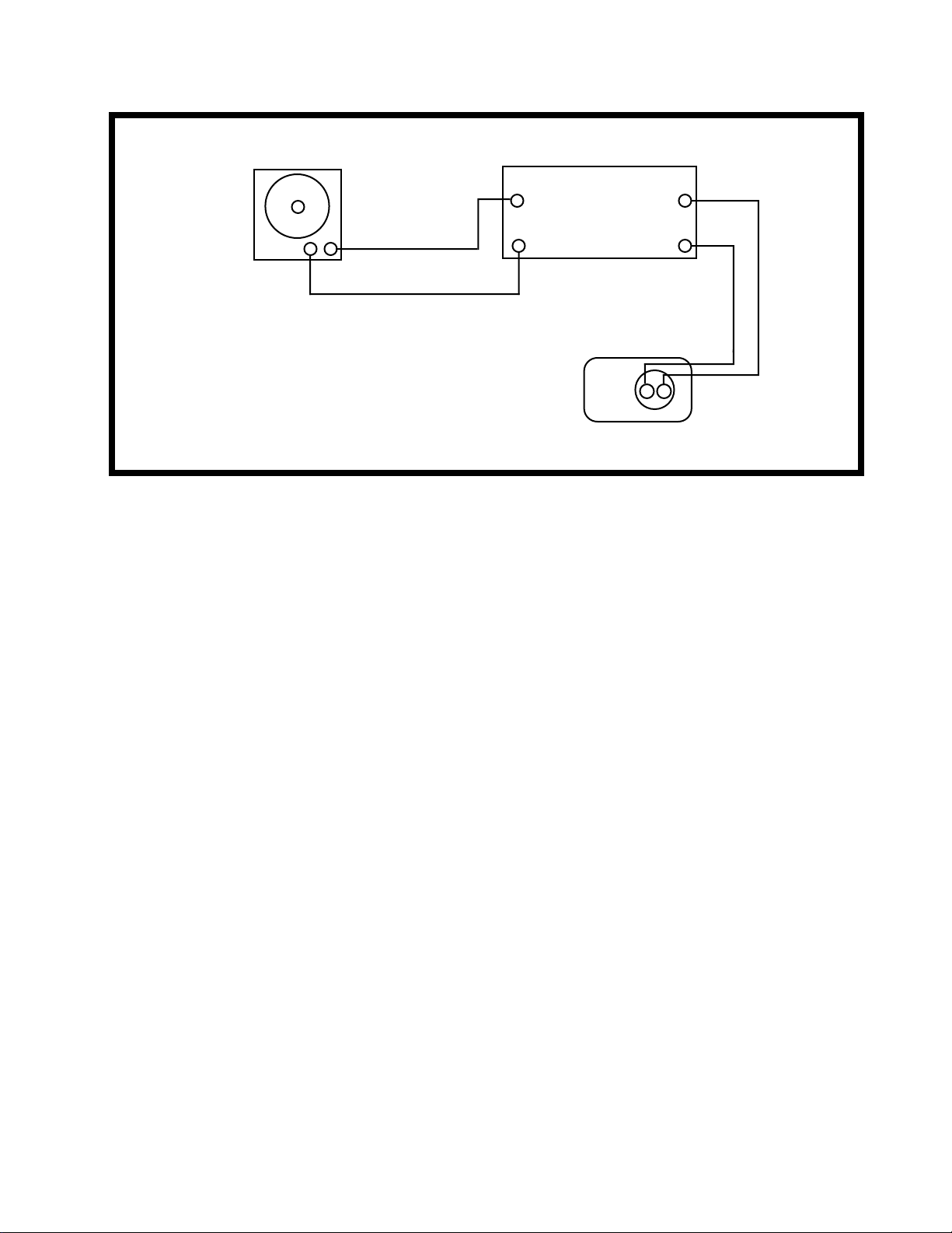
Polarities are not marked on the input terminals of the 151™ speaker. The red terminal is
the positive (+) terminal and the black terminal is the negative (-) terminal. See Figure 1.
1. Rub and Tick Test
A. Connect a sine wave oscillator to a power amplifier. Adjust the frequency of the oscillator
to 10 Hz and the amplifier output to 6 Vrms. Connect the amplifier output to the input
terminals of the 151 speaker (see Figure 1). No extraneous noises such as rubbing,
scraping or ticking should be heard.
NOTE: To distinguish between normal suspension noise and rubs or ticks, displace the
cone on the driver slightly with your fingers. If the noise can be made to go away or get
worse, it is a rub or a tick and the driver should be replaced. If the noise stays the same, it
is normal suspension noise and the driver is fine. Suspension noises will not be heard with
program material.
2. Sweep Test
A. Sweep the oscillator from 10 Hz to 3 kHz using the 6 Vrms signal. There should not be
any loud extraneous sounds. (Note: A "whooshing" noise from the port at approximately 80
Hz is acceptable). If there are any loud buzzes or distortion, replace the driver. (See
Disassembly/Assembly Procedures for instructions on replacing the driver).
NOTE: There should not be any buzzes or rattles from within the speaker cabinet. Redress
any wire or component that buzzes.
B. Reduce the amplifier output to 3 Vrms and continue sweeping from 3 kHz to 15 kHz. If
there is any buzzing or distorting,replace the driver (see Disassembly/Assembly
Procedures for instructions on replacing the driver).
1
Page 3
Audio Signal
Generator
Power Amplifier
Input Output
--
+
-
++
Speaker
-
+
Red (+)
Black (-)
Figure 1. Test Connections 151™ Speaker
3. Air Leak Test
A. Using the 6 Vrms signal,set the oscillator frequency to 10 Hz. Block the ports. For at
least 3 seconds, listen for air leaks around the driver and baffle. If there is a "whooshing"
noise around the driver, re-position the driver gasket behind the driver to make an airtight
seal. If there are similar noises around the baffle, make sure that it is securely fastened to
the speaker cabinet.
4. Phase Test
NOTE: Supply voltage should only be momentarily applied to the speaker input terminals to
avoid possible damage to the speaker.
A. Set a DC power supply to 10 volts. To ensure that the driver is connected in phase,
connect the positive lead of the supply to the positive (+) speaker input terminal and the
negative lead to the negative (-) input terminal. The driver should move outwards with the
application of the supply voltage.
2
Page 4

Disassembly/Assembly Procedures
NOTE: Refer to Figure 2 for an exploded view of the speaker assembly. Certain parts will
be referred to in these procedures. The item number which corresponds to the part will be
enclosed in parentheses-i.e.-grille (1).
1. Grille Removal
NOTE: The grille is made entirely of metal. Do not try to remove the grille by pulling on the
plastic (polypropylene) speaker enclosure.
A. Insert the tip of a scribe or nail through one of the perforations in the grille (1). Hint:
Insert at one of the corners. Carefully work the grille out of the retaining slot.
2. Grille Replacement
A. To install the grille (1), make sure that it is oriented as shown in Figure 2.
B. Align the grille to the speaker enclosure and push in lightly.
3. Driver Removal
A. Remove 3 screws (4) which secure the driver (3) to the speaker baffle (6).
B. Carefully lift the driver out of the enclosure and cut the wires as close to the driver
terminals as possible.
4. Driver Replacement
A. Strip the wires and connect to the replacement driver (3). Make sure that the red wire is
connected to the positive (+) terminal and the black wire is connected to the negative (-)
terminal of the driver. Make sure that the driver terminals are centered in the speaker
enclosure. The correct orientation is shown in Figure 2.
B. The gasket (5) must also be correctly positioned behind the driver to provide an airtight
seal. Secure the driver (3) to the baffle (6) with 3 screws (4). Repeat the driver test
procedures.
3
Page 5

5. Baffle Removal
A. Remove 6 screws (4) that hold the baffle (6) in place. (Removing the driver is not necessary).
Stick your fingers in the baffle ports and pull the baffle carefully away from the enclosure. It may
take quite a bit of force to accomplish this task.
6. Baffle Replacement
A. Align the port side of the baffle (6) to the side of the enclosure that has the input terminals (9).
The baffle will only fit one way. Secure the baffle to the enclosure with 6 screws (4). Repeat the air
leak test.
4
Page 6

Figure 2. Speaker Assembly Exploded View
5
Page 7

Figure 3. Packaging Exploded View
6
Page 8

151™ Speaker Assembly Parts List (Figure 2)
Item
Number
Description Part Number Qty.
Per
Speaker
Assy.
1 Grille -Metal, Black 179129-1 1 2
Grille -Metal, Arctic White 179129-2 1 2
2 Nameplate-Logo, Black 171292-1 1 2
Nameplate-Logo, White 171292-2 1 2
3 Driver 257948-001 1
4 Screw-
TAPP,8-11x3/4,PAN,XRC/SQ
173556-12 9
5 Gasket-Driver, 4.5" 128407 1
6 Baffle-Black 131741-01A 1
Baffle-White 131741-01B 1
7 Batting-Polyester 116082 1 1
8 Threaded Insert 123991 2
9 Connector-Terminal Strip 171295 1
See Note
10 Screw-
TAPP,6-13x.5,PAN,XREC/SQ
173555-08 2
NOTE
1. This part is not normally available from Customer Service. Approval from the Field Service Manager is
required before ordering.
2. The nameplate is not easy to replace. If you need to replace the grille, you must also order a new nameplate. Re-attach the nameplate to the grille with an appropriate adhesive (i.e.-superglue) or by using a
soldering iron. CAUTION: If you use a soldering iron, CAREFULLY melt the nameplate posts against the
grille. Do not melt down the posts too much or the nameplate will be ruined. Also, the nameplate should be
secured so that it does not vibrate.
7
Page 9

151™ Packaging Parts List (Figure 3)
Item
Number
Description Part Number Qty.
1 Owner's Manual 171297 1
2 Card-Warranty, Universal 149225 1
3 Polybag (Literature Kit) 103351 1
4 List-Warranty Service 122766 1
5 Envelope-Warranty Registration 123001 1
6 All Products Brochure 141478 1
7 Express Music Catalog 145891 1
8 Packing-Filler, Foam 124921 2
9 Polybag (Speaker) 123831 2
10 Carton 171298 N/A
See Note
Per
Carton
8
Page 10

SPECIFICATIONS AND FEATURES SUBJECT TO CHANGE WITHOUT NOTICE
Bose Corporation
The Mountain
Framingham, Massachusetts USA 01701
P/N 173445 6/93: REV.01
FOR TECHNICAL ASSISTANCE PARTS ORDERING, CALL 800-233-4008
 Loading...