

BOSE 102 Schematic
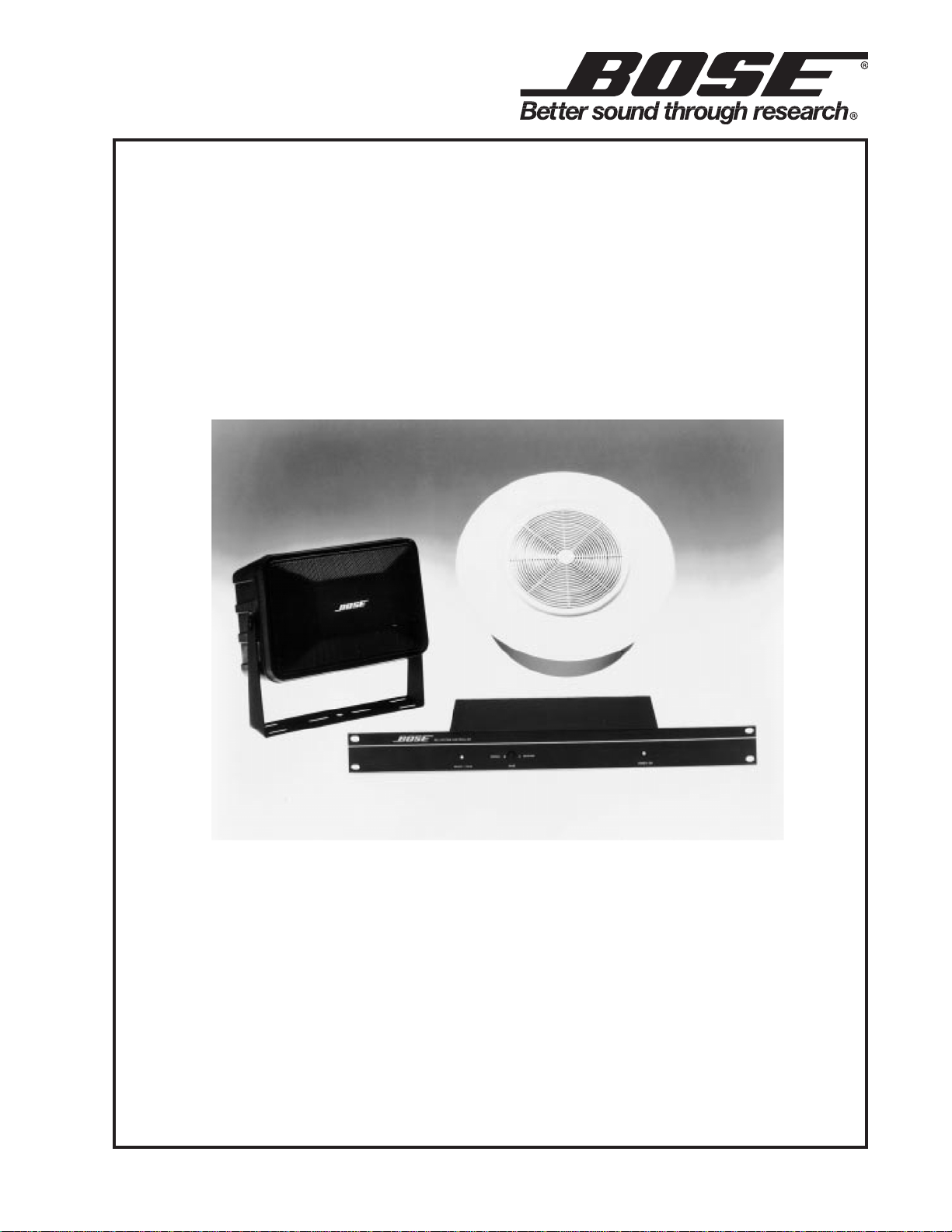
102 COMMERCIAL SOUND SYSTEM
©2009 Bose Corporation
Service Manual
Reference Number 130105-SM Rev . 04
Electronic Copy Only

CONTENTS
Electrostatic Discharge Sensitive (ESDS) Device Handling.........................................................3
Safety Information................................................................................................................................4
Specifications.......................................................................................................................................5
Disassembly/Assembly Procedures ............................................................................................. 6-9
102® Flush-Mount Loudspeaker........................................................................................................6
Figure 1. 102 Flush-Mount Grille Removal.............................................................................................6
Figure 2. 102 Flush-Mount Driver Replacement....................................................................................6
102 Surface-Mount Loudspeaker......................................................................................................7
Figure 3. 102 Surface-Mount Driver Removal/Replacement................................................................7
Figure 4. 102 Surface-Mount Baffle Assembly ......................................................................................8
102 System Controller Procedures................................................................................................8-9
Figure 5. 102 System Controller Exploded View ..................................................................................10
Figure 6. 102 System Controller Block Diagram ................................................................................11
T est Procedures ......................................................................................................................... 12-15
Figure 7. Test Connections for 102F or 102S Loudspeaker................................................................12
102 Loudspeaker T est Signals.........................................................................................................12
102 System Controller Test Procedures ...................................................................................... 13
102 System Controller Initial Switch Positions..............................................................................13
102 System Controller Frequency Response................................................................................14
102 System Controller T est Procedures...................................................................................14-15
102 System Controller V oice Channel Response..........................................................................15
102 Loudspeaker Driver Wiring ......................................................................................................16
Figure 8. 102 Loudspeaker Schematic Diagram (Passive Units).......................................................16
Figure 9. 102 Loudspeaker Schematic Diagram (Transformer Units)................................................16
Figure 10. Tap Selection Switch Wiring (Transformer Units)..............................................................16
T ap Selection Switch Wiring............................................................................................................16
102 Flush-Mount Loudspeaker Parts List (Per Figure 10) ......................................................... 17
102 Flush-Mount Loudspeaker Installation Hardware ................................................................ 17
102 Loudspeaker Exploded Views ................................................................................................ 18
Figure 1 1a. 102 Flush-Mount Non-RoHS Loudspeaker Exploded View ............................................ ..18
Figure 1 1b. 102 Flush-Mount RoHS Loudspeaker Exploded View ......................................................18
102 Surface-Mount Loudspeaker Parts List (Per Figures 11 & 12) ........................................... 19
102 Surface-Mount Loudspeaker Installation Hardware ............................................................ 19
Figure 12. 102 Surface-Mount Loudspeaker Exploded View ...............................................................20
Figure 13. 102 Surface-Mount Loudspeaker ..................................................................................... 21
102 System Controller Parts Lists ............................................................................................ 22-25
102 System Controller Packing List .............................................................................................. 25
102 Loudspeaker Packing Diagrams ........................................................................................ 26-27
Figure 14. 102 Flush-Mount Loudspeaker Packing Diagram..............................................................26
Figure 15. 102 Surface-Mount Loudspeaker Packing Diagram...........................................................27
Service Manual Revision History .....................................................................................................28
2

ELECTROSTATIC DISCHARGE SENSITIVE (ESDS)
DEVICE HANDLING
This unit contains ESDS devices. We recommend the following precautions when repairing,
replacing, or transporting ESDS devices:
• Perform work at an electrically grounded work station.
• Wear wrist straps that connect to the station or heel straps that connect to conductive floor mats.
• Avoid touching the leads or contacts of ESDS devices or PC boards even if properly grounded.
Handle boards by the edges only.
• Transport or store ESDS devices in ESD protective bags, bins, or totes. Do not insert
unprotected devices into materials such as plastic, polystyrene foam, clear plastic bags, bubble
wrap, or plastic trays.
CAUTION: THE 102® SYSTEM CONTROLLER CONTAINS
NO USER-SERVICEABLE PARTS. TO PREVENT
WARRANTY INFRACTIONS, REFER SERVICING TO
WARRANTY SERVICE STATIONS OR FACTORY SERVICE.
PROPRIETARY INFORMATION
THIS DOCUMENT CONTAINS PROPRIETARY INFORMATION OF
BOSE® CORPORATION WHICH IS BEING FURNISHED ONLY
FOR THE PURPOSE OF SERVICING THE IDENTIFIED BOSE
PRODUCT BY AN AUTHORIZED BOSE SERVICE CENTER OR
OWNER OF THE BOSE PRODUCT, AND SHALL NOT BE
REPRODUCED OR USED FOR ANY OTHER PURPOSE.
3

SAFETY INFORMATION
1. Parts that have special safety characteristics are identified by the ! symbol on
schematics or by special notes on the parts list. Use only replacement parts that
have critical characteristics recommended by the manufacturer.
2. Make leakage current or resistance measurements to determine that exposed
parts are acceptably insulated from the supply circuit before returning the unit
to the customer. Use the following checks to perform these measurements:
A. Leakage Current Hot Check
(1) With the unit completely reassembled, plug the AC line cord directly
into a 120V AC outlet. Do not use an isolation transformer during
this test. Use a leakage current tester or a metering system that
complies with American National Standards Institute (ANSI) C101.1
"Leakage Current for Appliances" and Underwriters Laboratories (UL) 1492 (71).
(2) With the unit AC switch first in the ON position and then in the OFF position,
measure from a known earth ground (metal water pipe, conduit, etc.) to all
exposed metal parts of the unit (antennas, handle bracket, metal cabinet,
screwheads, metallic overlays, control shafts, etc.), especially any
exposed metal parts that offer an electrical return path to the chassis.
(3) Any current measured must not exceed 0.5 milliamp.
(4) Reverse the unit power cord plug in the outlet and repeat test.
ANY MEASUREMENTS NOT WITHIN THE LIMITS SPECIFIED HEREIN
INDICATE A POTENTIAL SHOCK HAZARD THAT MUST BE ELIMINATED
BEFORE RETURNING THE UNIT TO THE CUSTOMER.
B. Insulation Resistance Test Cold Check
(1) Unplug the power supply and connect a jumper wire between the two
prongs of the plug.
(2) Turn on the power switch of the unit.
(3) Measure the resistance with an ohmmeter between the jumpered AC plug
and each exposed metallic cabinet part on the unit. When the exposed
metallic part has a return path to the chassis, the reading should be
between 1 and 5.2 megohms. When there is no return path to the chassis,
the reading must be "infinite". If it is not within the limits specified, there is
the possibility of a shock hazard, and the unit must be repaired and
rechecked before it is returned to the customer.
4

SPECIFICATIONS
102® System Controller:
Input Level: Music - 100mV or 1V selectable
Voice - Mic or line, selectable, variable
(AGC calibration)
Output Level: 1V nominal
Input Impedance: Music - 2k ohms, balanced, differential
Voice - 600 ohms, balanced, differential
Bass Cut Switch: 6 dB
Distortion: Less than 0.1% THD
CMRR: Greater than 40 dB, all inputs
AGC: Attack level - variable
Attack time - < 5 ms
Release time - 200 ms
Mute: Mute level - -30 dB ( with defeat switch on ch. B)
Attack time - < 5 ms
Release time - 2 seconds
Accessories: 4 rack-mount screws, supplied
Dimensions: 1 3/4" H x 18 31/32" W x 4 1/4" D
(44 mm x 482 mm x 107 mm)
102 Flush-Mount and 102 Surface-Mount Loudspeakers:
Frequency Response: 80 Hz - 18 kHz, ± 3 dB
Distortion: <1% @ 10% rated power input
Driver: Single, 4 1/2" Helical Voice Coil
Enclosure: Dual port, bass reflex type
Volume: 200 cubic inches
Port Resonance: 80Hz
Sensitivity: 95 dB SPL, 1W, 1m @ 1 kHz
Weight: 5 lbs. (2.3 kg)
Temperature: Minimum - 0° C
Maximum - 60° C
Humidity: Minimum - 0 %
Maximum - 98 %
5
DISASSEMBLY/ASSEMBLY PROCEDURES
102® Flush-Mount Loudspeaker
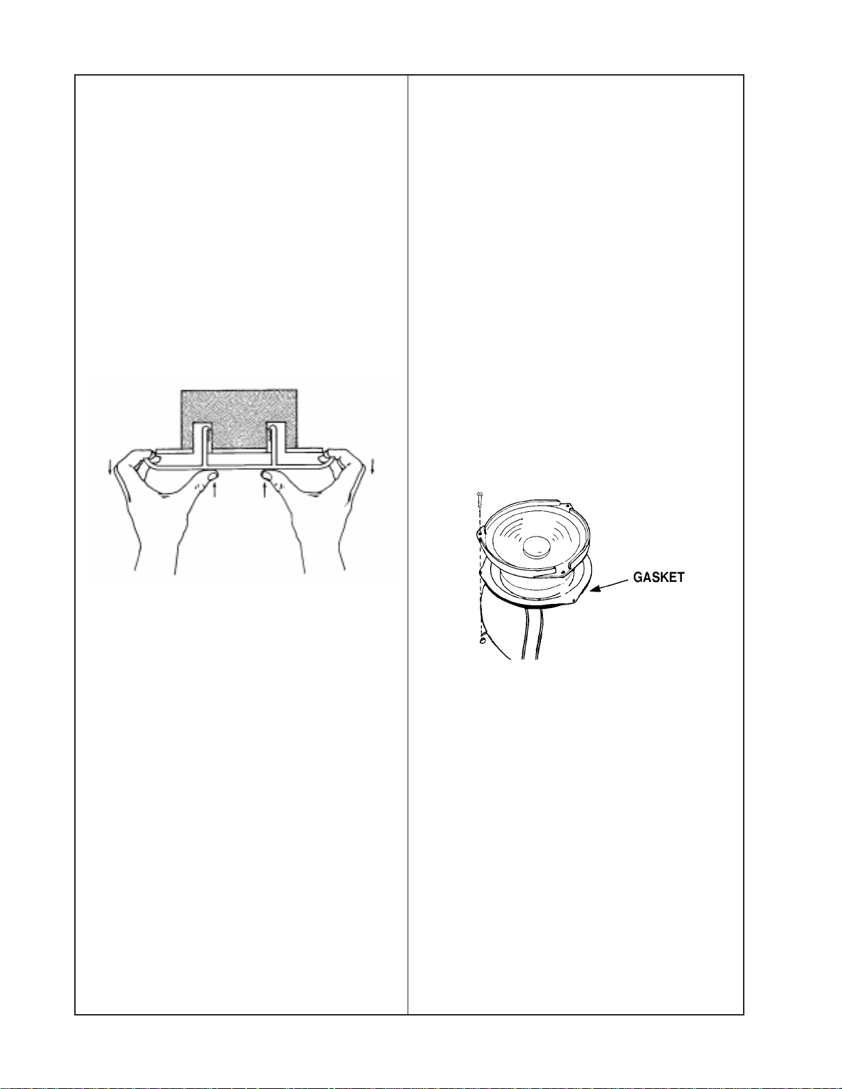
1. Grille Removal
1.1 The optional Bose® grille is held in
place via a tooth/groove-type design.
To remove the grille, grasp the edges of the
grille with your fingers and place your
thumbs toward the center of the grille.
1.2 As you press inward with your thumbs,
pull outward with your fingers. This will
release the teeth from the grooves, allowing the grille to be removed from the loudspeaker enclosure. (See Figure 1)
3.2 Carefully lift the driver out of the enclosure and cut the wires as close to the driver
terminals as possible.
4. Driver Replacement
4.1 Strip the wires and connect them to
the replacement driver. Make sure that
the red wire is connected to the
positive (+) terminal and the black wire
is connected to the negative (-) terminal
of the driver.
4.2 Align the driver and gasket to the
enclosure. Make certain the gasket is
correctly positioned to provide an airtight
seal.
4.3 Secure the driver to the enclosure with
the three screws. Do not overtighten.
(See Figure 2)
Figure 1. 102 Flush-Mount Grille Removal
2. Grille Replacement
2.1 Align the legs on the grille with the
openings in the speaker enclosure.
2.2 Press the grille upward so that the
teeth on the grille legs engage the teeth in
the speaker enclosure.
2.3 Push the grille upward until the
grille is flush with the mounting surface.
3. Driver Removal
3.1 Using a flat-blade screwdriver or a 1/4"
socket, remove the three screws holding
the driver in place.
Figure 2. 102 Flush-Mount Driver
Replacement
6
DISASSEMBLY/ASSEMBLY PROCEDURES
Note: The following procedures are for the
transformered units only. The passive
versions do not have a tap selection switch,
transformer, or capacitor within the enclosure.
5. Wiring-Well Cover:
(Transformer and Capacitor Access)
5.1 To remove the wiring-well cover
located in the back of the enclosure, use a
flat-blade screwdriver or a 1/4" socket to
loosen the two screws that hold the metal
cover in place.
5.2 Swing the cover free to gain access to
the transformer and capacitor.
6. Front plate removal
(Access to tap selection switch)
6.1 Using a flat-blade screwdriver or a 1/4"
socket, remove the two screws that hold
the plastic front plate in position.
6.2 Lift the plate out to gain access to the
tap selection switch and wiring.
102® Surface-Mount Loudspeaker
1. Grille Removal
2.2 Fit the grille to two adjacent corners of
the enclosure.
2.3 Gently apply pressure to the two
remaining corners to fit the grille into the
enclosure.
3. Driver Removal
3.1 Using a cross-head screwdriver,
remove the three screws that hold the
driver in place.
3.2 Carefully lift the driver out of the
enclosure and cut the wires as close
to the driver terminals as possible.
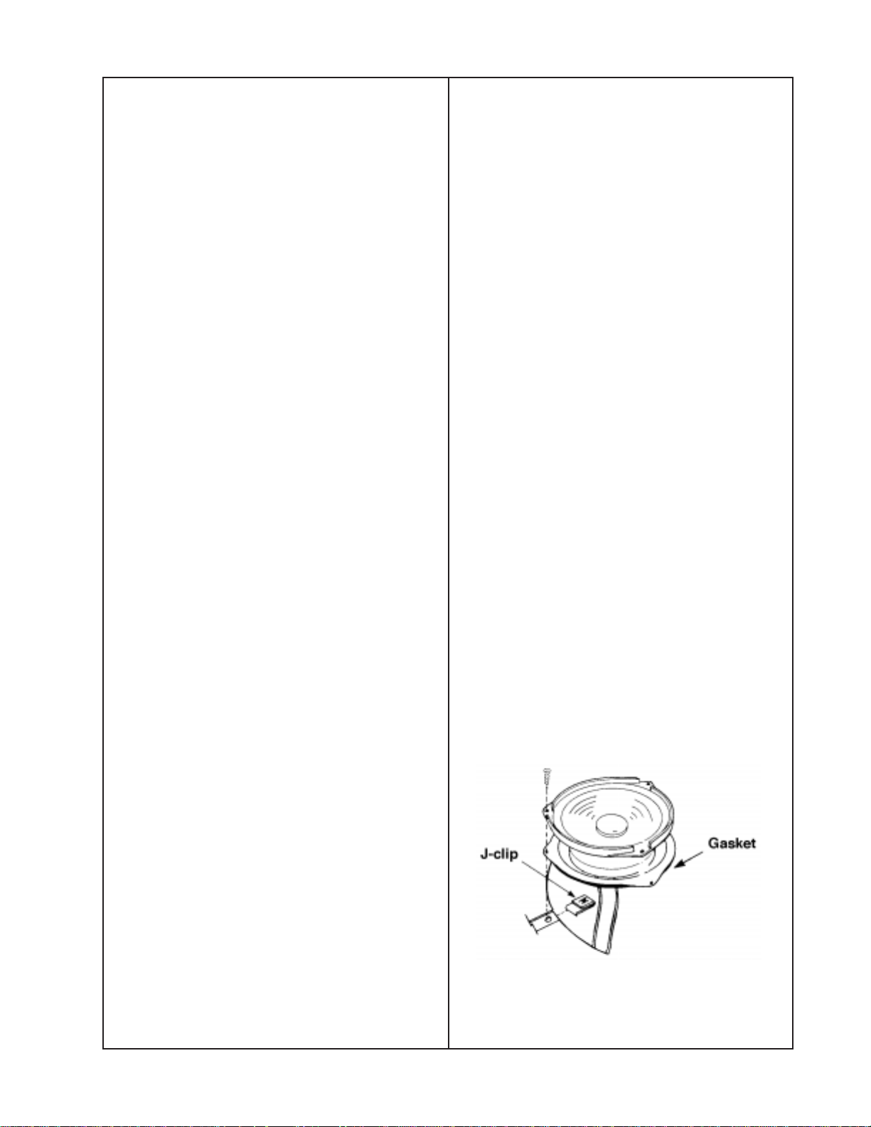
4. Driver Replacement
4.1 Strip the wires and connect them
to the replacement driver.
Note: Make certain that the red wire is
connected to the positive (+) terminal and
the black wire is connected to the
negative (-) terminal of the driver.
4.2 Align the driver and gasket to the
J-clips. Make sure the gasket is correctly
positioned behind the driver to provide an
airtight seal.
1.1 To remove the grille, take a small
flat-blade screwdriver or scribe and grasp
the edge of the grille at one of the corners.
1.2 Gently work the grille out of the retaining slot.
Note: There is no grille frame exposed.
You must grasp the grille on the metal
portion of the grille and not on the polystyrene, which is part of the speaker
enclosure.
2. Grille Replacement
2.1 To install the grille, first be sure that
the Bose® logo is facing the same way as
the print on the back of the enclosure.
4.3 Secure the driver to the J-clips with
the three screws. Do not overtighten.
(See Figure 3)
Figure 3. 102 Surface-Mount Driver
Replacement
7
DISASSEMBLY/ASSEMBLY PROCEDURES
Note: The following procedures are for the
transformered units only. The passive
versions do not have a tap selection switch
or transformer within the enclosure.
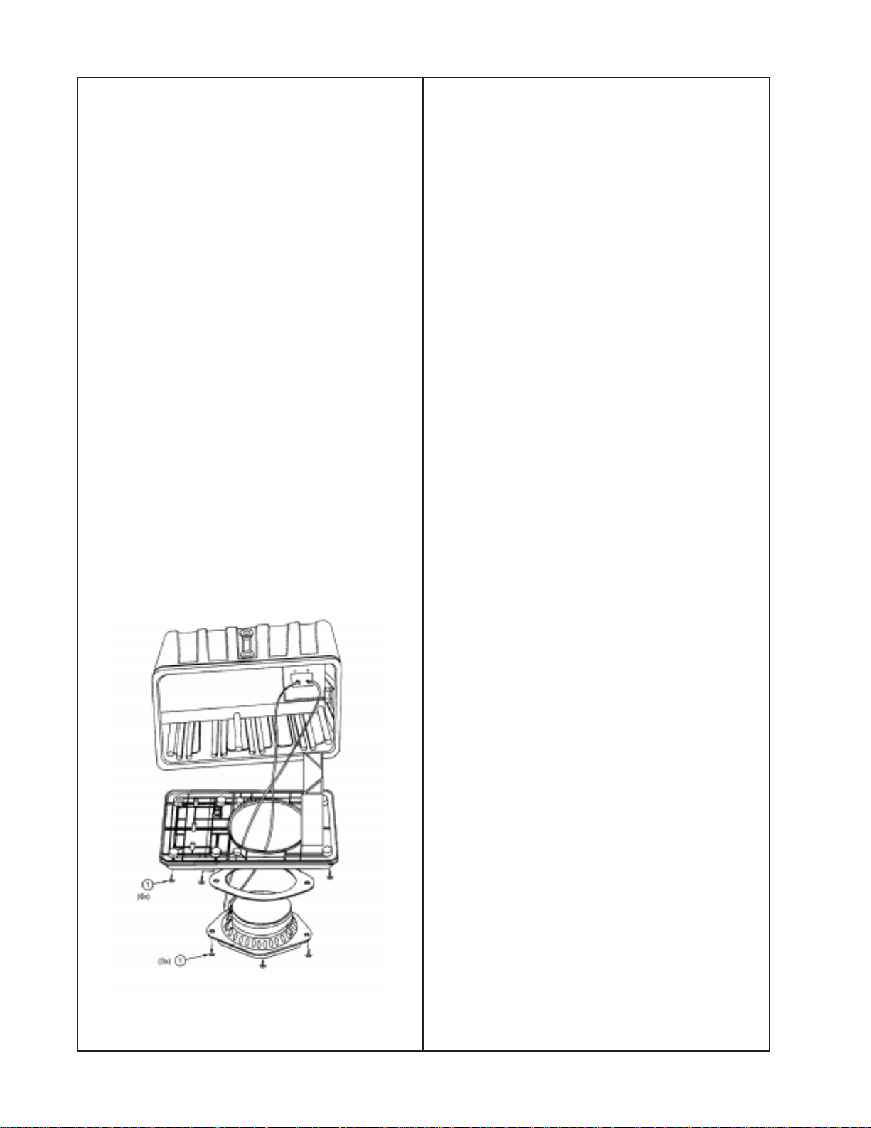
5. Baffle Removal
102
System Controller Procedures
1. Top Cover Removal
Note: Refer to Figure 5, 102 System
Controller Exploded View.
5.1 Remove the six screws (1) that hold
the baffle in place. Do not remove the
three screws holding the driver in place.
(See Figure 4)
5.2 Pry the baffle away from the enclosure
body. This can be accomplished by inserting the hook portion of a scribe or your
fingers into the ports and using this as a
grasping area to pry the two sections apart.
This will expose the tap selection switch
and transformer.
6. Baffle Replacement
6.1 Align the port side of the baffle to the
side of the enclosure that has the input
terminals.
6.2 Secure the baffle with the six screws.
1.1 Using a cross-tip screwdriver, remove
the six screws (1) securing the top cover,
(2) of the unit. There is one located on top,
two on the sides, and three on the back
panel.
1.2 Slide the top cover toward the rear of
the unit until it clears the ribs on the front
panel (3), then lift it straight off.
2. Top Cover Replacement
2.1 Align the top cover (2) with the rear
panel, and slide it down and forward until it
is in place against the front panel (3).
2.2 Secure the top cover using the six
screws (1) removed in procedure 1.1.
3. Front Panel Removal
3.1 Remove the top cover (2) using
procedures 1.1 and 1.2.
Figure 4. 102® Surface-Mount Baffle Assembly
3.2 Turn the unit over, and remove the
three screws (4) that secure the front panel
(3) to the chassis (5).
3.3 Slide the front panel off of the chassis.
4. Front Panel Replacement
4.1 Slide the front panel (3) onto the
chassis (5), aligning the holes for the LEDs
and push-switch.
4.2 Secure the front panel to the chassis
using the three screws (4) removed in
procedure 3.2.
4.3 Replace the top cover (2) using
procedures 2.1 and 2.2.
8

DISASSEMBLY/ASSEMBLY PROCEDURES
5. Main Circuit Board Removal
5.1 Remove the top cover (2) using
procedures 1.1 and 1.2.
5.2 Unplug the four cables from the con-
nectors on the circuit board (6) at JE02,
JE01, JE51, and JG01.
Note: You must first lift the tab on the
connector to release the wire.
5.3 Remove the front panel (3) using
procedures 3.1 through 3.3.
5.4 Remove the five screws (7) that
secure the circuit board to the chassis (5).
5.5 Slide the circuit board forward out
of the chassis.
6. Main Circuit Board Replacement
6.1 Align the circuit board (6) with the tabs
located on the chassis (5).
6.2 Replace the front panel (3) using
procedures 4.1 through 4.3.
6.3 Plug the four cables removed in
procedure 5.2 back into their respective
connectors.
6.4 Replace the top cover (2) using
procedures 2.1 and 2.2.
9
 Loading...