

Page 1
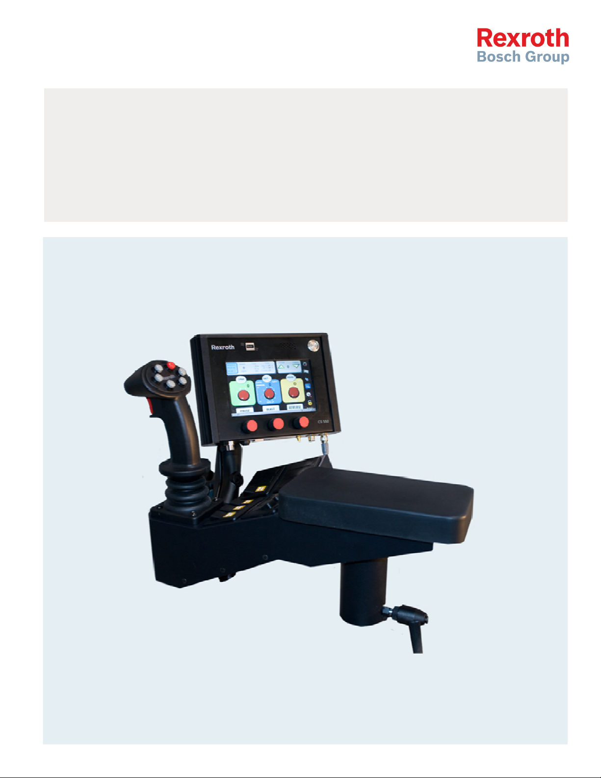
CS
550/150
RC
Spreader And Joystick Controller Calibration Manual
Page 2

2/32
Table o
Table of Content
Table oTable o
1111 Programming Mode
2222 Program
3333 Changing Fields
4444 Initial Set
5555 Ground Speed Calibration
6666 Valve Nulling
6.1 Auto Nulling 8
6.2 Manual Nulling 8
7777 Gate Calibration
8888 Material Calibration
9999 Material Catch Test
10
10 Load Parameters
1010
11
11 Advanced Features
1111
11112222 WiFi
11113333 Optional Modes and Operation
13.1 Pattern/Chute Mode 17
13.2 Air Gate Mode 17
13.3 Liquid+ Mode 18
13.4 Cross Conveyor 19
13.5 Spinner Reverse Mode 21
13.6 Solid reduction for Prewet 21
13.7 Dedicated 3 Boom Anti-ice 22
11114444 Optional Modes
14.1 Liquid – 1 Boom Anti-icing 23
13.2 Liquid – dedicated 3 Boom Anti-icing 24
11115555 Error Codes
16
16 Joystick
1616
16.2 Joystick Solenoid Nulling 30
16.2 Joystick Emergency (Panic Button) – If Equipped 30
11117777 Advanced Joystick S
17.1 Power Float 31
17.2 Function Labels 31
11118888 Warning
f Contentssss
f Contentf Content
Programming Mode 3333
Programming ModeProgramming Mode
Program Screen Layout
Program Program
Changing Fields –––– Data Entry
Changing Fields Changing Fields
Initial Set----up
Initial SetInitial Set
Ground Speed Calibration 7777
Ground Speed CalibrationGround Speed Calibration
Valve Nulling –––– Conveyor/Spinner/Prewet/Norm
Valve NullingValve Nulling
Gate Calibration 9999
Gate CalibrationGate Calibration
Material Calibration 10
Material CalibrationMaterial Calibration
Material Catch Test 11112222
Material Catch TestMaterial Catch Test
Load Parameters 11113333
Load ParametersLoad Parameters
Advanced Features 11114444
Advanced FeaturesAdvanced Features
WiFi and GPS tracking
WiFi WiFi
Optional Modes and Operation 11117777
Optional Modes and OperationOptional Modes and Operation
Optional Modes and Operation
Optional Modes Optional Modes
Error Codes 22225555
Error CodesError Codes
Joystick Calibration
Joystick Joystick
Advanced Joystick Set
Advanced Joystick SAdvanced Joystick S
Warning 31
WarningWarning
Screen Layout 4444
Screen LayoutScreen Layout
Data Entry 5555
Data EntryData Entry
up 6666
upup
Conveyor/Spinner/Prewet/Norm 8888
Conveyor/Spinner/Prewet/NormConveyor/Spinner/Prewet/Norm
10
1010
and GPS tracking 11115555
and GPS trackingand GPS tracking
and Operation ---- 550 Lite
and Operation and Operation
Calibration 30
CalibrationCalibration
et----up
up 31
etet
upup
550 Lite 23
550 Lite550 Lite
23
2323
30
3030
31
3131
31
3131
Bosch Rexroth Canada Corp. reserves the right to revise this information at any time and for
any reason and reserves the right to make changes at any time, without notice or obligation,
to any of the information contained in this piece of literature.
Please check for updates at: www.boschrexroth.ca/compu-spread
Bosch Rexroth Canada ı 07.10.2013 ı Revision 3.0
Page 3
3/32
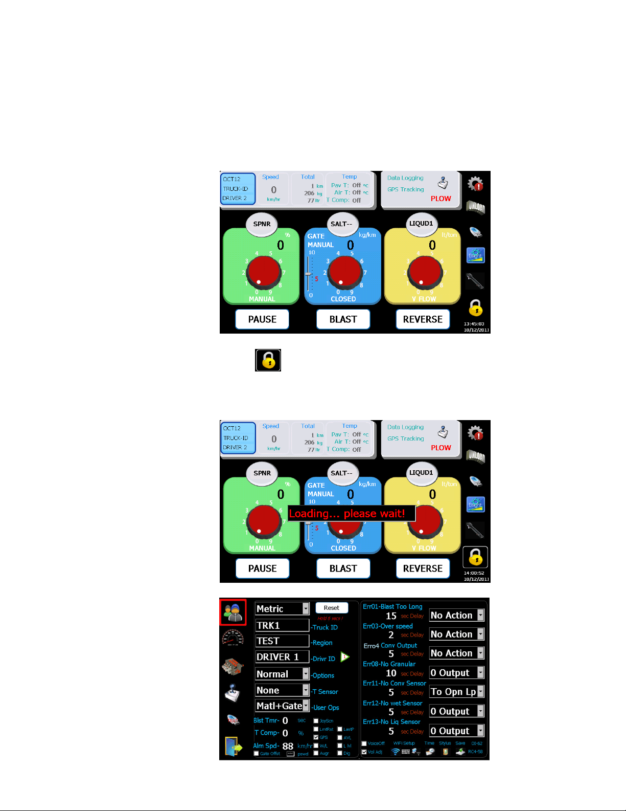
1 Programming Mode
All symbols on the right of the screen require a tap and hold for >1 second.
Press symbol to enter into programming mode.
Note: A valid PROGRAMMING USB key must be on the USB port. The
PROGRAMMING USB key is for programming and log data, and the LOG DATA USB
key will only retrieve data.
Bosch Rexroth Canada ı 07.10.2013 ı Revision 3.0
Page 4
4/32
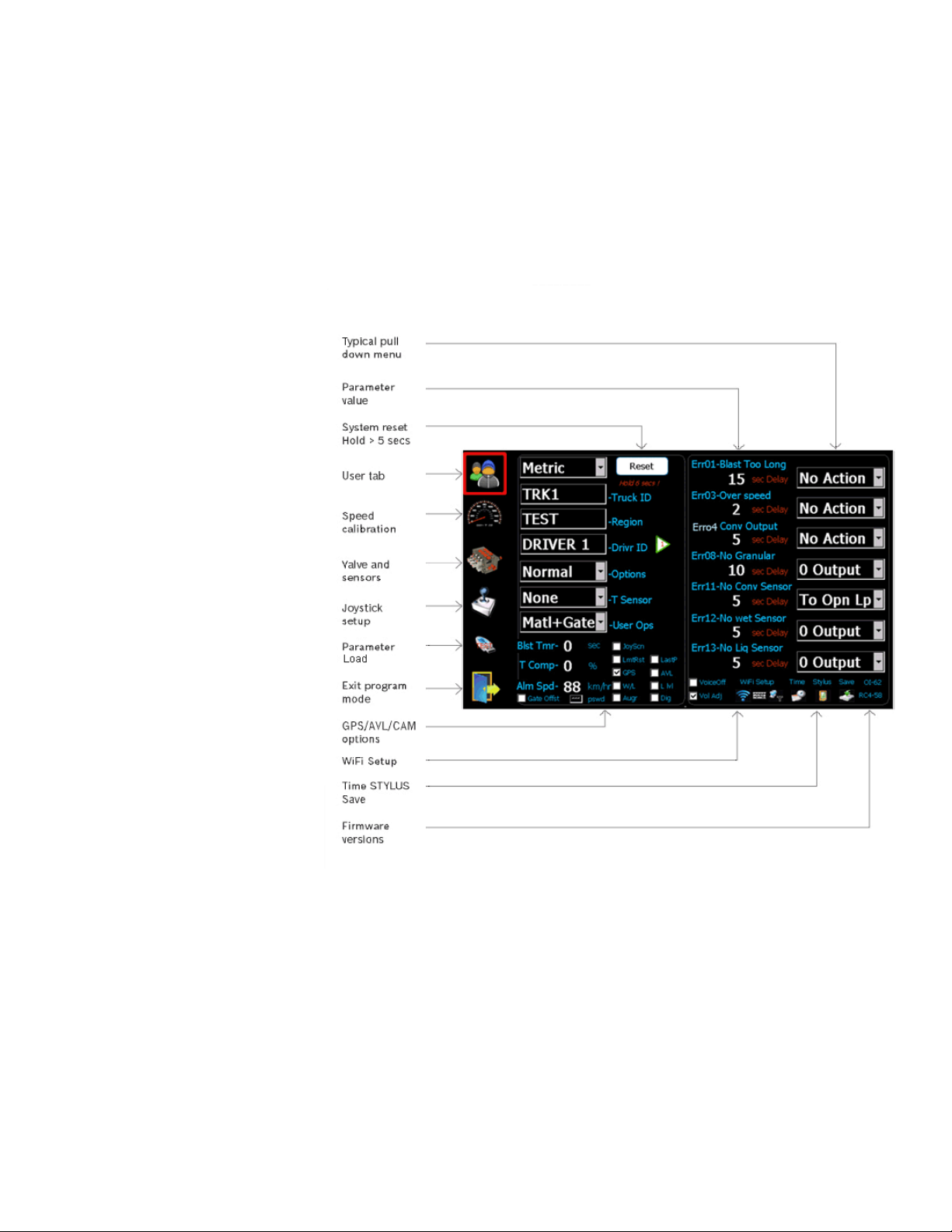
2 Program Screen Layout
Note: Due to the compact nature of these screens, the use of a selection tool like a
pen or stylus is recommended.
Bosch Rexroth Canada ı 07.10.2013 ı Revision 3.0
Page 5
5/32
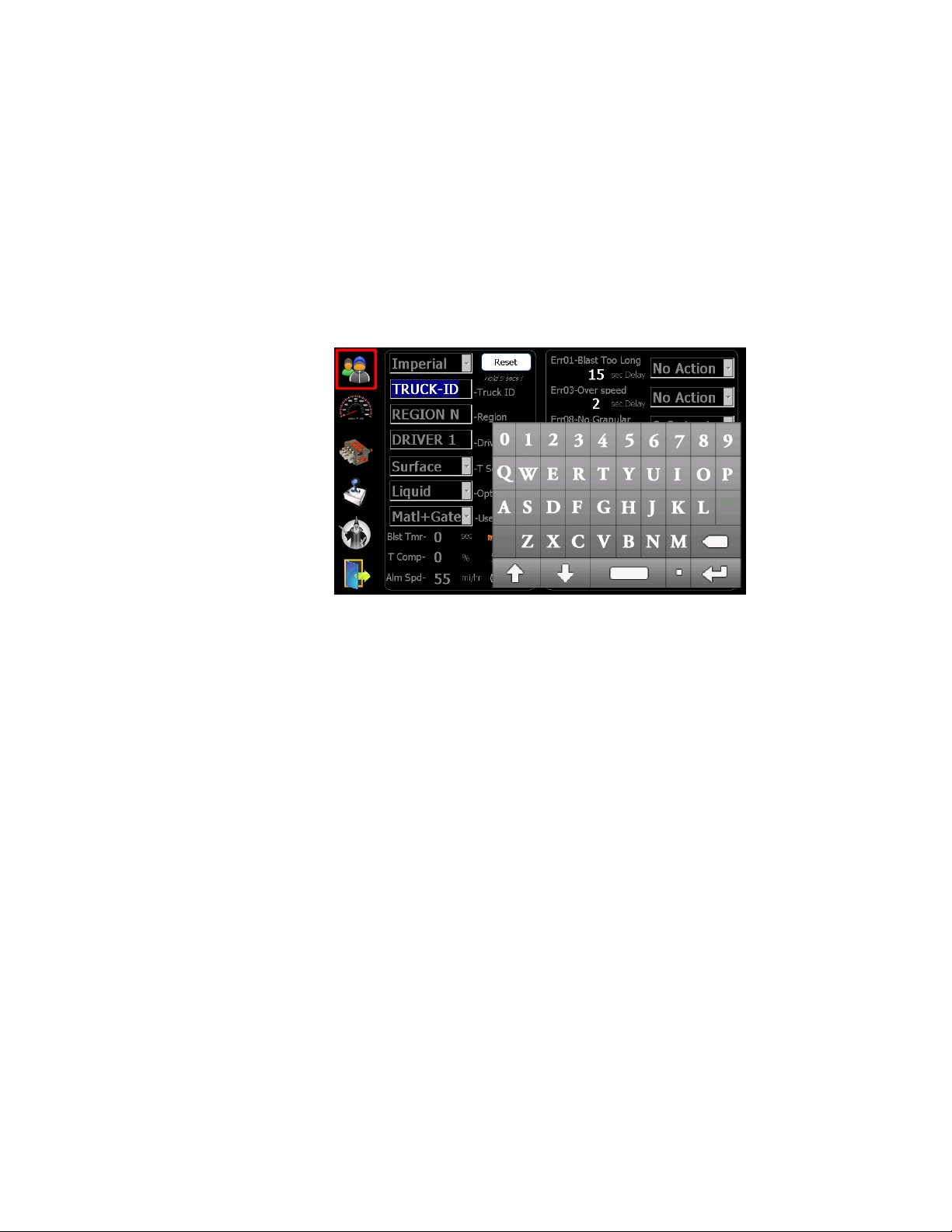
3 Changing Fields
Note: Due to the compact nature of these screens, the use of a selection tool like a
pen or stylus is recommended.
When selecting an item without a pull-down selection menu, a keypad is required.
This keypad is used to enter text or numeric values. The example shown is “TRUCKID”.
Bosch Rexroth Canada ı 07.10.2013 ı Revision 3.0
Page 6
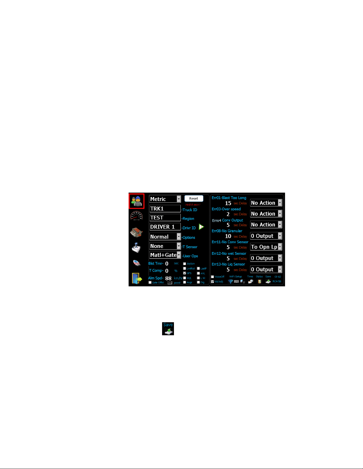
4 Initial Set-up
6/32
1. Set the units to imperial (LBS/Mile) or metric (Kg/Km).
2. Set the TRUCK ID.
3. Set the REGION NAME.
4. Set the DRIVER ID (optional), 4 driver IDs allowed.
5. Set the type of Temperature Sensor (optional).
6. Set the Options – see Advanced Features on page 13 (optional).
7. Set the items that the user has access to(optional).
8. Set Blast Timer, 0-timer disabled (optional).
9. Set Temp Compensation % based on 3 degree change (optional).
10. Set the vehicle speed alarm (optional).
11. Select AVL or GPS tracking (optional).
12. Set WIFI/TIME/STYLUS (if required).
The default error configuration values will work well for most applications, no
changes required.
Note: Save only applies to changes to Date/Time+WiFi+Stylus.
Bosch Rexroth Canada ı 07.10.2013 ı Revision 3.0
Page 7

7/32
5 Ground Speed Calibration
1. Select symbol to enter into the ground speed calibration screen.
2. Choose which calibration option best suits your situation.
3. Follow the instructions on the screen.
4. Press Start when the vehicle speed is steady.
5. Once calibration is complete, verify the speed by driving the vehicle through its
speed range and verify if the controller matches the speedometer.
Bosch Rexroth Canada ı 07.10.2013 ı Revision 3.0
Page 8
8/32
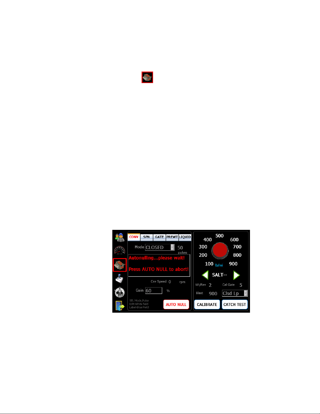
6 Valve Nulling – Conv/Spn/Prewet/Norm
1. Select symbol to enter into the calibration screen.
2. Select the appropriate mode:
Spinner
Spinner – Manual (default)
SpinnerSpinner
Conve
Conveyor/Auger
yor/Auger – Manual, Open, Closed (default)
ConveConve
yor/Augeryor/Auger
Prewet
Prewet – Fixed, V-Flow (default), Manual, Manual-SPD, Return Oil
PrewetPrewet
Gate
Gate – Manual (default), Read Back, Auto
Gate Gate
Norm
Norm (Anti-icing) – Off (default), 1 Boom, 3 Boom, Manual
Norm Norm
3. Set correct conveyor sensor pulses/rev if Closed loop is selected.
4. Ensure the hopper is empty, and the truck is safe to operate.
5. Start the engine to achieve adequate oil flow.
If the Closed loop mode is selected for Conveyor
Prewet
Prewet, and
, and 1Boom or 3 Boom is selected for Nor
PrewetPrewet
, and , and
recommended to run Auto Null
Manual Nulling instructions.
Auto Null. For manual mode please skip 6.1
Auto NullAuto Null
6.1 Auto Nulling
1. Press “Auto Null” to start. This procedure automatically run the system, and set
both “Min” and “Max” for the motor selected, Auger, Prewet, Anti-icing, etc...).
2. Note: This feature can only be used with motors with speed or flow feedback
(i.e. Conveyor/ Auger, Prewet, Anti-icing, etc.).
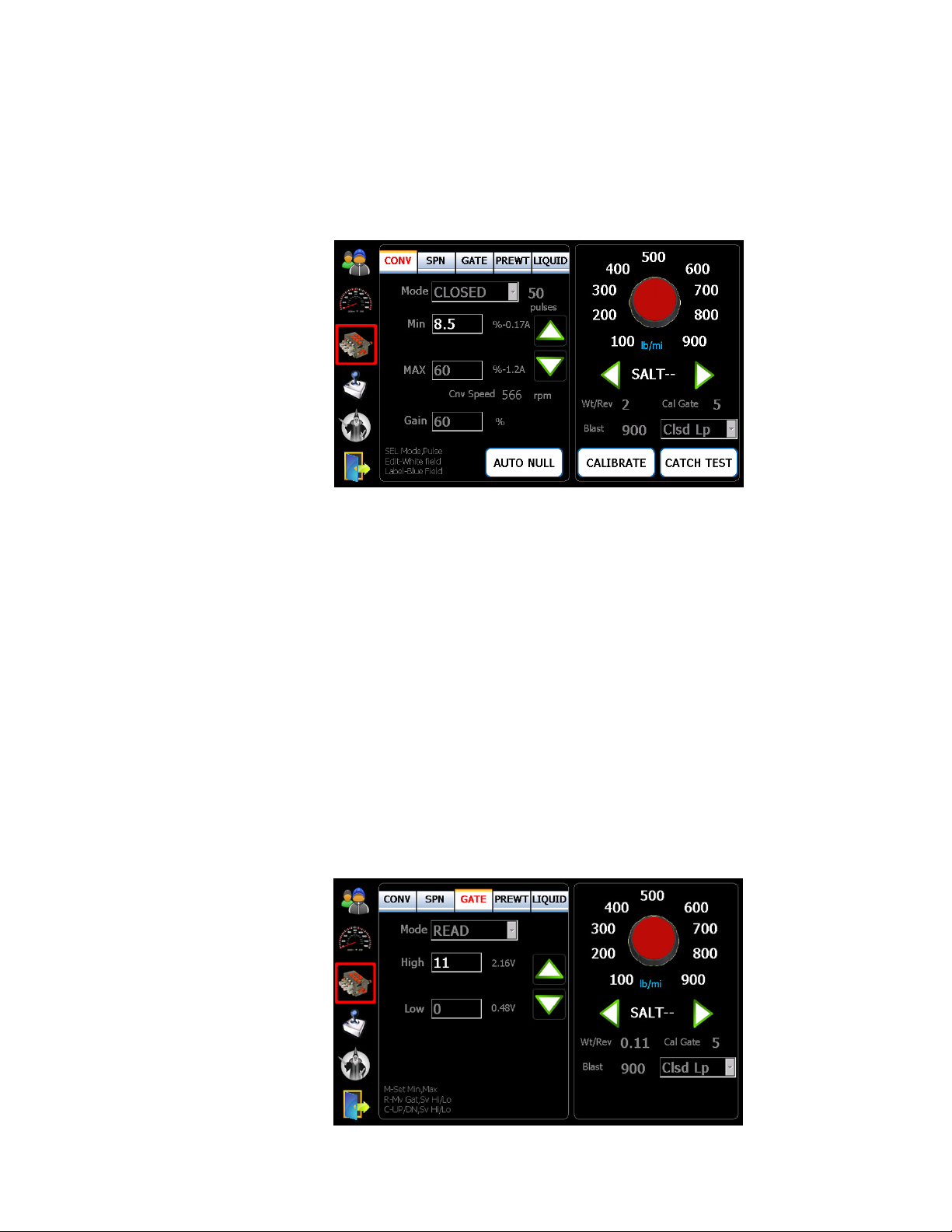
6.2 Manual Nulling
1. Press “Min” value field to enter into edit mode.
2. Use up and down arrows to adjust speed so that the motor just begins to turn
3. Press the “Min” value field again to end the edit mode and accept the value
4. Do the same for “Max” except adjust the motor to a safe maximum speed or
until the RRM readout stops to increase.
Conveyor, V-Flow or Return Oil mode for
ConveyorConveyor
Normmmm (Anti-icing) it is strongly
NorNor
6.1 and follow 6.2
6.16.1
6.2
6.26.2
Bosch Rexroth Canada ı 07.10.2013 ı Revision 3.0
Page 9
9/32
5. Forward Gain and Blast settings can also be adjusted
6. Repeat this procedure for all the vehicle motors (i.e. Conveyor/Auger, Spinner,
Prewet, Anti-icing, etc.).
7 Gate Calibration
1. Select the Gate tab.
2. Select the appropriate mode of gate operation :
Manual
Manual - Enter max height, and no further calibration required.
ManualManual
Read back
Read back - Press High
Read backRead back
- Move the gate to its max opening
- Press High
- Repeat the same procedure for Low
Note: A Gate Position Sensor required for Read back.
Auto
Auto - Press High
AutoAuto
- Press Up/Down buttons to move the gate to max opening
- Press High
- Repeat the same procedure for Low
Note: A gate cylinder with a position Sensor required.
High value field to enter into edit mode
HighHigh
High value field to end mode and save the value
HighHigh
Low value
LowLow
High value field to enter into edit mode
HighHigh
High value field to end mode and save the value
HighHigh
Low value
LowLow
Bosch Rexroth Canada ı 07.10.2013 ı Revision 3.0
Page 10
8 Material Calibration
Solid Material Calibration
Solid Material Calibration
Solid Material CalibrationSolid Material Calibration
10/32
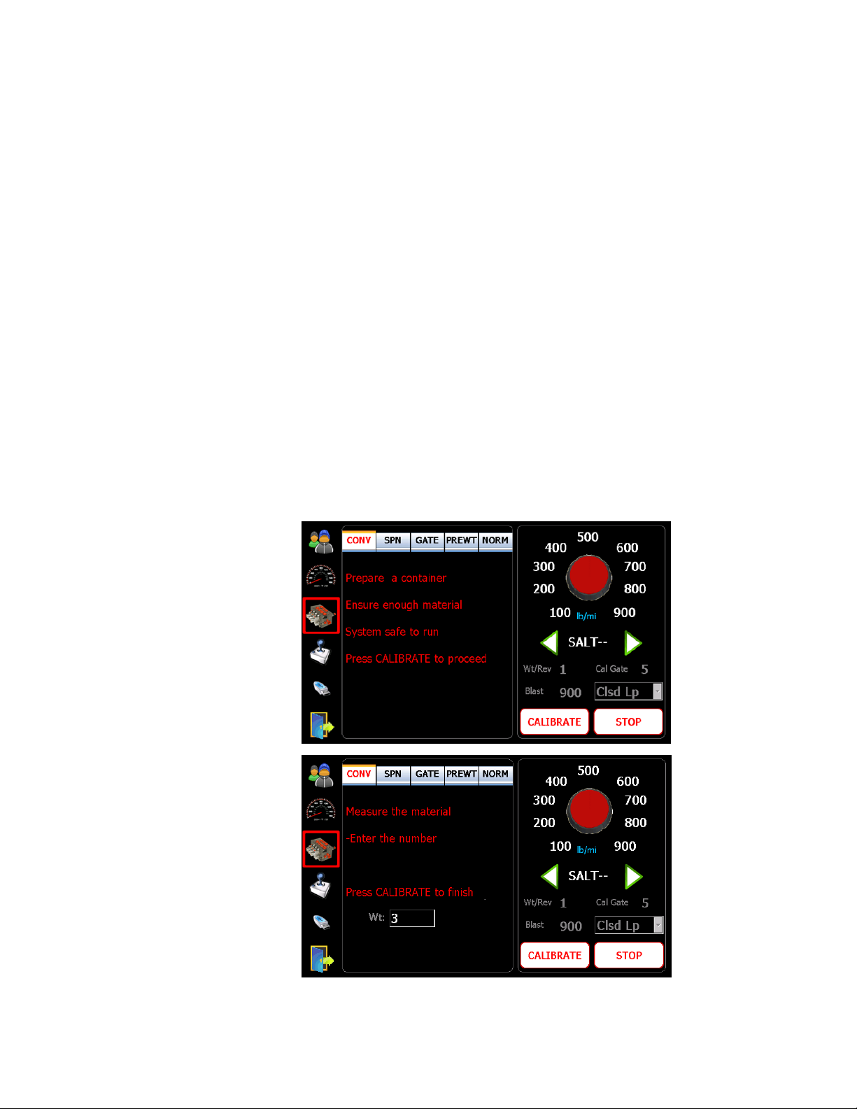
1. Tap on the “valve” symbol and CONV
2. Place an adequate catch container under the spreader discharge chute.
3. Make sure that sufficient material in the hopper and the system is safe to run.
4. Set gate position:
Manual
Manual - Change CAL Gate to match actual gate position
ManualManual
Readback
Readback - Adjust actual gate position on the truck
ReadbackReadback
Auto
Auto - Set to a desired gate position for calibration
AutoAuto
5. Press “CALIBRATION” button to proceed.
6. Turn CONV Knob and/or SPN Knob to run.
7. Stop when desired amount is reached.
8. Weigh the material and enter the value.
9. Press “CALIBRATION” Button to complete.
Note: Press “STOP” button to stop the process anytime during calibration.
CONV tab to enter into solid calibration.
CONVCONV
Bosch Rexroth Canada ı 07.10.2013 ı Revision 3.0
Page 11
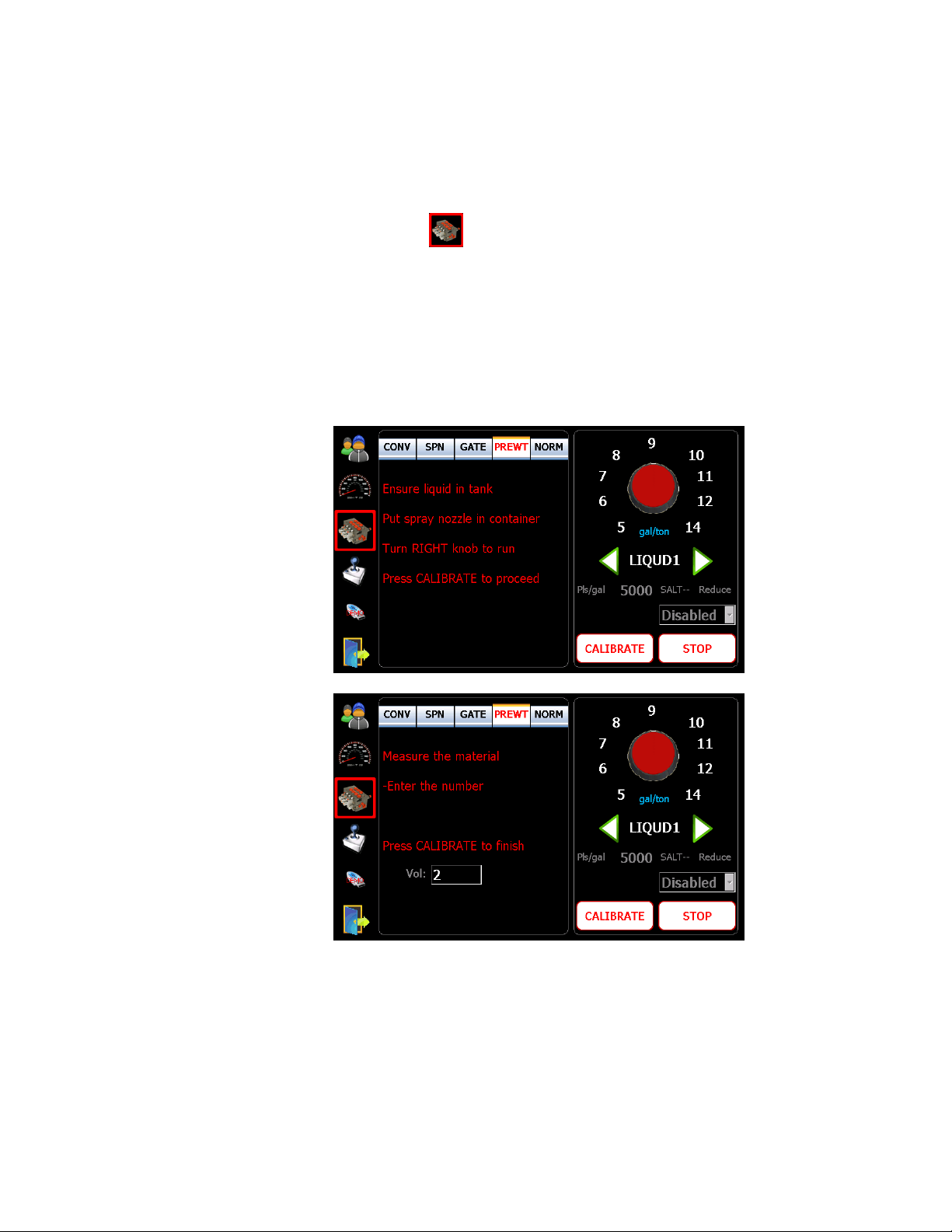
Liquid Material Calibration (Prewet or Anti
Liquid Material Calibration (Prewet or Anti----icing)
Liquid Material Calibration (Prewet or AntiLiquid Material Calibration (Prewet or Anti
icing)
icing)icing)
11/32
1. Tap on symbol and PREWET
calibration.
2. Place an adequate catch container under the liquid spray nozzle.
3. Make sure that sufficient liquid in the tank and the system is safe to run.
4. Press “CALIBRATION” button to proceed.
5. Turn PREWET Knob to run.
6. Stop when desired amount is reached.
7. Measure the liquid volume and enter the value.
8. Press “CALIBRATION” Button to complete.
PREWET/NORM
PREWETPREWET
/NORM tab to enter into liquid
/NORM/NORM
Bosch Rexroth Canada ı 07.10.2013 ı Revision 3.0
Page 12
12/32
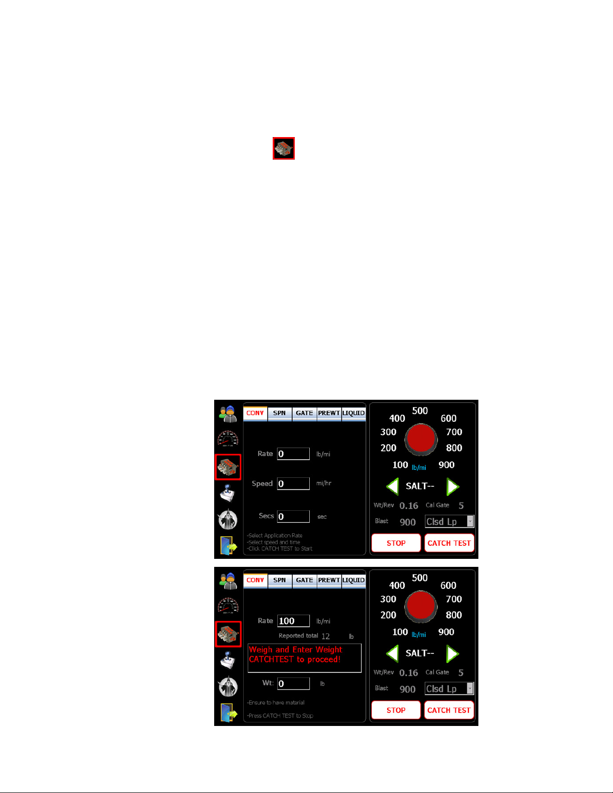
9 Material Catch Test
1. Tap on symbol to enter into the material calibration screen.
2. Place an adequate catch container under the spreader discharge chute.
3. Press “CATCH TEST” button to start, and enter the desired rate, speed and
duration (seconds) using on-screen keypad.
4. Press “CATCH TEST” button to begin material dispensing (hydraulics must be
active).
5. When dispensing is stopped, weigh the material and enter the value.
6. Press “CATCH TEST” button again to end.
7. An appropriate weight per revolution will be calculated and displayed on the
bottom right of the screen.
8. Repeat this procedure for all solid materials (use the green left and right arrows
to select material types).
9. The individual rates can be adjusted by tapping the rate and editing the value
with the keypad.
10. These same procedures apply to pre-wet and liquid.
Note: The material names can be changed by tapping on the text “SALT - -” and
using the keypad to edit.
Bosch Rexroth Canada ı 07.10.2013 ı Revision 3.0
Page 13
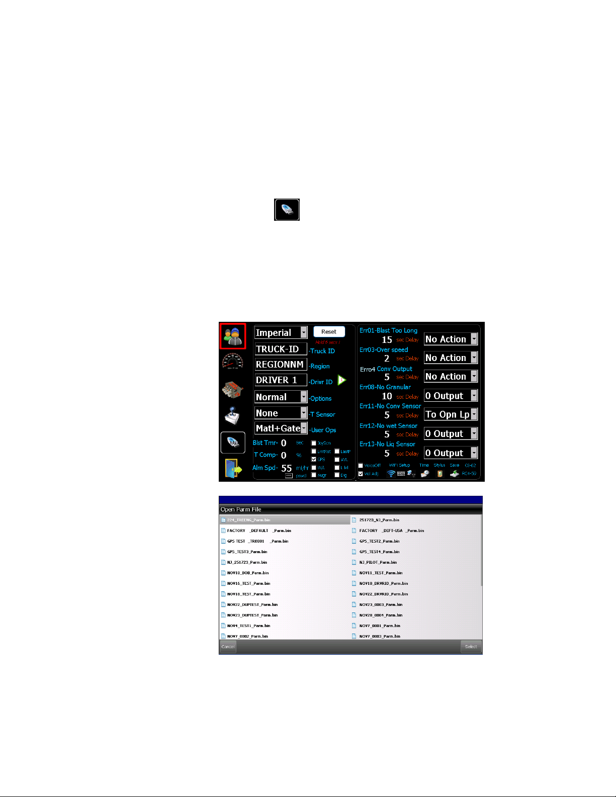
10 Load Parameters
The operation requires an USB PROGRAM key. It allows end users to load
parameters from an existing file on the USB stick.
1. Ensure an USB PROGRAM key inserted
2. Tap on USB symbol.
3. Select a file to load from the popup file window.
4. Click on the “Select” or “Cancel” button to select or cancel.
Then the popup file window would close, and red “Load” text shows up on the
USB symbol if a file is selected.
5. Tap on the Door Symbol to exit to the operation mode.
6. Turn the unit off, and on again for the new parameter to take effect.
13/32
Bosch Rexroth Canada ı 07.10.2013 ı Revision 3.0
Page 14
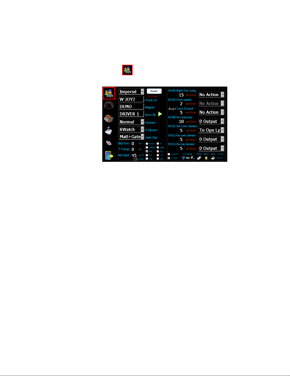
11 Advanced Features
Tap on symbol to enter into the user calibration screen. This series of
drop-down menus allow the adjustment of special features of the 550 system.
System Reset – Press and hold the preset button for 5 seconds.
WARNING: All parameters will be reset to factory defaults.
WARNING: All parameters will be reset to factory defaults.
WARNING: All parameters will be reset to factory defaults.WARNING: All parameters will be reset to factory defaults.
Temperature Sensor
Temperature Sensorssss
Temperature SensorTemperature Sensor
System Options
System Options
System OptionsSystem Options
User Options
User Options
User OptionsUser Options
without a programming key).
Blast Timer
Blast Timer
Blast TimerBlast Timer
SSSSpeed alarm
peed alarm
peed alarmpeed alarm
Temp Comp
Temp Comp
Temp CompTemp Comp
JoyScn
JoyScn
JoyScnJoyScn
LmtRst
LmtRst
LmtRstLmtRst
GPS/AVL
GPS/AVL
GPS/AVLGPS/AVL
Puck (R987380745), or AVL interface.
W/L
W/L
– Prewet and Anti-icing operation interlock with an asymmetrical valve
W/LW/L
L lvl
L lvl
– Use MAT change input as liquid level detection.
L lvlL lvl
Fr
Fr
– French version
FrFr
Auger
Auger
– Once checked the gate change is disabled
AugerAuger
LastP
LastP
– Remember the last knob positions at power up.
LastPLastP
Dig
Dig
– Disable remote Pause/Blast, and use them as digital inputs
DigDig
VoiceOff
VoiceOff
VoiceOffVoiceOff
VolAdj
VolAdj
– Allow operators to adjust volume without programming key
VolAdjVolAdj
– MATERIAL and or GATE (operators allowed to adjust
– Blast turns off automatically when time out
– alarm will sound when the set speed is exceeded.
– Temp compensation, per three degree change
– Operator screen defaults to joystick screen.
– Dump limit warning disappears once acknowldged
– GPS tracking, require a serial cable (R987376776) and a GPS receiver
– Turn off voice readout for spreader functions.
– Roadwatch, Surface Patrol
– Normal, Pattern, Air Gate, Liquid+, Cross Conv
14/32
Bosch Rexroth Canada ı 07.10.2013 ı Revision 3.0
Page 15
15/32
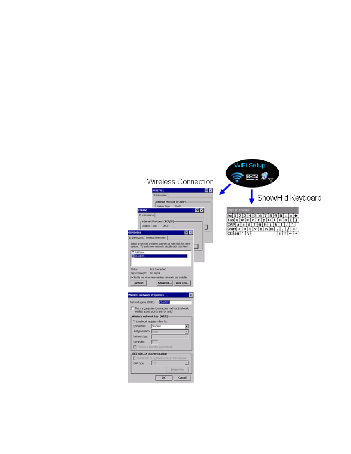
12 WiFi and GPS Tracking
If equipped with WiFi option make sure an internal or external antenna is connected
before setting it up. Similar to standard PC there are two parts that need to be set
up, Wireless Connection and Network Settings.
Wireless Connection:
Wireless Connection:
Wireless Connection:Wireless Connection:
similar to setting up a WiFi connection of a PC. A network profile needs to be set up
to allow a 550 controller to connect to the network. Appropriate security protection
is recommended for the router and the 550 controller.
Setting up connection to a router/access point. This is very
Bosch Rexroth Canada ı 07.10.2013 ı Revision 3.0
Page 16
Network Setting
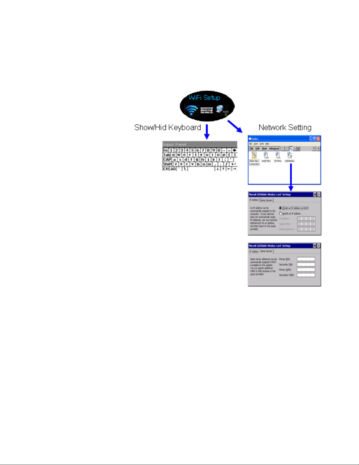
Network Setting::::
Network SettingNetwork Setting
software to communication with a CS5550/150 unit.
A static IP Address needs to be assigned for the 550 PC WiFi
16/32
GPS Tracking
GPS Tracking::::
GPS TrackingGPS Tracking
simply connecting a GPS receiver to the display unit. Here are the part numbers for
the cable and the GPS receiver puck:
R987376776, 550 Serial cable for GPS and Temp sensor
R987380745, GPS receiver
For 550 controllers it is easy to enable the GPS tracking option by
Bosch Rexroth Canada ı 07.10.2013 ı Revision 3.0
Page 17
17/32
13 Optional Modes and Operation
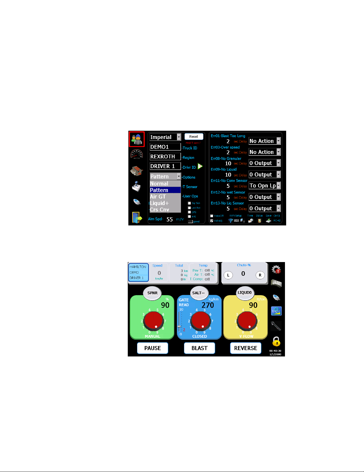
13.1 Pattern Mode - Chute Control
This mode requires a hydraulic valve and a hydraulic cylinder. It controls the
direction of a chute by moving the chute LEFT or RIGHT on the operator screen.
1. Select the
Pattern
Pattern
PatternPattern
mode under “Options” menu from USER screen.
2. Click ‘L’ and ‘R’ buttons on operator screen to move chute to the Middle position
3. Click on the value of ‘Chute-%’ to record the position with an USB PROGRAM key
inserted into USB port.
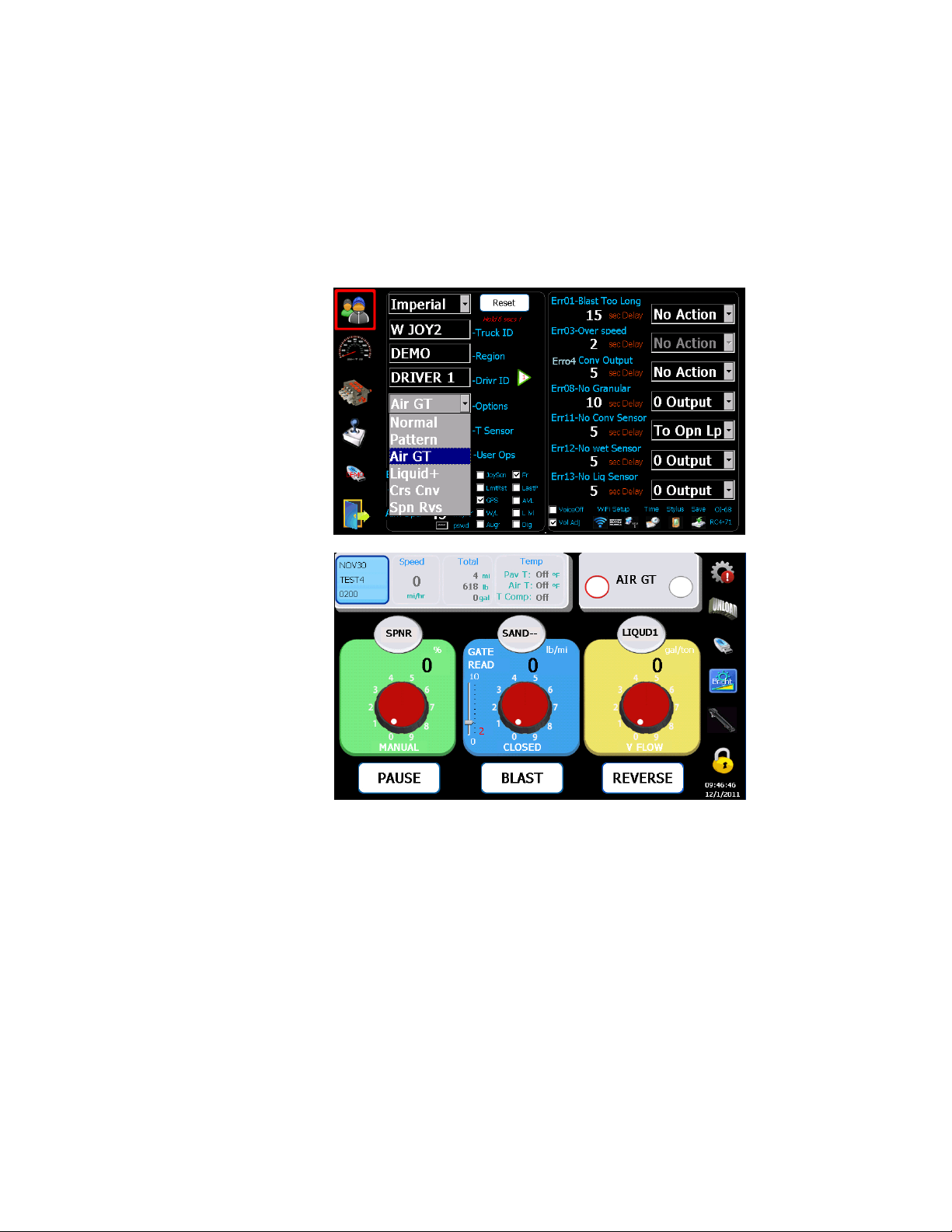
13.2 Air Gate Mode
This mode allows a two position gate control with an air cylinder for two
different materials, like SAND and SALT. It provides a digital output signal (0, 12V)
to toggle between two materials and two calibrated gate positions. When gate
Bosch Rexroth Canada ı 07.10.2013 ı Revision 3.0
Page 18
18/32
position changes the 550 controller also automatically set the gate position to the
correct calibrated gate position for the material.
1. Select the
2. Click buttons on operator screen to turn on/off Air Gate.
Air Gate
Air Gate
Air GateAir Gate
mode under “Options” menu from USER screen.
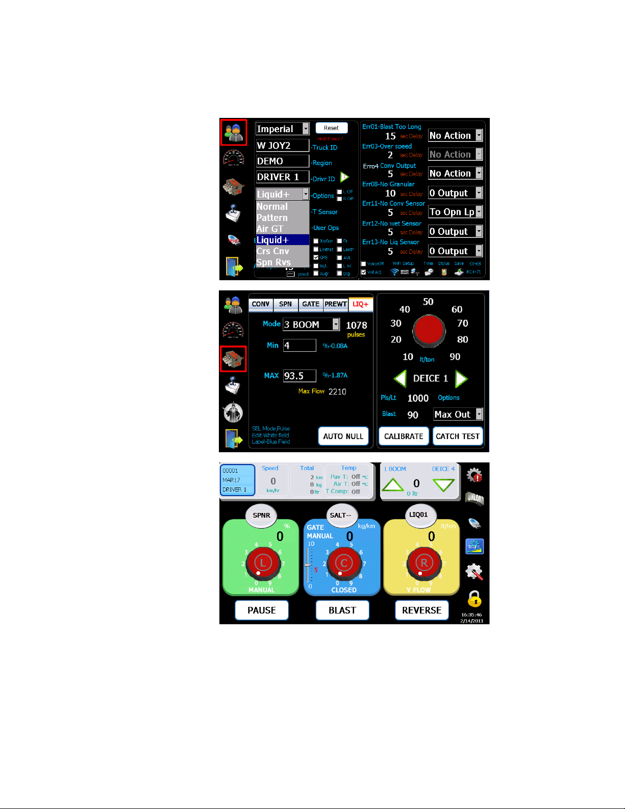
13.3 Liquid+ Mode (Solid+Prewet+3 Boom Anti-ice)
This mode allows a 550 controller to run both Solid, Prewet and Anti-icing
operations simultaneously on a single screen.
1. Select the Liquid+ under “Options
2. Click on Valve icon and then click on LIQ+
3. Set the min and max value as defined in the valve nulling procedure (on page 8).
4. Calibrate all Prewet and Anti-icing materials to be used.
5. Click L, C, R
L, C, R buttons on operator screen to turn on/off each boom.
L, C, RL, C, R
Options” menu from the USR screen.
OptionsOptions
LIQ+ tab, and select “3 BOOM”.
LIQ+LIQ+
Bosch Rexroth Canada ı 07.10.2013 ı Revision 3.0
Page 19
19/32
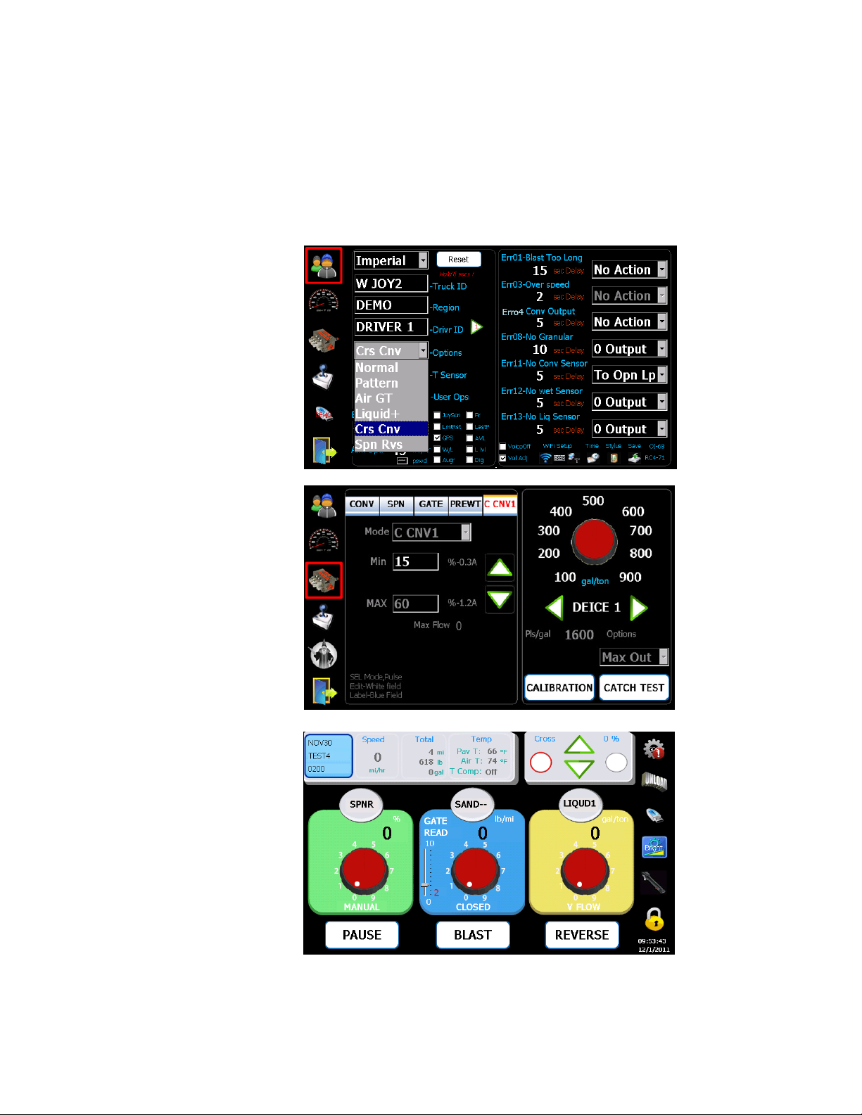
13.4 Cross Conveyor
This mode provides a proportional output and two digital outputs (Metric), and
or two proportional outputs (Imperial) to manually control a Left and a Right cross
conveyor.
Bosch Rexroth Canada ı 07.10.2013 ı Revision 3.0
Page 20
20/32
1. Select the
2. Click on Valve icon and then click on C CNV
3. Set the min and max values as defined in the valve nulling procedure (page 8).
4. Select left/right cross conveyor, click up/down buttons to adjust speed.
Crs Conv
Crs Conv
Crs ConvCrs Conv
under “Options” menu from the USER screen.
C CNV tab.
C CNV C CNV
Bosch Rexroth Canada ı 07.10.2013 ı Revision 3.0
Page 21
21/32
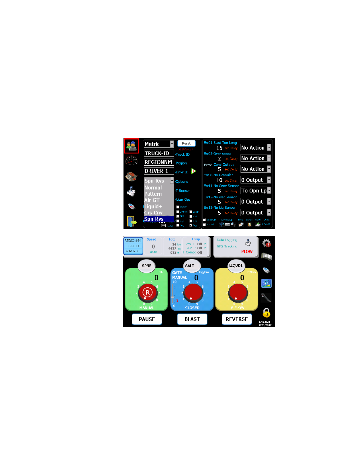
13.5 Spinner Reverse Mode
This mode allows end users to control a Spinner in either forward or reverse
direction by providing two proportional spinner outputs. When an operator click on
the RRRR button to reverse the spinner direction the controller ramps down from the
current direction and ramps up to the opposite direction.
1. Select the
2. System assume the same Min&Max for Spinner reverse output
3. Click ‘R’ button to select spinner forward or reverse operation
Spn Rvs
Spn Rvs
Spn RvsSpn Rvs
under “Options” menu from the USER screen.
13.6 Solid Reduction for Pre-wet
This feature helps to save salt usage when prewet is turned on. End users are
able to define a percentage of salt rate reduction in material configuration.
1. Select the Prewet
2. The pull-down menu for solid reduction percentage is in the bottom right of the
screen (i.e. 10%, 15%, 20%, 30%)
Prewet tab.
PrewetPrewet
Bosch Rexroth Canada ı 07.10.2013 ı Revision 3.0
Page 22
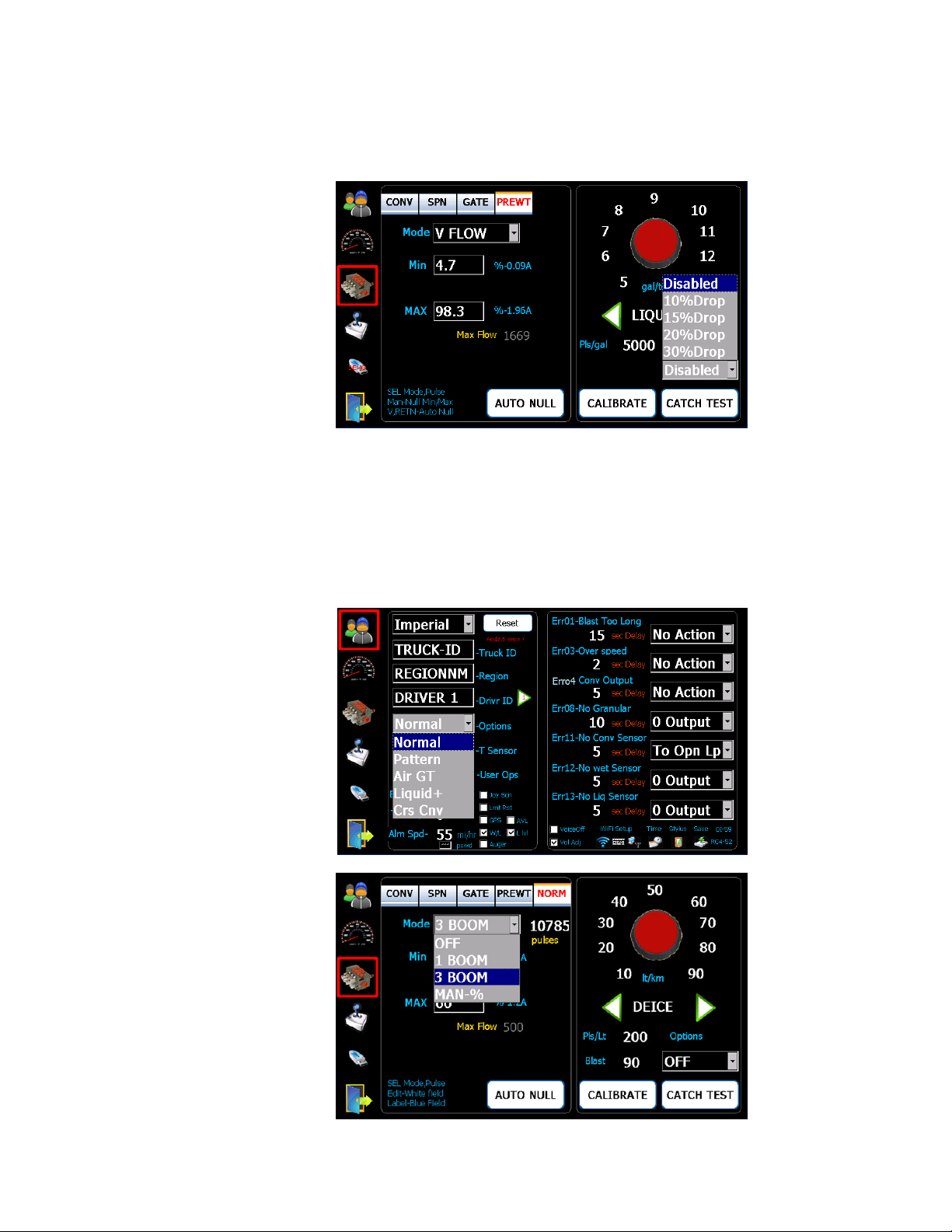
13.7 Dedicated 3 Boom Anti-ice
This mode sets the 550 controller to a dedicated Anti-ice controller. Since this
mode selection may require some IO re-initialization the controller needs to be
turned off, and turned back on.
1. Select
2. Click on Valve icon and then click on NORM
Norm
Norm
under the “Options” menu from the USER screen.
NormNorm
NORM icon, and select “3 BOOM”.
NORMNORM
22/32
Bosch Rexroth Canada ı 07.10.2013 ı Revision 3.0
Page 23
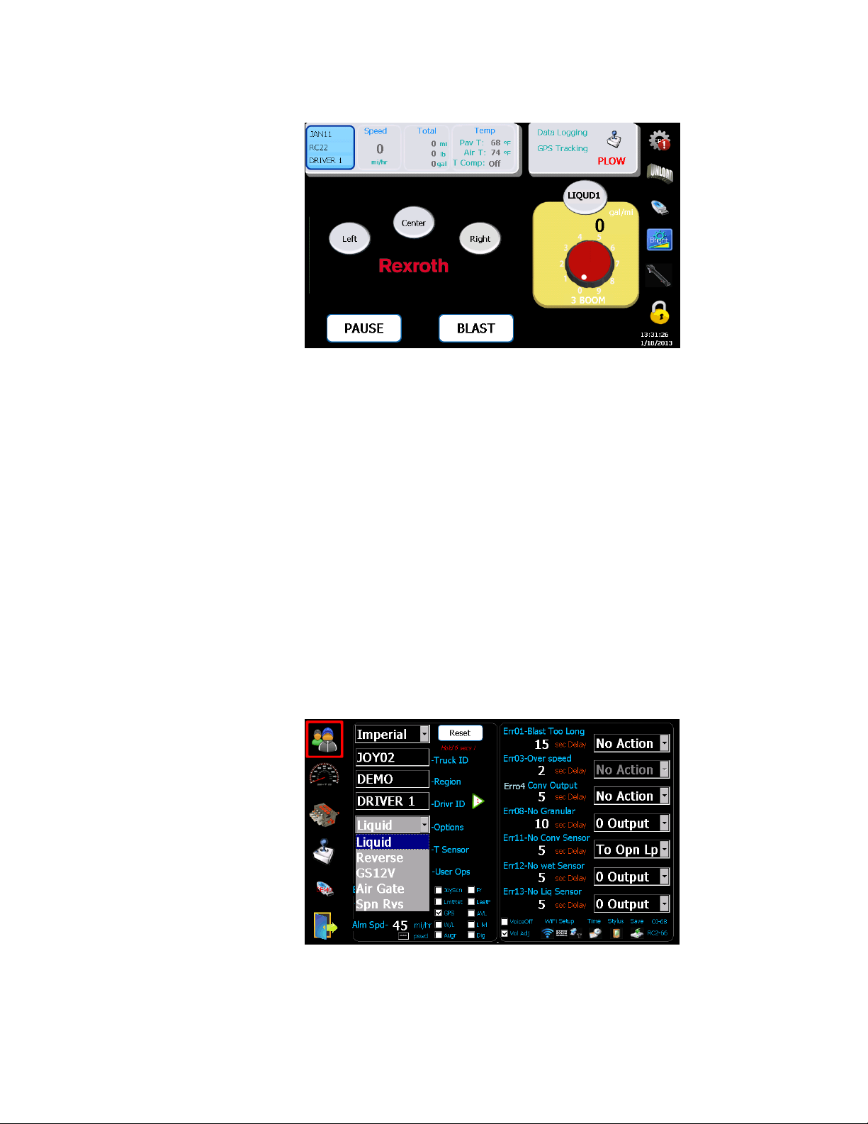
23/32
14 Optional Modes & Operation– 550Lite
The 550 Lite is a cost effective version of standard 550. It supports the following
optional functions:
Liquid
Reverse
GS12V
Air Gate
Spn Rvs
Only one of the above functions can be configured for the system.
.
14.1 Liquid – 1 Boom Anti-icing
This mode allows Conveyor, Spinner, Prewet and Anti-icing to run
simultaneously.
1. Select the
2. Click on Valve icon and then click on NORM
Liquid –––– Anti-icing
LiquidLiquid
Reverse –––– Same as the standard 550 Reverse function
ReverseReverse
GS12V –––– Enable a ground speed triggered digital output for custom use
GS12VGS12V
Air Gate –––– Same as standard 550,
Air GateAir Gate
Spn Rvs –––– Same as standard 550, see 13.5 on page 21
Spn Rvs Spn Rvs
Liquid
Liquid
mode under “Options” menu from USER screen.
LiquidLiquid
, see 13.2 on page 17
, ,
NORM icon, and select “3 BOOM”.
NORMNORM
Bosch Rexroth Canada ı 07.10.2013 ı Revision 3.0
Page 24
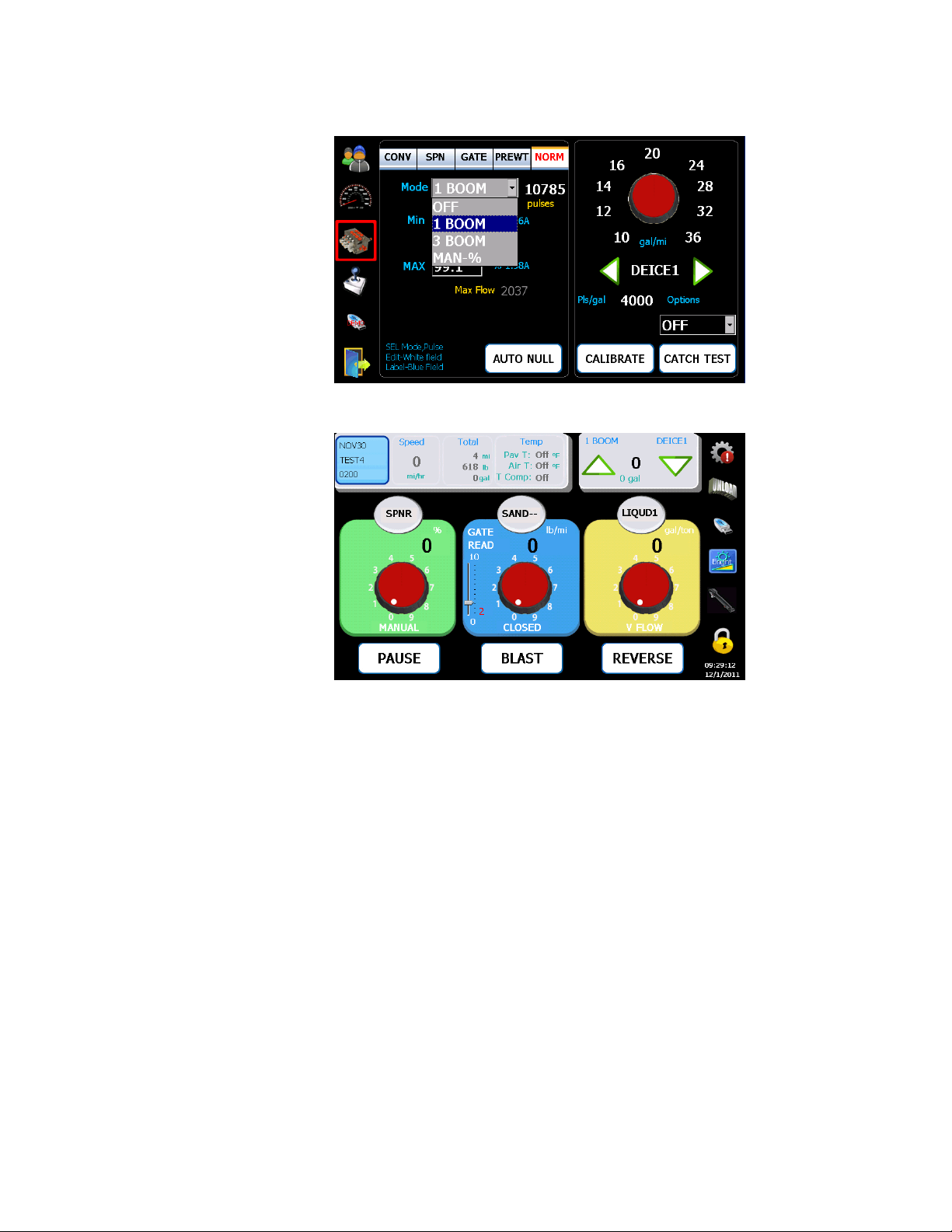
3. Press Up and Down buttons on operator screen to adjust Anti-icing rates
14.2 Liquid – Dedicated 3 Boom Anti-icing
Same as the standard 550, see 13.7
13.7 on previous page.
13.713.7
24/32
Bosch Rexroth Canada ı 07.10.2013 ı Revision 3.0
Page 25

25/32
Error Description
#
Suggested Solution
14 Error Codes
The following error messages are user configurable, both timeouts and controller
actions.
ERROR_BLAST_TOO_LONG 1 Turn off blast/time too short
ERROR_DEICE_BLST_TOO_LONG 2 Turn off blast/time too short
ERROR_OVERSPEED 3 Slow down or raise gate
ERROR_SPIN_PROP 4 Check cables, replace coil
ERROR_CONV_PROP 5 Check cables, replace coil
ERROR_CROSS1_PROP 6 Check cables, replace coil
ERROR_CROSS2_PROP 7 Check cables, replace coil
ERROR_NO_MATL_DETECT 8 Load material, check sensor
ERROR_NO_LIQ_DETECT 9 Load material, check sensor
ERROR_NO_GROUNDSPEED 10 Check cable/sensor
ERROR_NO_CONVEYOR 11 Check cable/sensor
ERROR_NO_LIQUID 12 Check cable/sensor
ERROR_NO_DEICE 13 Check cable/sensor
The following Errors are warning messages, and not user configurable.
Error 20
Error 20 - Output Non-Zero. This is a safety function to prevent the controller from
Error 20Error 20
accidentally sending an unexpected output when the controller is turned on, or
when the user leaves programming mode and enters normal operation mode. The
outputs will be kept at zero until the error condition is removed. To recover, set the
application rates to zero or exit Blast mode.
Error 21
Error 21 - Unload Not Allowed. An attempt was made to enter Unload mode while
Error 21Error 21
the truck was moving, which is not allowed. The Unload command will be ignored in
this case.
Error 22
Error 22 - BB3 System Error. This is an unrecoverable error in the RC controller. Try
Error 22Error 22
rebooting the controller to see if it goes away, otherwise report the failure to Bosch
Rexroth. This error can also occur if an attempt is made to run a joystick without
having an RCE controller present.
Bosch Rexroth Canada ı 07.10.2013 ı Revision 3.0
Page 26

26/32
Error 23
Error 23 - This is a communication failure between the RC controller and the display.
Error 23Error 23
It will show up in the logging history in the RC controller after the display is reconnected.
Error 24
Error 24 - RCE communication failure. This is a communication failure between the
Error 24Error 24
RC controller and the RCE controller in a system with a joystick. It will automatically
shut down the joysticks. The status of this communication can also be monitored
using the display item called DIG which is available by double-tapping on the gear
icon while in normal operation mode. The item called DIG at the bottom right corner
of the display should normally be zero. It will be E0 if this error occurs.
Error 25
Error 25 - Joystick 1 communication failure. This will shut down the joystick outputs,
Error 25Error 25
and will show up as a 40 in the live DIG display item.
Error 26
Error 26 - Joystick 2 communication failure. This will shut down the joystick outputs,
Error 26Error 26
and will show up as a 80 in the live DIG display item.
Error 27
Error 27 - No Gate Sensor. Gate sensor failure, most likely caused by cable break.
Error 27Error 27
This will force the gate control into Manual.
Error 28
Error 28 - Gate Position is Zero. This will occur only if the gate position is zero while
Error 28Error 28
in gate read-back mode. The conveyor will not be allowed to move until this is fixed.
Error 29
Error 29 - No Ground Speed Simulation. This is just an information message to
Error 29Error 29
indicate that ground speed simulation mode has been stopped.
Error 30
Error 30 - Under-Application: Spinner. The spinner cannot meet the desired RPM
Error 30Error 30
setpoint. This should not happen in manual mode, but could happen if the spinner is
in PPS mode and the ground speed is high.
Error 31
Error 31 - Under-Application: Conveyor. The conveyor cannot meet the desired RPM
Error 31Error 31
setpoint. Caused by too high application rate or too high ground speed or incorrect
calibration.
Error 32
Error 32 - Under-Application: Pre-Wet. The pre-wet pump cannot meet the desired
Error 32Error 32
flow setpoint. Caused by too high application rate or too high ground speed or
incorrect calibration.
Error 33
Error 33 - Under-Application: Anti-Ice. The anti-ice pump cannot meet the desired
Error 33Error 33
flow setpoint. Caused by too high application rate or too high ground speed or
incorrect calibration.
Error 34
Error 34 - Over-Application: Conveyor. The solid application rate is above setpoint.
Error 34Error 34
Most likely caused by a minimum null value for conveyor output that is too high, so
the conveyor never stops.
Error 35
Error 35 - Over-Application: Pre-Wet. The pre-wet application rate is above setpoint.
Error 35Error 35
Most likely caused by a minimum null value for the pre-wet pump output that is too
high, so the pump never stops.
.
. .
Error 36
Error 36 - Over-Application: Anti-Ice. The anti-ice application rate is above setpoint.
Error 36Error 36
Most likely caused by a minimum null value for the anti-ice pump output that is too
high, so the pump never stops.
Bosch Rexroth Canada ı 07.10.2013 ı Revision 3.0
Page 27

27/32
Error 37
Error 37 - Calibration: Ground-Speed Pulses Too Low. Calculated pulses per km is
Error 37Error 37
too low during calibration. Possibly caused by no sensor feedback, or try
recalibrating the ground speed sensor.
Error 38
Error 38 - Spinner Maximum RPM Too Low. During auto nulling, the calculated
Error 38Error 38
maximum RPM was too low, most likely caused by no sensor feedback.
Error 39
Error 39 - Conveyor Maximum RPM Too Low. During auto nulling, the calculated
Error 39Error 39
maximum RPM was too low, most likely caused by no sensor feedback.
Error 40
Error 40 - Pre-Wet Maximum Hz Too Low. During auto nulling, the calculated
Error 40Error 40
maximum Hz was too low, most likely caused by no sensor feedback.
Error 41
Error 41 - Anti-Ice Maximum Hz Too Low. During auto nulling, the calculated
Error 41Error 41
maximum Hz was too low, most likely caused by no sensor feedback.
Error 42
Error 42 - Wrong Spinner Control Mode. An attempt was made to perform auto
Error 42Error 42
nulling of a spinner while it was in manual.
Error 43
Error 43 - Wrong Conveyor Control Mode. Not Used.
Error 43Error 43
Error 44
Error 44 - Wrong Pre-Wet Control Mode. An attempt was made to perform auto
Error 44Error 44
nulling, or volume calibration, of a pre-wet pump while it was in manual.
Error 45
Error 45 - Wrong Anti-Ice Control Mode. An attempt was made to perform auto
Error 45Error 45
nulling, or volume calibration, of an anti-ice pump while it was in manual. This error
could also be caused by an I/O conflict between a cross conveyor mode and the
anti-ice pump output, in which case the anti-ice pump will be disabled.
Error 46
Error 46 - Wrong Cross-Conveyor Mode. An attempt was made to go into Reverse
Error 46Error 46
while this output was being used by a cross-conveyor mode. The Reverse command
will be ignored in this case. Could also be caused by attempting to use gm/sq.m.
mode while there was an I/O conflict with a Cross-Conveyor CA mode, in this case
gm/sq.m. mode will not be allowed. Could also be caused by attempting to use
closed-loop gate control while in Cross-Conveyor US mode or Liquid-Plus mode, in
which case the gate control will be forced into gate readback mode.
Error 47
Error 47 - Wt. per Revolution Too Low. During conveyor weight calibration, the
Error 47Error 47
calculated weight per revolution was too low, most likely caused by typing in zero
for the weight.
Error 48
Error 48 - Wt. per Revolution Too High. During conveyor weight calibration, the
Error 48Error 48
calculated weight per revolution was too high, most likely caused by no conveyor
sensor feedback.
Error 49
Error 49 - Pre-Wet Pulses per Gallon Too Low. During calibration of pre-wet volume
Error 49Error 49
output, the pulses/gal was too low, most likely caused by no flow sensor feedback.
Error 50
Error 50 - Pre-Wet Pulses per Gallon Too Hi. During calibration of pre-wet volume
Error 50Error 50
output, the pulses/gal was too high, most likely caused by typing in zero for the
volume.
Bosch Rexroth Canada ı 07.10.2013 ı Revision 3.0
Page 28

28/32
Error 51
Error 51 - Anti-Ice Pulses per Gallon Too Low. During calibration of anti-ice volume
Error 51Error 51
output, the pulses/gal was too low, most likely caused by no flow sensor feedback.
Error 52
Error 52 - Anti-Ice Pulses per Gallon Too Hi. During calibration of anti-ice volume
Error 52Error 52
output, the pulses/gal was too high, most likely caused by typing in zero for the
volume.
Error 53
Error 53 - Spinner mm at zero RPM too Low. During calibration of the relationship
Error 53Error 53
between spinner RPM and spinner spread width, a value of 0 mm at zero RPM was
used.
Error 54
Error 54 - Spinner mm per RPM too Low. During calibration of the relationship
Error 54Error 54
between spinner RPM and spinner spread width, a value of maximum spread width
was used that was less than the mm at zero RPM.
Error 55
Error 55 - Gate Movement Too Low. During calibration of gate maximum and
Error 55Error 55
minimum position, the difference between minimum and maximum height was less
than 1 inch.
Error 56
Error 56 - Gate Zero in Manual. While in manual gate control mode, the operating
Error 56Error 56
gate position was specified to be zero.
Error 57
Error 57 - Gate at Calibration Too Low. While calibrating the weight per revolution
Error 57Error 57
for a specific material, the gate position at calibration was specified to be zero.
Error 58
Error 58 - Spinner PPR Too Low. A value of zero was used for spinner pulses per
Error 58Error 58
revolution.
Error 59
Error 59 - Conveyor PPR Too Low. A value of zero was used for conveyor pulses per
Error 59Error 59
revolution.
Error 60
Error 60 - Spinner Output Range Too Low. The difference between maximum and
Error 60Error 60
minimum spinner nulling values was less than 5%.
Error 61
Error 61 - Conveyor Output Range Too Low. The difference between maximum and
Error 61Error 61
minimum conveyor nulling values was less than 5%.
Error 62
Error 62 - Cross Conveyor 1 Output Range Too Low. The difference between
Error 62Error 62
maximum and minimum cross conveyor nulling values was less than 5%.
Error 63
Error 63 - Cross Conveyor 2 Output Range Too Low. The difference between
Error 63Error 63
maximum and minimum cross conveyor nulling values was less than 5%.
Error 64
Error 64 - Pre-Wet Output Range Too Low. The difference between maximum and
Error 64Error 64
minimum pre-wet nulling values was less than 5%.
Error 65
Error 65 - Anti-Ice Output Range Too Low. The difference between maximum and
Error 65Error 65
minimum anti-ice nulling values was less than 5%.
Error 66
Error 66 - Joystick 1 Output Range Too Low. The difference between maximum and
Error 66Error 66
minimum joystick nulling values for one of the six outputs was less than 5%.
Bosch Rexroth Canada ı 07.10.2013 ı Revision 3.0
Page 29

29/32
Error 67
Error 67 - Joystick 2 Output Range Too Low. The difference between maximum and
Error 67Error 67
minimum joystick nulling values for one of the six outputs was less than 5%.
Error 68
Error 68 - Theoretical Maximum Conveyor RPM Too High. Based on the specified
Error 68Error 68
application rate setpoints, and the maximum ground speed, the maximum
theoretical conveyor RPM required has been calculated to be more than twice the
actual conveyor capacity, which will lead to serious under-application problems. The
actual controller RPM setpoint will be clamped at this value to prevent the
controller from becoming unstable, and the conveyor should be re-calibrated to
determine the source of the problem.
Error 69
Error 69 - Theoretical Maximum Pre-Wet Hz Too High. Based on the specified
Error 69Error 69
application rate setpoints, and the maximum ground speed, the maximum
theoretical pre-wet pump flow required has been calculated to be more than twice
the actual pump capacity, which will lead to serious under-application problems.
The actual pump flow setpoint will be clamped at this value to prevent the
controller from becoming unstable, and the pre-wet pump should be re-calibrated to
determine the source of the problem.
Error 70
Error 70 - Theoretical Maximum Anti-Ice Hz Too High. Based on the specified
Error 70Error 70
application rate setpoints, and the maximum ground speed, the maximum
theoretical anti-ice pump flow required has been calculated to be more than twice
the actual pump capacity, which will lead to serious under-application problems.
The actual pump flow setpoint will be clamped at this value to prevent the
controller from becoming unstable, and the anti-ice pump should be re-calibrated to
determine the source of the problem.
Bosch Rexroth Canada ı 07.10.2013 ı Revision 3.0
Page 30
30/32
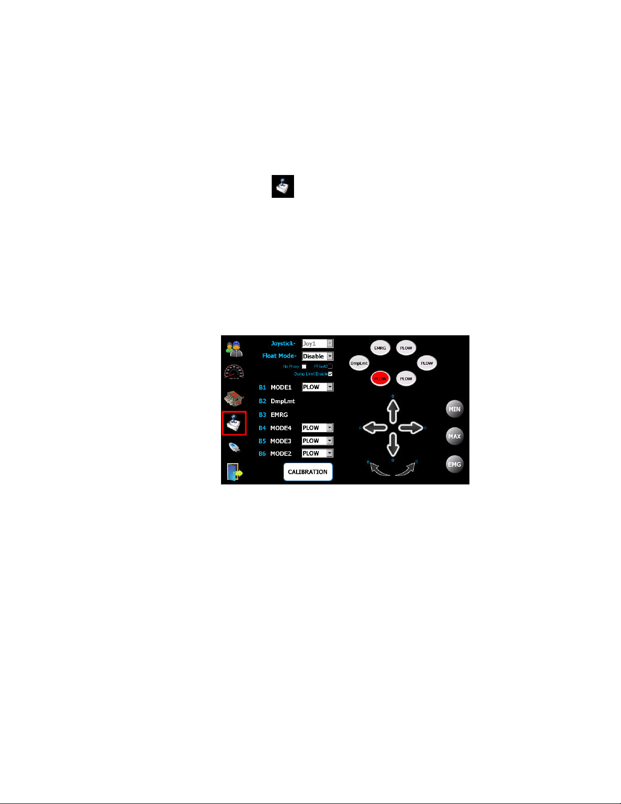
15 Joystick Calibration
15.1 Solenoid Nulling
1. Start vehicle and achieve full pump flow.
2. Tap on Joystick symbol.
3. Press “CALIBRATION” button and press a mode button on the
joystick to select a desired mode to adjust.
4. Move the joystick slightly until the hydraulic actuator moves slowly – press
“Min” while the stick is deflected.
5. Move the joystick until the actuator moves at a safe maximum speed – press
“Max”.
6. Repeat this for all axis’, directions and modes.
Press “CALIBRATION” button again to save all changes.
15.2 Emergency (Panic Button) – If Equipped
1. Select the desired mode on the joystick and pull the joystick in the direction that
the emergency button should activate.
2. Press the round “EMG” button while the stick is deflected.
Any mode or direction can be assigned to Panic Button. In operation mode when the
Panic button is pushed in conjunction with the Deadman trigger, the selected
function(s) will activate simultaneously.
This joystick calibration is only required when a multifunction CANbus Joystick
Console is included with the system.
All the mode names and special functions will be configured by the factory. Only
solenoid nulling may be required.
Bosch Rexroth Canada ı 07.10.2013 ı Revision 3.0
Page 31
31/32
16 Advanced Joystick Set-up
16.1 Power Float
If equipped, the Power Float mode can also be edited.
Resetting
Resetting
ResettingResetting
Re-engages float when the joystick is returned to neutral.
Non
Non----resetting
resetting
NonNon
resettingresetting
The button must be pushed to re-enable the float after the stick is deflected.
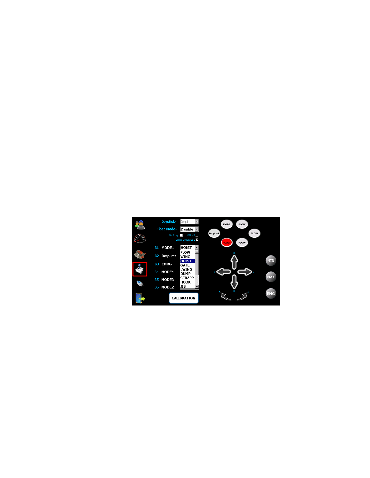
16.2 Function Labels
All the joystick button names and function will be preset by the factory. The joystick
button names can be edited via the pull-down selection menus.
B1 is at the bottom left location and the buttons count up clockwise.
Note: Editing the names of the functions does not re-allocate the outputs on the
valve cable. They are fixed and defined in the valve layout for the specific system.
17 Warning
This glass LCD touch screen display has been extensively tested and validated
against its intended use. This glass could crack and break if the display is dropped
on to a hard surface or receives substantial impact. If the glass chips or cracks,
discontinue use and contact Bosch Rexroth Canada to have it replaced - do not
Bosch Rexroth Canada ı 07.10.2013 ı Revision 3.0
Page 32

32/32
touch or attempt to remove the broken glass. Any misuse/abuse causing damage,
whether intended or not, will become the sole responsibility of the owner/buyer
which will render the warranty of this product, void.
Notes:
Bosch Rexroth Canada ı 07.10.2013 ı Revision 3.0
 Loading...