

Page 1

Hydraulic Cylinder
NFPA Industrial Type
Model CDT1/CGT1
Series 1X
Nominal pressure: Up to 1,500 psi maximum
RA 17038/02.13
Replaces: 11.12
1/44
Table of contents
Contents Page
Technical Data 2
Cylinder Weight 2
Area, Forces, Flow 3
Stroke Tolerances 3
Ordering Details 4
Piston Rod Versions 6
Mounting Type Overview 7
Dimensional Data 8
Double Rod Cylinders 26
Mounting Accessories 28
Cylinder Options 33
Cylinder Application Data 37
Spare Parts 44
Features
– Duty, up to 1,500 psi (see chart on page 2)
– Standards, meets or exceeds all JIC and NFPA requirements
– Bore Sizes, 1-1/2” - 8”
– Piston Rods, 1/2" - 5-1/2”
– Mountings,18 standard NFPA mountings
– Ports, SAE o-ring straight thread ports
– Stroke, standard strokes furnished in 1/8” increments. Normal
stroke tolerance + 1/16” / -0”. Closer stroke tolerances available; consult factory.
– Rod End Threads, standard KK1 male and female threads plus
KK2 oversize male thread. Other rod end styles optional.
– Cushions, available for all bore sizes, at either or both ends.
Project planning software
Interactive Catalog System
Online www.boschrexroth.com/ics
Page 2

2/44 Bosch Rexroth Corp. | Industrial Hydraulics CDT1/CGT1 | RA 17038/02.13
Technical Data (for applications outside these parameters, please consult factory)
Standards:
Meets or exceeds all JIC and NFPA requirements.
Operating Pressures (PSI) by Cylinder
Bore Sizes*
Nominal pressure: up to 1,500 psi
With extreme shock loads the mounting styles and piston rod
threads have to be considered, taking the fatigue limits into
account.
Maximum operating pressure up to: 1,500 psi
Installation position: Various
Pressure fluid:
Mineral oils (HL, HLP)
Phosphate ester (HFD-R) (–4°F to 300°F)
HFA (41°F to 131°F)
Water glycol HFC (–4°F to 140°F)
Hydraulic fluid temperature range: (-4°F to 176°F)
Viscosity range: 32 to 1760 ssu
Max. psi
Cylinder Standard (max duty
Bore Ø Rod Ø servere
(inches) (inches) service)
1-1/2 1 1,500
2 1 1,500
2-1/2 1 1,500
3-1/4 1 1,500
4 1-3/8 1,000
5 1-3/4 750
6 1-3/4 750
8 2 500
Degree of contamination:
Max. permissible degree of contamination of the pressure fluid
is to NAS 1638 class 10.
We therefore recommend a filter with a minium retention rate
of
β
≥ 75.
10
Stroke speed: 20 in/sec
(dependent on the connection port)
*1) For double rod cylinders, see page 26.
Air bleed standard: Secured against removal
2" - 8" bore sizes only
Acceptance:
Each cylinder is tested to Bosch Rexroth standards.
Cylinders, outside the above parameters are also available.
Consult factory
For applications above 230°F specify a non studded piston
rod end and advise operating temperature before ordering.
Under no-load conditions, a minimum pressure of 150 PSI is
recommended for single rod cylinders. In case of lower pressures or double rod cylinders, please consult factory.
*2) Exceptions to 1,500 psi rating:
a) MF1 and MF2 have maximum operating pressures
of 1,000 psi for 1-1/2" through 4" bore sizes
b) A 2.5" bore with a 5/8" rod has a maximum pressure
rating of 1,000 psi
3) Consult factory for other pressure ratings than
shown above.
4) For stroke lengths above 60 inches, working pressure
may be derated according to buckling load limits.
Consult factory.
Approximate Uncrated CDT1 Hydraulic Cylinder Weights (lbs.)*
Cylinder Bore 1.5 2 2.5 3.25 4 5 6 8
Zero Stroke 5 7 12 20 30 45 70 100
Add Per Inch of Stroke .3 .4 .6 .8 .9 1.0 1.5 2.0
* Weights based on standard (first) rod sizes. Add 10% to cover additional weight for crating.
Project planning software ICS (Interactive Catalog System)
The ICS (Interactive Catalog System) is a selection and project
planning tool for hydraulic cylinders. The ICS allows designers
of machines and systems to quickly and reliably find the perfect
hydraulic cylinder solution through logic-guided inquiries. This
software helps to solve design and project planning tasks more
quickly and efficiently. After having been guided through the
product selection, the user quickly and reliably gets the exact
technical date of the selected component as well as 2D and
3D CAD data in the correct file format for all common CAD
systems. This allows users to reduce costs while increasing
their competitiveness.
The ICS can be accessed at www.boschrexroth.com/ics.
Page 3

RA 17038/02.13 | CDT1/CGT1 Industrial Hydraulics | Bosch Rexroth Corp. 3/44
F
1
F
3
q
V3
A
3
A
1
F
2
A
2
q
V1
q
V2
Areas, Forces, Flows (dimensions in inches)
Piston Area Areas Force at 500 psi
1)
Flow at 4”/s
2)
Bore rod ratio Piston Rod Annulus Push Regen. Pull Out Regen. In
j A
A
1
A
2
F
3
F
1
F
2
q
3
q
V1
q
V2
V3
Ø in. Ø in. A1/A3 in.2 in.2 in.2 Lb. Lb. Lb. gpm gpm gpm
1.500 0.625 1.21 1.77 0.31 1.46 885 154 731 1.84 0.32 1.52
1.000 1.80 0.79 0.98 392 493 0.82 1.02
0.625 1.11 0.31 2.83 154 1,416 0.32 2.94
2.000 1.000 1.33 3.14 0.79 2.35 1,570 392 1,178 3.26 0.82 2.44
1.375 1.89 1.48 1.66 745 825 1.54 1.72
0.625 1.07 0.31 4.60 154 2,301 0.32 4.78
2.500 1.000 1.19 4.91 0.79 4.12 2,455 392 2,063 5.10 0.82 4.28
1.375 1.43 1.48 3.43 745 1,710 1.54 3.56
1.750 1.96 2.40 2.51 1,205 1,250 2.49 2.61
1.000 1.11 0.79 7.51 392 3,758 0.82 7.80
3.250 1.375 1.21 8.30 1.48 6.82 4,150 745 3,405 8.62 1.54 7.08
1.750 1.40 2.40 5.90 1,205 2,945 2.49 6.13
2.000 1.60 3.14 5.16 1,570 2,580 3.26 5.36
1.000 1.07 0.79 11.78 392 5,893 0.82 12.23
1.375 1.13 1.48 11.09 745 5,540 1.54 11.51
4.000 1.750 1.24 12.57 2.40 10.17 6,285 1,205 5,080 13.05 2.49 10.56
2.000 1.33 3.14 9.43 1,570 4,715 3.26 9.79
2.500 1.64 4.91 7.66 2,455 3,830 5.10 7.95
1.000 1.04 0.79 18.85 392 9,428 0.82 19.58
1.375 1.08 1.48 18.16 745 9,075 1.54 18.86
1.750 1.13 2.40 17.24 1,205 8,615 2.49 17.91
5.000 2.000 1.19 19.64 3.14 16.50 9,820 1,570 8,250 20.40 3.26 17.14
2.500 1.33 4.91 14.73 2,455 7,365 5.10 15.30
3.000 1.56 7.07 12.57 3,535 6,285 7.35 13.05
3.500 1.96 9.62 10.02 4,810 5,010 9.99 10.41
1.375 1.06 1.48 26.77 745 13,390 1.54 27.81
1.750 1.09 2.40 25.85 1,205 12,930 2.49 26.86
2.000 1.13 3.14 25.11 1,570 12,565 3.26 26.09
6.000 2.500 1.21 28.25 4.91 23.34 14,135 2,455 11,680 29.35 5.10 24.25
3.000 1.33 7.07 21.18 3,535 10,600 7.35 22.00
3.500 1.51 9.62 18.63 4,810 9,325 9.99 19.36
4.000 1.80 12.57 15.68 6,285 7,850 13.05 16.30
1.375 1.03 1.48 48.79 745 24,390 1.54 50.68
1.750 1.05 2.40 47.87 1,205 23,930 2.49 49.73
2.000 1.06 3.14 47.13 1,570 23,565 3.26 48.96
2.500 1.11 4.91 45.36 2,455 22,680 5.10 47.12
8.000 3.000 1.16 50.27 7.07 43.20 25,135 3,535 21,600 52.22 7.35 44.87
3.500 1.23 9.62 40.65 4,810 20,325 9.99 42.23
4.000 1.33 12.57 37.70 6,285 18,850 13.05 39.17
4.500 1.49 15.91 34.36 7,950 17,185 16.53 35.69
5.000 1.64 19.63 30.64 9,820 15,315 20.39 31.83
5.500 1.89 23.76 26.51 11,880 13,255 24.68 27.54
Note
1)
Theoretical force
(efficiency not taken into account)
2)
Stroke velocity
Stroke Tolerances
Stroke tolerances result from the cylinder head, cylinder base, cylinder tube, piston and piston rod. The stroke tolerance for all piston
diameters and stroke lengths is +1/16" / -0". Tighter stroke tolerances can be requested, however, details regarding the operating
pressure and operating temperature must be stated.
Stroke lengths Stroke tolerances
≤ 120" (refer to pg. 41 for buckling loads) +1/16" / -0"
Page 4

4/44 Bosch Rexroth Corp. | Industrial Hydraulics CDT1/CGT1 | RA 17038/02.13
Ordering Details
T1 Z 1X
Single rod cylinder = CD
Double rod cylinder = CG
Series = T1
Mounting types
Rectangular flange at head = MF1
Rectangular flange at cap = MF2
Square flange at head = MF5
Square flange at cap = MF6
Clevis mounting = MP1
Fixed pivot = MP3
Pivot Mount w/spherical bearing = MP5
Side lug = MS2
Centerline lugs mountings = MS3
Side tapped = MS4
End lugs = MS7
Trunnion at head = MT1
Trunnion at cap = MT2
Trunnion at intermediate position
Basic version = MX0
Extended tie rods, both ends = MX1
Extended tie rods, at cap = MX2
Extended tie rods, at head = MX3
Bore Dia. Ø 1.50 to 8.00 inch
Piston rod Ø 0.63 to 5.50 inch
7)
Stroke length in inches (ex. 12.00)
Design principle
Head and cap connected by tie rods = Z
Series
10 to 19 unchanged installation and connection dimensions = 1X
Port connections/ types
SAE straight thread port (ISO 11926-1) = S
NPT pipe tread port = U
Special (specify) = X
Remarks:
1)
Only 5/8" to 4" diameter piston rods are case hardened and hard
chrome plated. Above 4" diameter piston rods are chrome plated only.
2)
With extreme shock loads the piston rod threads have to be selected,
taking the fatigue limits into account. Rod end clevis, installed parts,
etc. must always be firmly clamped against the piston rod shoulder.
3)
State XV dimensions in inches in clear text.
4)
Not available on 1-1/2"-2-1/2" bore size.
5)
See page 34 for exceptions.
6)
Fixed cushions on all 1-1/2" bore sizes both ends.
Fixed cushions on 2" bore / 1-3/8" rod, 2-1/2" bore / 1-3/4" rod and
3-1/4" bore / 2" rod sizes both ends
7)
For cylinders with stop tube, the stroke in the model code is the effec-
tive stroke.
3)
= MT4
*
Further details in clear text
Option 2
W = Without options
K = Thrust key
S = Stop tube (specify length)
Y =
state length in inches in clear text
X = Multiple or other selections,
specify in clear text
Option 1
W = Without options
E = Proximity switch, both ends
A = Test point, both sides
X = Multiple or other selections,
specify in clear text
Seal version
Suitable for mineral oil to
DIN 51 524 HL, HLP and HFA
M = Polyurethane seal system
T* = Servo quality/reduced friction
F* = BUNA-N seal system for HFC
Suitable for phosphate ester HFD-R
V* = Flourocarbon seal system
End position cushioning
U = Without
D = Both sides, adjustable
S = Rod side, adjustable
K = Cap side, adjustable
Piston rod end
H = Small male thread KK1
D = Intermediate male thread KK2
E = Female thread KK1
T = S.A.F.E., rod end
X = Special (specify)
Piston rod version
H = Case hardened and hard chromium plated
S = 17-4 PH stainless steel
Port connection / location at cap
1 =
2 =
3 =
4 =
1
4
Viewed on piston rod
2
3
Port connection / location at head
1 =
2 =
3 =
4 =
1
4
2
3
Viewed on piston rod
Additional piston rod ext.
4)
5)
6)
2)
1)
* Not recommended for load holding applications. Consult factory for
load holding options.
Page 5

RA 17038/02.13 | CDT1/CGT1 Industrial Hydraulics | Bosch Rexroth Corp. 5/44
Sealing System
"M" Polyurethane seal system (standard)
"T"* Seal system for low friction applications (available)
"F"* Standard seal system for HFC (water glycol) (available)
"V"* Seal system for (phosphate ester) (available)
* - not recommended for load holding applications.
Consult factory for load holding options
Cushioning System (optional) *
Patented Exact-a-just™ cushioning provides accurate micrometer adjustment
2
1
1. Double lip wiper
2. U-cup rod seal
1
1. Double lip wiper
2. PTFE step seals
22
4
3
4
5
3. Double acting piston seal
4. Wear bands
5. Piston threaded and sealed
to piston rod with permanent
adhesive and mechanically
secured with a set screw.
4
3
4
5
3. Low friction piston seal
4. Wear bands
5. Piston threaded and sealed
to piston rod with permanent
adhesive and mechanically
secured with a set screw.
Exact-a-just™ cushioning permits adjustment over a wide range
of settings for faster cycle times
Results in reduced maintenance costs, reduced internal and
external shock, and softer cushioning stops
May be supplied at head, cap, or both ends
*
Fixed cushions on all 1-1/2" bore sizes both ends.
Fixed cushions on 2" bore / 1-3/8" rod, 2-1/2" bore / 1-3/4" rod and
3-1/4" bore / 2" rod sizes both ends
Connection Port and Secured Air Bleed (standard)
ISO 11926-1 SAE straight thread (standard)
For other port options consult factory
To provide safety and prevent accidents, patented air bleed is
secured against unscrewing (standard on 2" - 8" bore sizes, not
available on 1-1/2" bore sizes)
Air bleed ports can become an alternate connection for a
pressure test fitting (optional) (not available on 1-1/2" bore sizes)
Also not available on head end of 2" bore / 1-3/8" rod and
2-1/2" bore / 1-3/4" rod sizes
Exact-a-just™ cushioning
Alternate pressure test fitting
Page 6

6/44 Bosch Rexroth Corp. | Industrial Hydraulics CDT1/CGT1 | RA 17038/02.13
Piston Rod Versions
Male Rod End
Option H & D
Female Rod End
Option E
S.A.F.E. Rod End
Option T
D (width across flats)
Rod Thread Options:
Standard KK1 Male furnished when not specified.
Male thread available in KK1 and KK2 thread sizes.
KK1 studded male rod end standard for 5/8", 1" & 1-3/8" rod dia.
Female thread available in KK1 thread size only.
Piston Rod End
MM B
Rod A +0.000 C D KK1 KK2 NA AC AD AE AF WG
Diameter -0.002
0.625 0.75 1.124 0.38 0.50 7/16 - 20 1/2 - 20 0.56 1.13 0.63 0.250 0.375 1.75
1.000 1.13 1.499 0.50 0.88 3/4 - 16 7/8 - 14 0.94 1.50 0.94 0.375 0.688 2.38
1.375 1.63 1.999 0.63 1.13 1 - 14 1-1/4 - 12 1.31 1.75 1.06 0.375 0.875 2.75
1.750 2.00 2.374 0.75 1.50 1-1/4 - 12 1-1/2 - 12 1.69 2.00 1.31 0.500 1.125 3.13
2.000 2.25 2.624 0.88 1.69 1-1/2 - 12 1-3/4 - 12 1.94 2.63 1.69 0.625 1.375 3.75
2.500 3.00 3.124 1.00 2.06 1-7/8 - 12 2-1/4 - 12 2.38 3.25 1.94 0.750 1.750 4.50
3.000 3.50 3.749 1.00 2.63 2-1/4 - 12 2-3/4 - 12 2.88 3.63 2.44 0.875 2.250 4.88
3.500 3.50 4.249 1.00 3.00 2-1/2 - 12 3-1/4 - 12 3.38 4.38 2.69 1.000 2.500 5.63
4.000 4.00 4.749 1.00 3.38 3 -12 3-3/4 - 12 3.88 4.50 2.69 1.000 3.000 5.75
4.500 4.50 5.249 1.00 SH1* 3-1/4 - 12 4-1/4 - 12 4.38 5.25 3.19 1.500 3.500 6.50
5.000 5.00 5.749 1.00 SH1* 3-1/2 - 12 4-3/4 - 12 4.88 5.38 3.19 1.500 3.875 6.63
5.500 5.50 6.249 1.00 SH1* 4 - 12 5-1/4 - 12 5.38 6.25 3.94 1.875 4.375 7.50
Note*: Spanner wrench holes: SH1 = 0.56" dia. For "F and V" dimensions, see respective mounting dimensions
shown on pages 8 thru 27.
Page 7

RA 17038/02.13 | CDT1/CGT1 Industrial Hydraulics | Bosch Rexroth Corp. 7/44
Mounting Type Overview
MF1 (see Page 8, 9)
MF6 (see Page 8, 9)
MP5 (see Page 12, 13)
MS4 (see Page 14, 15)
MF2 (see Page 8, 9)
MP1 (see Page 10, 11)
MS2 (see Page 14, 15)
MS7 (see Page 16, 17)
MF5 (see Page 8, 9)
MP3 (see Page 10, 11)
MS3 (see Page 16, 17)
MT1 (see Page 18, 19)
MT2 (see Page 18, 19)
MX1 (see Page 24, 25)
MT4 (see Page 20, 21) MX0 (see Page 22, 23)
MX2 (see Page 24, 25)
CGT1 (see Page 26, 27)
MX3 (see Page 24, 25)
Page 8

8/44 Bosch Rexroth Corp. | Industrial Hydraulics CDT1/CGT1 | RA 17038/02.13
ZB + STROKE
K
EE
FB (NOMINAL BOLT DIAMETER)
ZF + STROKE
K
F
G
ZJ + STROKE
P + STROKEY
V
LB + STROKE
J
F
W
E
TF
UF
E
R
4
3
2
1
MM
EE
TFUF
UF
TF
R
BOLT SIZE
FB
R
K
ZJ + STROKE
Y
P + STROKE
F
LB + STROKE
V
J
G
W
E
4
3
2
1
E
MM
ZB + STROKE
EE
ZF + STROKE
F
TFUF
UF
TF
R
BOLT SIZE
FB
R
K
ZJ + STROKE
Y P + STROKE
F
LB + STROKE
V
J
G
W
E
4
3
2
1
E
MM
Mounting MF1, MF2, MF5, MF6
CDT1 MF1
CDT1 MF2
E
4
FB (NOMINAL BOLT DIAMETER)
UF
E
1
2
R
MM
3
TF
Y
V
F
W
G
ZJ + STROKE
P + STROKE
EE
J
LB + STROKE
CDT1 MF5
CDT1 MF6
Page 9

RA 17038/02.13 | CDT1/CGT1 Industrial Hydraulics | Bosch Rexroth Corp. 9/44
Dimensions MF1, MF2, MF5, MF6
Table 1 - Dimensions affected by rod diameter
Bore MM
In. Rod V W Y ZB ZF ZJ
1.500 0.625 0.25 0.63 1.94 4.88 5.00 4.63
1.000 0.50 1.00 2.31 5.25 5.38 5.00
2.000 0.625 0.25 0.63 1.94 4.94 5.00 4.63
1.000 0.50 1.00 2.31 5.31 5.38 5.00
1.375 0.63 1.25 2.56 5.56 5.63 5.25
2.500 0.625 0.25 0.63 1.94 5.06 5.31 4.75
1.000 0.50 1.00 2.31 5.44 5.50 5.13
1.375 0.63 1.25 2.56 5.69 5.75 5.38
1.750 0.75 1.50 2.81 5.94 6.00 5.63
3.250 1.000 0.25 0.75 2.38 6.00 6.25 5.63
1.375 0.38 1.00 2.63 6.25 6.50 5.88
1.750 0.50 1.25 2.88 6.50 6.75 6.13
2.000 0.50 1.38 3.00 6.63 6.88 6.25
4.000 1.000 0.25 0.75 2.38 6.00 6.25 5.63
1.375 0.38 1.00 2.63 6.25 6.50 5.88
1.750 0.50 1.25 2.88 6.50 6.75 6.13
2.000 0.50 1.38 3.00 6.63 6.88 6.25
2.500 0.63 1.63 3.25 6.88 7.13 6.50
5.000 1.000 0.25 0.75 2.38 6.31 6.50 5.88
1.375 0.38 1.00 2.63 6.56 6.75 6.13
1.750 0.50 1.25 2.88 6.81 7.00 6.38
2.000 0.50 1.38 3.00 6.94 7.13 6.50
2.500 0.63 1.63 3.25 7.19 7.38 6.75
3.000 0.63 1.63 3.25 7.19 7.38 6.75
3.500 0.63 1.63 3.25 7.19 7.38 6.75
6.000 1.375 0.25 0.88 2.78 7.06 7.38 6.63
1.750 0.38 1.13 3.03 7.31 7.63 6.88
2.000 0.38 1.25 3.16 7.44 7.75 7.00
2.500 0.50 1.50 3.41 7.69 8.00 7.25
3.000 0.50 1.50 3.41 7.69 8.00 7.25
3.500 0.50 1.50 3.41 7.69 8.00 7.25
4.000 0.50 1.50 3.41 7.69 8.00 7.25
Flange mounts are one of the strongest, most rigid methods of mounting.
With this type of mount, there is little
allowance for misalignment, so when
long strokes are required, the free end
opposite the mounting should be supported to prevent sagging and possible
binding of the cylinder. Blind or cap
end mounts are best for thrust load applications, and rod or head end mounts
are best in tension applications. If an
application exceeds the rectangular
flange rating, a solid head or cap flange
mount is available.
When a less rigid mount can be used
and the cylinder can be attached to a
panel or bulkhead, an extended tie rod
mount could be considered.
Note: The bearing retainer plate is the
same as the “E” dimension for the 1.5”
– 6” bore sizes. Removable bearing
retainer is not available in the 1.5” – 6”
bore sizes.
Rod end options shown on page 6.
Table 2 - Dimensions not affected by rod diameter
Bore Ø SAE Port NPT Port
In. E EE EE F FB G J K R TF UF LB P
1.500 2.00 -6 3/8 0.38 0.31 1.50 1.00 0.25 1.43 2.75 3.38 4.00 2.25
2.000 2.50 -6 3/8 0.38 0.38 1.50 1.00 0.31 1.84 3.38 4.13 4.00 2.28
2.500 3.00 -6 3/8 0.38 0.38 1.50 1.00 0.31 2.19 3.88 4.63 4.13 2.28
3.250 3.75 -10 1/2 0.63 0.44 1.75 1.25 0.38 2.76 4.69 5.50 4.88 2.63
4.000 4.50 -10 1/2 0.63 0.44 1.75 1.25 0.38 3.32 5.44 6.25 4.88 2.69
5.000 5.50 -10 1/2 0.63 0.56 1.75 1.25 0.44 4.10 6.63 7.63 5.13 2.94
6.000 6.50 -12 3/4 0.75 0.56 2.00 1.50 0.44 4.88 7.63 8.63 5.75 3.13
Page 10

10/44 Bosch Rexroth Corp. | Industrial Hydraulics CDT1/CGT1 | RA 17038/02.13
ZC + STROKE
Mounting MP1, MP3
CDT1 MP1
MM
CDT1 MP3
MM
Y
V
F
W
V
G
Y
ZJ + STROKE
P + STROKE
LB + STROKE
XC + STROKE
ZC + STROKE
ZJ + STROKE
EE
P + STROKE
EE
E SQUARE
1
LR
Ø CD
42
MR
K
L
J
M
LR
Ø CD
3
CW
CW
CB
E
W
F
MR
K
L
G
LB + STROKE
XC + STROKE
J
M
EW
Page 11

RA 17038/02.13 | CDT1/CGT1 Industrial Hydraulics | Bosch Rexroth Corp. 11/44
Dimensions MP1, MP3
Table 1 - Dimensions affected by rod diameter
Bore Ø Rod Ø
In. In. V W Y XC ZC ZJ XN
1.500 0.625 0.25 0.63 1.94 5.38 5.88 4.63 -
1.000 0.50 1.00 2.31 5.75 6.25 5.00 -
2.000 0.625 0.25 0.63 1.94 5.38 5.08 4.63 -
1.000 0.50 1.00 2.31 5.75 6.25 5.00 -
1.375 0.63 1.25 2.56 6.00 6.50 5.25 -
2.500 0.625 0.25 0.63 1.94 5.50 6.00 4.75 -
1.000 0.50 1.00 2.31 5.88 6.38 5.13 -
1.375 0.63 1.25 2.56 6.13 6.63 5.38 -
1.750 0.75 1.50 2.81 6.38 6.88 5.63 -
3.250 1.000 0.25 0.75 2.38 6.88 7.63 5.63 -
1.375 0.38 1.00 2.63 7.13 7.88 5.88 -
1.750 0.50 1.25 2.88 7.38 8.13 6.13 -
2.000 0.50 1.38 3.00 7.50 8.13 6.25 -
4.000 1.000 0.25 0.75 2.38 6.88 7.63 5.63 -
1.375 0.38 1.00 2.63 7.13 7.75 5.88 -
1.750 0.50 1.25 2.88 7.38 8.13 6.13 -
2.000 0.50 1.38 3.00 7.50 8.13 6.25 -
2.500 0.63 1.63 3.25 7.75 8.50 6.50 -
5.000 1.000 0.25 0.75 2.38 7.13 7.88 5.88 -
1.375 0.38 1.00 2.63 7.38 8.13 6.13 -
1.750 0.50 1.25 2.88 7.63 8.38 6.38 -
2.000 0.50 1.38 3.00 7.75 8.50 6.50 -
2.500 0.63 1.63 3.25 8.00 8.75 6.75 -
3.000 0.63 1.63 3.25 8.00 8.75 6.75 -
3.500 0.63 1.63 3.25 8.00 8.75 6.75 -
6.000 1.375 0.25 0.88 2.78 8.13 9.13 6.63 -
1.750 0.38 1.13 3.03 8.38 9.38 6.88 -
2.000 0.38 1.25 3.16 8.50 9.50 7.00 -
2.500 0.50 1.50 3.41 8.75 9.75 7.25 -
3.000 0.50 1.50 3.41 8.75 9.75 7.25 -
3.500 0.50 1.50 3.41 8.75 9.75 7.25 -
4.000 0.50 1.50 3.41 8.75 9.75 7.25 -
8.000 1.375 0.25 0.88 2.78 8.25 9.25 6.75 4.00
1.750 0.38 1.13 3.03 8.50 9.50 7.00 4.00
2.000 0.38 1.25 3.16 8.63 9.63 7.13 4.00
2.500 0.50 1.50 3.41 8.88 9.88 7.38 4.00
3.000 0.50 1.50 3.41 8.88 9.88 7.38 5.50
3.500 0.50 1.50 3.41 8.88 9.88 7.38 5.50
4.000 0.50 1.50 3.41 8.88 9.88 7.38 5.50
4.500 0.50 1.50 3.41 8.88 9.88 7.38 6.50
5.000 0.50 1.50 3.41 8.88 9.88 7.38 6.50
5.500 0.50 1.50 3.41 8.88 9.88 7.38 7.25
MP3 not available in 8" bore.
The Clevis or Pin mounted cylinder is probably
the most widely used
of all mounts. For short
strokes, medium or
small cylinder applications, the clevis mounts
are recommended. If
this mount is applied
where stroke requirements cause the overall
length to be excessive,
the Cap Trunnion mount
can be used. Pivot
mounts must always be
used with a pivot type
rod end attachment.
The bearing retainer
plate is the same as the
“E” dimension for 11/2”–6” bore sizes and
the “XN” dimension for
the 8” bore sizes. Rod
end options shown on
page 6.
MP1 mount includes
pivot pin. MP3 does not
include pivot pin.
Table 2 - Dimensions not affected by rod diameter
CD
Bore EW/ +.000 SAE Port NPT Port
In. CB -.002 CW E EE EE F G J K L LR M MR LB P
1.500 0.75 0.501 0.50 2.00 -6 3/8 0.38 1.50 1.00 0.25 0.75 0.75 0.50 0.63 4.00 2.25
2.000 0.75 0.501 0.50 2.50 -6 3/8 0.38 1.50 1.00 0.31 0.75 0.75 0.50 0.63 4.00 2.25
2.500 0.75 0.501 0.50 3.00 -6 3/8 0.38 1.50 1.00 0.31 0.75 0.75 0.50 0.63 4.13 2.38
3.250 1.25 0.751 0.63 3.75 -10 1/2 0.63 1.75 1.25 0.38 1.25 1.00 0.75 0.94 4.88 2.63
4.000 1.25 0.751 0.63 4.50 -10 1/2 0.63 1.75 1.25 0.38 1.25 1.00 0.75 0.94 4.88 2.63
5.000 1.25 0.751 0.63 5.50 -10 1/2 0.63 1.75 1.25 0.44 1.25 1.00 0.75 0.94 5.13 2.94
6.000 1.50 1.001 0.75 6.50 -12 3/4 0.75 2.00 1.50 0.44 1.50 1.25 1.00 1.19 5.75 3.16
8.000 1.50 1.001 0.75 8.50 -12 3/4 0.75 2.00 1.50 0.56 1.50 1.25 1.00 1.19 5.88 3.25
Page 12

12/44 Bosch Rexroth Corp. | Industrial Hydraulics CDT1/CGT1 | RA 17038/02.13
ZH + STROKE
XH + STROKE
Mounting MP5
CDT1 MP5
ZJ + STROKE
Y
V
MM
P + STROKE
EE
LE
+.0000
-.0006
Ø CD
2
CX
MA
E SQUARE
1
4
W
F
G
LB + STROKE
J
K
LA
MB
3
EP
+.000
-.005
EX
Page 13

RA 17038/02.13 | CDT1/CGT1 Industrial Hydraulics | Bosch Rexroth Corp. 13/44
Dimensions MP5
Table 1 - Dimensions affected by rod diameter
Bore MM
In. Rod V W Y XH ZH ZJ
1.500 0.625 0.25 0.63 1.94 5.50 6.13 4.63
1.000 0.50 1.00 2.31 5.88 6.50 5.00
2.000 0.625 0.25 0.63 1.94 5.50 6.13 4.63
1.000 0.50 1.00 2.31 5.88 6.50 5.00
1.375 0.63 1.25 2.56 6.13 6.75 5.25
2.500 0.625 0.25 0.63 1.94 5.63 6.25 4.75
1.000 0.50 1.00 2.31 6.00 6.63 5.13
1.375 0.63 1.25 2.56 6.25 6.88 5.38
1.750 0.75 1.50 2.81 6.50 7.13 5.63
3.250 1.000 0.25 0.75 2.38 6.88 7.88 5.63
1.375 0.38 1.00 2.63 7.13 8.13 5.88
1.750 0.50 1.25 2.88 7.38 8.38 6.13
2.000 0.50 1.38 3.00 7.50 8.50 6.25
4.000 1.000 0.25 0.75 2.38 6.88 7.88 5.63
1.375 0.38 1.00 2.63 7.13 8.13 5.88
1.750 0.50 1.25 2.88 7.38 8.38 6.13
2.000 0.50 1.38 3.00 7.50 8.50 6.25
2.500 0.63 1.63 3.25 7.75 8.75 6.50
5.000 1.000 0.25 0.75 2.38 7.13 8.13 5.88
1.375 0.38 1.00 2.63 7.38 8.38 6.13
1.750 0.50 1.25 2.88 7.63 8.63 6.38
2.000 0.50 1.38 3.00 7.75 8.75 6.50
2.500 0.63 1.63 3.25 8.00 9.00 6.75
3.000 0.63 1.63 3.25 8.00 9.00 6.75
3.500 0.63 1.63 3.25 8.00 9.00 6.75
6.000 1.375 0.25 0.88 2.78 8.25 9.38 6.63
1.750 0.38 1.13 3.03 8.50 9.63 6.88
2.000 0.38 1.25 3.16 8.63 9.75 7.00
2.500 0.50 1.50 3.41 8.88 10.00 7.25
3.000 0.50 1.50 3.41 8.88 10.00 7.25
3.500 0.50 1.50 3.41 8.88 10.00 7.25
4.000 0.50 1.50 3.41 8.88 10.00 7.25
The MP5 (Universal) type mount is a pivot mount
with a spherical bearing fitted into the pivot
to permit 5 to 10 degrees of movement in a
plane perpendicular to the major plane of pivot
movement. It is probably the most serviceable
of the pivoted centerline mounts. For maximum
effectiveness, a spherical rod end fitting should
be utilized at the same time.
Rod end options shown on page 6.
Note: Only one (1) grease nipple is supplied up to 2.50” bore. On bore sizes 2.50” and larger, two (2) grease nipples will be
supplied, as shown.
Table 2 - Dimensions not affected by rod diameter
Bore SAE NPT
In. E EE EE F G J K LB P CD CX EP EX LA LE MA MB
1.500 2.00 -6 3/8 0.38 1.50 1.00 0.25 4.00 2.28 0.50 0.88 0.38 0.44 0.88 0.75 0.75 0.75
2.000 2.50 -6 3/8 0.38 1.50 1.00 0.31 4.00 2.28 0.50 0.88 0.38 0.44 0.88 0.75 0.75 0.75
2.500 3.00 -6 3/8 0.38 1.50 1.00 0.31 4.13 2.38 0.50 0.88 0.38 0.44 0.88 0.75 0.75 0.75
3.250 3.75 -10 1/2 0.63 1.75 1.25 0.38 4.88 2.63 0.75 0.88 0.38 0.66 1.25 1.06 1.00 1.00
4.000 4.50 -10 1/2 0.63 1.75 1.25 0.38 4.88 2.63 0.75 1.25 0.56 0.66 1.25 1.06 1.00 1.25
5.000 5.50 -10 1/2 0.63 1.75 1.25 0.44 5.13 2.94 0.75 1.25 0.56 0.66 1.25 1.06 1.00 1.25
6.000 6.50 -12 3/4 0.75 2.00 1.50 0.44 5.75 3.13 1.00 1.62 0.75 0.88 1.62 1.44 1.25 1.50
Page 14

14/44 Bosch Rexroth Corp. | Industrial Hydraulics CDT1/CGT1 | RA 17038/02.13
ZB + STROKE
XS
SS + STROKE
K
ZB + STROKE
Mounting MS2, MS4
CDT1 MS2
-.003
-.008
E
2
ST
SBØ
4 HOLES
CDT1 MS4
-.003
-.008
E
2
US
E SQUARE
1
4
3
TS
E SQUARE
1
4
2
SW
SX
2
MM
MM
Y
V
SUSY
F
W
V
G
Y
ZJ + STROKE
LB + STROKE
ZJ + STROKE
P + STROKE
EE
P + STROKE
EE
SU
SY
J
3
TN
NT (4 HOLES)
DT
The side or lug mounted cylinder provides a fairly rigid mount.
These type mounts can tolerate a slight amount of misalignment when the cylinder is at full stroke, but as the piston
moves toward the blind end, the tolerance for misalignment
decreases. It is important to note that if the cylinder is used
properly, the mounting bolts are either in simple shear or tension without any compound stresses. An extended key plate
option is available to eliminate the need for fitted bolts or
external keys to carry the thrust load.
Note:
When specifying an MS2 mount with ports in the 2 or 4 quandrant, be sure to see that sufficient clearance between the port
fitting and the lug is available to insert a bolt or cap screw into
the lug.
Rod end options shown on page 6.
F
G
SN + STROKE
LB + STROKE
J
W
XT
K
Page 15

RA 17038/02.13 | CDT1/CGT1 Industrial Hydraulics | Bosch Rexroth Corp. 15/44
Dimensions MS2, MS4
Table 1 - Dimensions affected by rod diameter
Bore MM
In. Rod V W Y XS XT ZB ZJ
1.500 0.625 0.25 0.63 1.94 1.38 1.94 4.88 4.63
1.000 0.50 1.00 2.31 1.75 2.31 5.25 5.00
2.000 0.625 0.25 0.63 1.94 1.38 1.94 4.94 4.63
1.000 0.50 1.00 2.31 1.75 2.31 5.31 5.00
1.375 0.63 1.25 2.56 2.00 2.56 5.56 5.25
2.500 0.625 0.25 0.63 1.94 1.38 1.94 5.06 4.75
1.000 0.50 1.00 2.31 1.75 2.31 5.44 5.13
1.375 0.63 1.25 2.56 2.00 2.56 5.69 5.38
1.750 0.75 1.50 2.81 2.25 2.81 5.94 5.63
3.250 1.000 0.25 0.75 2.38 1.88 2.44 6.00 5.63
1.375 0.38 1.00 2.63 2.13 2.69 6.25 5.88
1.750 0.50 1.25 2.88 2.38 2.94 6.50 6.13
2.000 0.50 1.38 3.00 2.50 3.06 6.63 6.25
4.000 1.000 0.25 0.75 2.38 1.88 2.44 6.00 5.63
1.375 0.38 1.00 2.63 2.13 2.69 6.25 5.88
1.750 0.50 1.25 2.88 2.38 2.94 6.50 6.13
2.000 0.50 1.38 3.00 2.50 3.06 6.63 6.25
2.500 0.63 1.63 3.25 2.75 3.31 6.88 6.50
5.000 1.000 0.25 0.75 2.38 2.06 2.44 6.31 5.88
1.375 0.38 1.00 2.63 2.31 2.69 6.56 6.13
1.750 0.50 1.25 2.88 2.56 2.94 6.81 6.38
2.000 0.50 1.38 3.00 2.69 3.06 6.94 6.50
2.500 0.63 1.63 3.25 2.94 3.31 7.19 6.75
3.000 0.63 1.63 3.25 2.94 3.31 7.19 6.75
3.500 0.63 1.63 3.25 2.94 3.31 7.19 6.75
6.000 1.375 0.25 0.88 2.78 2.31 2.81 7.06 6.63
1.750 0.38 1.13 3.03 2.56 3.06 7.31 6.88
2.000 0.38 1.25 3.16 2.69 3.19 7.44 7.00
2.500 0.50 1.50 3.41 2.94 3.44 7.69 7.25
3.000 0.50 1.50 3.41 2.94 3.44 7.69 7.25
3.500 0.50 1.50 3.41 2.94 3.44 7.69 7.25
4.000 0.50 1.50 3.41 2.94 3.44 7.69 7.25
8.000 1.375 0.25 0.88 2.78 2.31 2.81 7.31 6.75
1.750 0.38 1.13 3.03 2.56 3.06 7.56 7.00
2.000 0.38 1.25 3.16 2.69 3.19 7.69 7.13
2.500 0.50 1.50 3.41 2.94 3.44 7.94 7.38
3.000 0.50 1.50 3.41 2.94 3.44 7.94 7.38
3.500 0.50 1.50 3.41 2.94 3.44 7.94 7.38
4.000 0.50 1.50 3.41 2.94 3.44 7.94 7.38
4.500 0.50 1.50 3.41 2.94 3.44 7.94 7.38
5.000 0.50 1.50 3.41 2.94 3.44 7.94 7.38
5.500 0.50 1.50 3.41 2.94 3.44 7.94 7.38
Table 2 - Dimensions not affected by rod diameter
Bore SAE NPT
In. E EE EE F G J K NT TN SB SN SS ST SU SW SX SY TS US LB P DT
1.500 2.00 -6 3/8 0.38 1.50 1.00 0.25 1/4 - 20 0.63 0.44 2.25 2.88 0.50 0.94 0.38 0.38 0.38 2.75 3.50 4.00 2.28 0.19
2.000 2.50 -6 3/8 0.38 1.50 1.00 0.31 5/16-18 0.88 0.44 2.25 2.88 0.50 0.94 0.38 0.38 0.38 3.25 4.00 4.00 2.28 0.34
2.500 3.00 -6 3/8 0.38 1.50 1.00 0.31 3/8 - 16 1.25 0.44 2.38 3.00 0.50 0.94 0.38 0.50 0.38 3.75 4.50 4.13 2.38 0.44
3.250 3.75 -10 1/2 0.63 1.75 1.25 0.38 1/2 - 13 1.50 0.56 2.63 3.25 0.75 1.25 0.50 0.50 0.50 4.75 5.75 4.88 2.69 0.50
4.000 4.50 -10 1/2 0.63 1.75 1.25 0.38 1/2 - 13 2.06 0.56 2.63 3.25 0.75 1.25 0.50 0.50 0.50 5.50 6.50 4.88 2.69 0.63
5.000 5.50 -10 1/2 0.63 1.75 1.25 0.44 5/8 - 11 2.69 0.81 2.88 3.13 1.00 1.56 0.69 0.69 0.69 6.88 8.25 5.13 2.94 0.75
6.000 6.50 -12 3/4 0.75 2.00 1.50 0.44 3/4 - 10 3.25 0.81 3.13 3.63 1.00 1.56 0.69 0.69 0.69 7.88 9.25 5.75 3.16 0.88
8.000 8.50 -12 3/4 0.75 2.00 1.50 0.56 3/4 - 10 4.50 0.81 3.25 3.75 1.00 1.56 0.69 0.88 0.69 9.88 11.25 5.88 3.28 1.13
Page 16
16/44 Bosch Rexroth Corp. | Industrial Hydraulics CDT1/CGT1 | RA 17038/02.13
ZE + STROKE
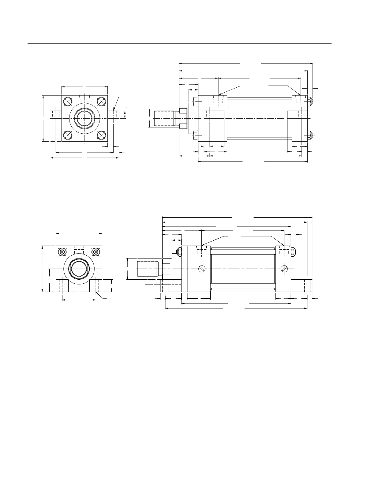
Mounting MS3, MS7
CDT1 MS3
ZB + STROKE
ZJ + STROKE
Y
E
1
SBØ
4 HOLES
W
V
P + STROKE
EE
K
E
CDT1 MS7
4
E
E
2
ST
4
3
TS
US
E
1
3
R
2
SW
2
ET
4 PLACES
SX
MM
ET
MM
SY
SU
G
F
XS
XE + STROKE
Y
W
V
G J EL EOEO
FEL
ZJ + STROKE
EE NPTF
LB + STROKE
SE + STROKE
SS + STROKE
LB + STROKE
P + STROKE
J
SY
SU
K
The side or lug mounted cylinder provides a fairly rigid mount.
These type mounts can tolerate a slight amount of misalignment when the cylinder is at full stroke, but as the piston
moves towards the blind end, the tolerance for misalignment
decreases. It is important to note that if the cylinder is used
properly, the mounting bolts are in simple shear or tension
without any compound stresses. An extended key plate option
is available to eliminate the ened for fitted bolts or external
keys to carry the thrust load (seep age 31)
When specifying an MS7 mount, carefully check the distance
between the rod and lug to determine if there is sufficient clearance for the rod end attachment. It may be necessary to add a
plain rod extension to move the threaded rod end out beyond
the lug. The lugs serve as nuts on the bottom two tie rods,
therefore making it necessary to loosen the tie rods to remove
the rod bearing.
Rod end options shown on page 6.
Page 17

RA 17038/02.13 | CDT1/CGT1 Industrial Hydraulics | Bosch Rexroth Corp. 17/44
Dimensions MS3, MS7
Table 1 - Dimensions affected by rod diameter
Bore MM
In. Rod V W Y XE XS ZB ZJ ZE
1.500 0.625 0.25 0.63 1.94 5.38 1.38 4.88 4.63 5.63
1.000 0.50 1.00 2.31 5.75 1.75 5.25 5.00 6.00
2.000 0.625 0.25 0.63 1.94 5.56 1.38 4.94 4.63 5.88
1.000 0.50 1.00 2.31 5.94 1.75 5.31 5.00 6.25
1.375 0.63 1.25 2.56 6.19 2.00 5.56 5.25 6.50
2.500 0.625 0.25 0.63 1.94 5.81 1.38 5.06 4.75 6.13
1.000 0.50 1.00 2.31 6.19 1.75 5.44 5.13 6.50
1.375 0.63 1.25 2.56 6.44 2.00 5.69 5.38 6.75
1.750 0.75 1.50 2.81 6.69 2.25 5.94 5.63 7.00
3.250 1.000 0.25 0.75 2.38 6.50 1.88 6.00 5.63 6.88
1.375 0.38 1.00 2.63 6.75 2.13 6.25 5.88 7.13
1.750 0.50 1.25 2.88 7.00 2.38 6.50 6.13 7.38
2.000 0.50 1.38 3.00 7.13 2.50 6.63 6.25 7.50
4.000 1.000 0.25 0.75 2.38 6.63 1.88 6.00 5.63 7.00
1.375 0.38 1.00 2.63 6.88 2.13 6.25 5.88 7.25
1.750 0.50 1.25 2.88 7.13 2.38 6.50 6.13 7.50
2.000 0.50 1.38 3.00 7.25 2.50 6.63 6.25 7.63
2.500 0.63 1.63 3.25 7.50 2.75 6.88 6.50 7.88
5.000 1.000 0.25 0.75 2.38 6.94 2.06 6.31 5.88 7.43
1.375 0.38 1.00 2.63 7.19 2.31 6.56 6.13 7.69
1.750 0.50 1.25 2.88 7.44 2.56 6.87 6.38 7.94
2.000 0.50 1.38 3.00 7.56 2.69 6.94 6.50 8.06
2.500 0.63 1.63 3.25 7.81 2.94 7.19 6.75 8.31
3.000 0.63 1.63 3.25 7.81 2.94 7.19 6.75 8.31
3.500 0.63 1.63 3.25 7.81 2.94 7.19 6.75 8.31
6.000 1.375 0.25 0.88 2.78 7.63 2.31 7.06 6.63 8.13
1.750 0.38 1.13 3.03 7.88 2.56 7.31 6.88 8.38
2.000 0.38 1.25 3.16 8.00 2.69 7.44 7.00 8.50
2.500 0.50 1.50 3.41 8.25 2.94 7.69 7.25 8.75
3.000 0.50 1.50 3.41 8.25 2.94 7.69 7.25 8.75
3.500 0.50 1.50 3.41 8.25 2.94 7.69 7.25 8.75
4.000 0.50 1.50 3.41 8.25 2.94 7.69 7.25 8.75
8.000 1.375 0.25 0.88 2.78 7.88 2.69 7.31 6.75 8.25
1.750 0.38 1.13 3.03 8.13 2.94 7.56 7.00 8.75
2.000 0.38 1.25 3.16 8.25 2.94 7.69 7.13 8.88
2.500 0.50 1.50 3.41 8.50 2.94 7.94 7.38 9.13
3.000 0.50 1.50 3.41 # 2.94 7.94 7.38 #
3.500 0.50 1.50 3.41 # 2.94 7.94 7.38 #
4.000 0.50 1.50 3.41 # 2.31 7.94 7.38 #
4.500 0.50 1.50 3.41 # 2.56 7.94 7.38 #
5.000 0.50 1.50 3.41 # 2.94 7.94 7.38 #
5.500 0.50 1.50 3.41 # 2.94 7.94 7.38 #
# = MS7 not available in this rod size
Table 2 - Dimensions not affected by rod diameter
Bore SAE NPT
in. E EB EE EE EL EO ET F G J K R SB S SS ST SU SW SX SY TS US LB P SE
1.500 2.00 0.38 -6 3/8 0.75 0.25 0.53 0.38 1.50 1.00 0.25 1.43 0.44 5.50 2.88 0.50 0.94 0.38 0.31 0.31 2.75 3.50 4.00 2.28 5.50
2.000 2.50 0.38 -6 3/8 0.94 0.31 0.63 0.38 1.50 1.00 0.31 1.84 0.44 5.88 2.88 0.50 0.94 0.38 0.38 0.38 3.25 4.00 4.00 2.28 5.88
2.500 3.00 0.38 -6 3/8 1.06 0.31 0.78 0.38 1.50 1.00 0.31 2.19 0.44 6.25 3.00 0.50 0.94 0.38 0.50 0.38 3.75 4.50 4.13 2.38 6.25
3.250 3.75 0.50 -10 1/2 0.88 0.38 0.94 0.63 1.75 1.25 0.38 2.76 0.56 6.63 3.25 0.75 1.25 0.50 0.50 0.50 4.75 5.75 4.88 2.69 6.63
4.000 4.50 0.50 -10 1/2 1.00 0.38 1.16 0.63 1.75 1.25 0.38 3.32 0.56 6.88 3.25 0.75 1.25 0.50 0.50 0.50 5.50 6.50 4.88 2.69 6.88
5.000 5.50 0.50 -10 1/2 1.06 0.50 1.38 0.63 1.75 1.25 0.44 4.10 0.81 7.25 3.13 1.00 1.56 0.69 0.69 0.69 6.88 8.25 5.13 2.94 7.25
6.000 6.50 0.75 -12 3/4 1.00 0.50 1.59 0.75 2.00 1.50 0.44 4.88 0.81 7.75 3.63 1.00 1.56 0.69 0.69 0.69 7.88 9.25 5.75 3.16 7.75
8.000 8.50 0.69 -12 3/4 1.13 0.63 1.94 0.75 2.00 1.50 0.56 6.44 0.81 7.38 3.75 1.00 1.56 0.69 0.88 0.69 9.88 11.25 5.88 3.28 7.38
Page 18
18/44 Bosch Rexroth Corp. | Industrial Hydraulics CDT1/CGT1 | RA 17038/02.13
XG
ZJ + STROKE
K
ZJ + STROKE
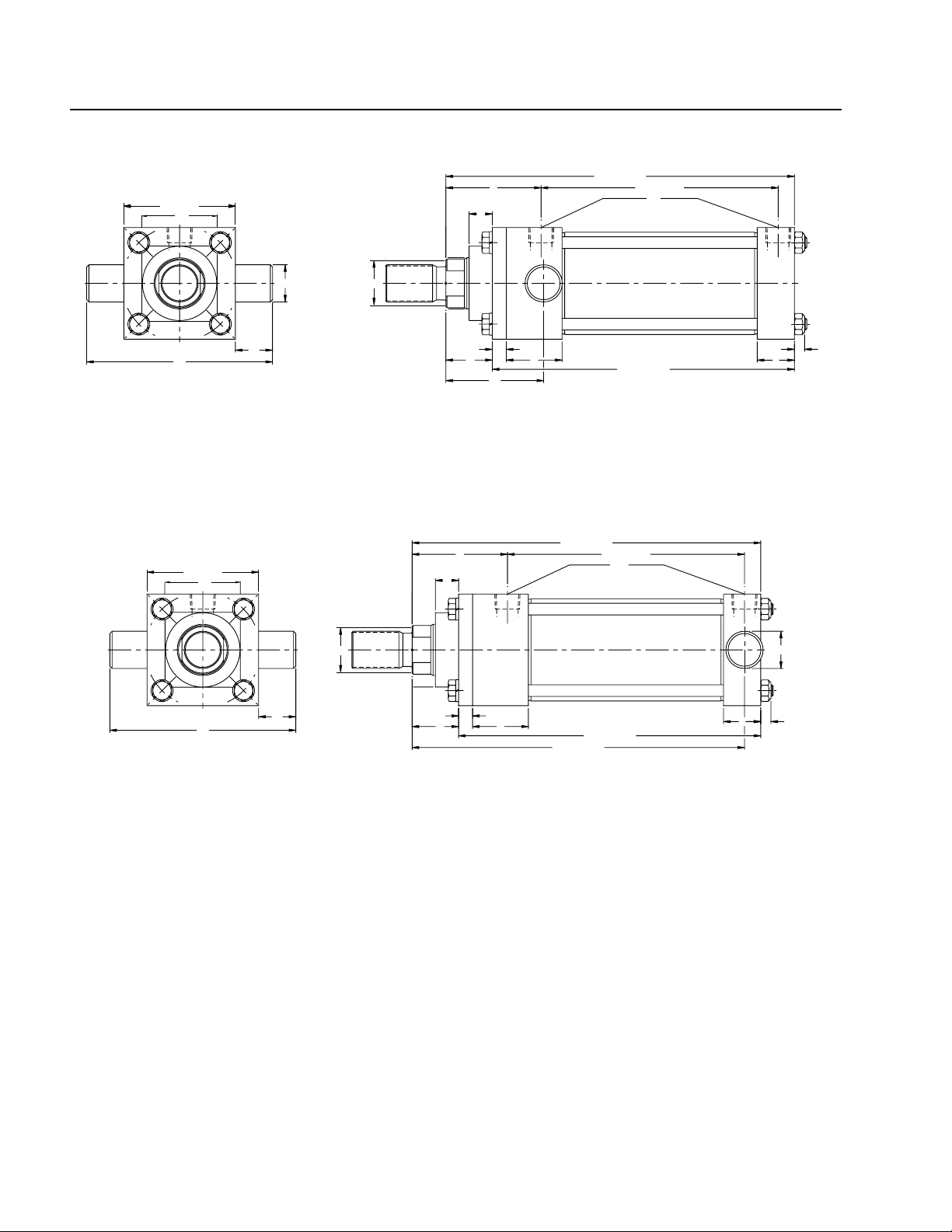
Mounting MT1, MT2
CDT1 MT1
P + STROKEY
E SQUARE
XN
1
+.000
4
2
Ø TD
-.001
MM
V
EE
CDT1 MT2
3
UT
E SQUARE
XN
4
3
UT
TL
1
2
TL
MM
W
Y
V
W
F
G
F
G
XJ + STROKE
P + STROKE
EE
LB + STROKE
LB + STROKE
J
Ø TD
+.000
-.001
KJ
Page 19

RA 17038/02.13 | CDT1/CGT1 Industrial Hydraulics | Bosch Rexroth Corp. 19/44
Dimensions MT1, MT2
Table 1 - Dimensions affected by rod diameter
Bore Rod
In. mm V W Y XG XJ XN ZJ
1.500 0.625 0.25 0.63 1.94 1.75 4.13 - 4.63
1.000 0.50 1.00 2.31 2.13 4.50 - 5.00
2.000 0.625 0.25 0.63 1.94 1.75 4.13 - 4.63
1.000 0.50 1.00 2.31 2.13 4.50 - 5.00
1.375 0.63 1.25 2.56 2.38 4.75 - 5.25
2.500 0.625 0.25 0.63 1.94 1.75 4.25 - 4.75
1.000 0.50 1.00 2.31 2.13 4.63 - 5.13
1.375 0.63 1.25 2.56 2.38 4.88 - 5.38
1.750 0.75 1.50 2.81 2.63 5.13 - 5.63
3.250 1.000 0.25 0.75 2.38 2.25 5.00 - 5.63
1.375 0.38 1.00 2.63 2.50 5.25 - 5.88
1.750 0.50 1.25 2.88 2.75 5.50 - 6.13
2.000 0.50 1.38 3.00 2.88 5.63 - 6.25
4.000 1.000 0.25 0.75 2.38 2.25 5.00 - 5.63
1.375 0.38 1.00 2.63 2.50 5.25 - 5.88
1.750 0.50 1.25 2.88 2.75 5.50 - 6.13
2.000 0.50 1.38 3.00 2.88 5.63 - 6.25
2.500 0.63 1.63 3.25 3.13 5.88 - 6.50
5.000 1.000 0.25 0.75 2.38 2.25 5.25 - 5.88
1.375 0.38 1.00 2.63 2.50 5.50 - 6.13
1.750 0.50 1.25 2.88 2.75 5.75 - 6.38
2.000 0.50 1.38 3.00 2.88 5.88 - 6.50
2.500 0.63 1.63 3.25 3.13 6.13 - 6.75
3.000 0.63 1.63 3.25 3.13 6.13 - 6.75
3.500 0.63 1.63 3.25 3.13 6.13 - 6.75
6.000 1.375 0.25 0.88 2.78 2.63 5.88 - 6.63
1.750 0.38 1.13 3.03 2.88 6.13 - 6.88
2.000 0.38 1.25 3.16 3.00 6.25 - 7.00
2.500 0.50 1.50 3.41 3.25 6.50 - 7.25
3.000 0.50 1.50 3.41 3.25 6.50 - 7.25
3.500 0.50 1.50 3.41 3.25 6.50 - 7.25
4.000 0.50 1.50 3.41 3.25 6.50 - 7.25
8.000 1.375 0.25 0.88 2.78 2.63 6.00 4.00 6.75
1.750 0.38 1.13 3.03 2.88 6.25 4.00 7.00
2.000 0.38 1.25 3.16 3.00 6.38 4.00 7.13
2.500 0.50 1.50 3.41 3.25 6.63 4.00 7.38
3.000 0.50 1.50 3.41 3.25 6.63 5.50 7.38
3.500 0.50 1.50 3.41 3.25 6.63 5.50 7.38
4.000 0.50 1.50 3.41 3.25 6.63 5.50 7.38
4.500 0.50 1.50 3.41 3.25 6.63 6.50 7.38
5.000 0.50 1.50 3.41 3.25 6.63 6.50 7.38
5.500 0.50 1.50 3.41 3.25 6.63 7.25 7.38
All trunnion mount cylinders need a provision
on both ends for pivoting. These types of
cylinders are designed to carry shear loads and
the trunnion and pivot pins should be carried by
bearings that are rigidly held and closely fit for
the entire length of the pin.
Head or rod end trunnions should be carefully
applied to either short strokes or to applications
where the weight of the cylinder falls vertically
below the pin.
NOTE: The “XG” and “XJ” dimensions for MT1
and MT2 mounts are not NFPA Standard.
NOTE: The bearing retainer plate is the same
as the “E” dimension for the 1.5” – 6” bore
sizes and the “XN” dimension for the 8” bore
size.
Rod end options shown on page 6.
Table 2 - Dimensions not affected by rod diameter
TD
Bore SAE Port NPT Port +.000
In. E EE EE F G J K -.001* TL UT UB P LB
1.500 2.00 -6 3/8 0.38 1.50 1.00 0.25 1.000 1.00 4.00 4.00 2.28 4.00
2.000 2.50 -6 3/8 0.38 1.50 1.00 0.31 1.000 1.00 4.50 4.00 2.28 4.00
2.500 3.00 -6 3/8 0.38 1.50 1.00 0.31 1.000 1.00 5.00 4.13 2.38 4.13
3.250 3.75 -10 1/2 0.63 1.75 1.25 0.38 1.000 1.00 5.75 4.88 2.69 4.88
4.000 4.50 -10 1/2 0.63 1.75 1.25 0.38 1.000 1.00 6.50 4.88 2.69 4.88
5.000 5.50 -10 1/2 0.63 1.75 1.25 0.44 1.000 1.00 7.50 5.13 2.94 5.13
6.000 6.50 -12 3/4 0.75 2.00 1.50 0.44 1.375 1.38 9.25 5.75 3.16 5.75
8.000 8.50 -12 3/4 0.75 2.00 1.50 0.56 1.375 1.38 11.25 5.88 3.28 5.88
Page 20
20/44 Bosch Rexroth Corp. | Industrial Hydraulics CDT1/CGT1 | RA 17038/02.13
EE
BD
+.000
-.001
TD
UM
TM
TL
UV
XV
K
ZJ + STROKE
Y
P + STROKE
F
LB + STROKE
V
J
G
W
E
4
3
2
1
XN
MM
E
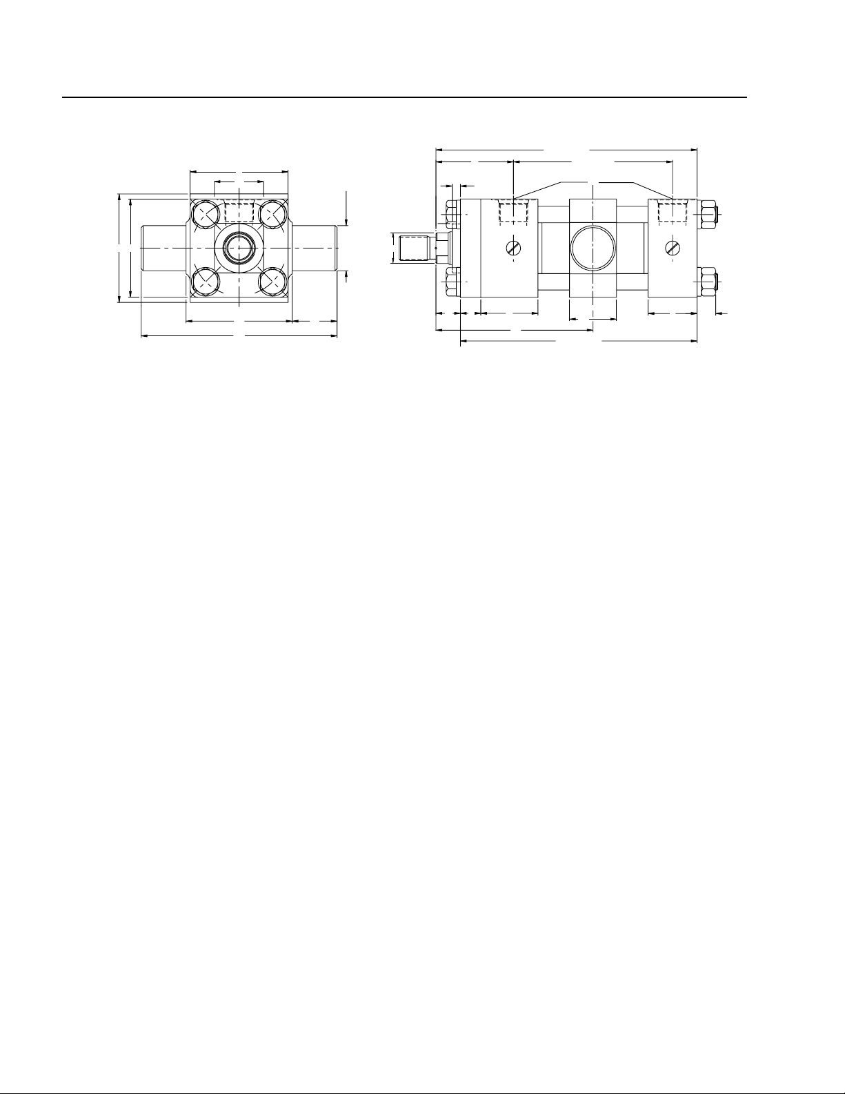
Mounting MT4
CDT1 MT4
All trunnion mounted cylinders need a provision on both ends
for pivoting. These types of cylinders are designed to carry
shear loads and the trunnion and pivot pins should be carried
by bearings that are rigidly held and closely fit for the entire
length of the pin.
Specify “XV” dimension when ordering MT4 Intermediate Fixed
Trunnnion mounts. If not specified, trunnion will be located at
the center of the tube.
NOTE: The bearing retainer plate is the same as the “E” dimension for the 1.5” – 6” bore sizes and the “XN” dimension for the
8” bore size.
Rod end options shown on page 6.
Page 21
RA 17038/02.13 | CDT1/CGT1 Industrial Hydraulics | Bosch Rexroth Corp. 21/44
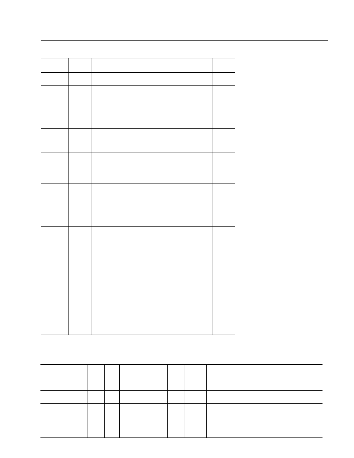
Dimensions MT4
Table 1 - Dimensions affected by rod diameter
Bore MM XV
In. Rod V W Y Min. ZJ XN
1.500 0.625 0.25 0.63 1.94 3.19 4.63 -
1.000 0.50 1.00 2.31 3.56 5.00 -
2.000 0.625 0.25 0.63 1.94 3.31 4.63 -
1.000 0.50 1.00 2.31 3.69 5.00 -
1.375 0.63 1.25 2.56 3.94 5.25 -
2.500 0.625 0.25 0.63 1.94 3.31 4.75 -
1.000 0.50 1.00 2.31 3.69 5.13 -
1.375 0.63 1.25 2.56 3.94 5.38 -
1.750 0.75 1.50 2.81 4.19 5.63 -
3.250 1.000 0.25 0.75 2.38 4.19 5.63 -
1.375 0.38 1.00 2.63 4.44 5.88 -
1.750 0.50 1.25 2.88 4.69 6.13 -
2.000 0.50 1.38 3.00 4.81 6.25 -
4.000 1.000 0.25 0.75 2.38 4.19 5.63 -
1.375 0.38 1.00 2.63 4.44 5.88 -
1.750 0.50 1.25 2.88 4.69 6.13 -
2.000 0.50 1.38 3.00 4.81 6.25 -
2.500 0.63 1.63 3.25 5.06 6.50 -
5.000 1.000 0.25 0.75 2.38 4.19 5.88 -
1.375 0.38 1.00 2.63 4.44 6.13 -
1.750 0.50 1.25 2.88 4.69 6.38 -
2.000 0.50 1.38 3.00 4.81 6.50 -
2.500 0.63 1.63 3.25 5.06 6.75 -
3.000 0.63 1.63 3.25 5.06 6.75 -
3.500 0.63 1.63 3.25 5.06 6.75 -
6.000 1.375 0.25 0.88 2.78 4.94 6.63 -
1.750 0.38 1.13 3.03 5.19 6.88 -
2.000 0.38 1.25 3.16 5.31 7.00 -
2.500 0.50 1.50 3.41 5.56 7.25 -
3.000 0.50 1.50 3.41 5.56 7.25 -
3.500 0.50 1.50 3.41 5.56 7.25 -
4.000 0.50 1.50 3.41 5.56 7.25 -
8.000 1.375 0.25 0.88 2.78 4.94 6.75 4.00
1.750 0.38 1.13 3.03 5.19 7.00 4.00
2.000 0.38 1.25 3.16 5.31 7.13 4.00
2.500 0.50 1.50 3.41 5.56 7.38 4.00
3.000 0.50 1.50 3.41 5.56 7.38 5.50
3.500 0.50 1.50 3.41 5.56 7.38 5.50
4.000 0.50 1.50 3.41 5.56 7.38 5.50
4.500 0.50 1.50 3.41 5.56 7.38 6.50
5.000 0.50 1.50 3.41 5.56 7.38 6.50
5.500 0.50 1.50 3.41 5.56 7.38 7.25
~ = Exact XV value to be specified by customer when ordering.
Table 2 - Dimensions not affected by rod diameter
Bore SAE NPT TD
Port Port +.000 Min.
In. BD E EE EE F G J K –.001* TL TM UM UV LB P Stroke
1.500 1.25 2.00 -6 3/8 0.38 1.50 1.00 0.25 1.000 1.00 2.50 4.50 2.50 4.00 2.28 0.25
2.000 1.50 2.50 -6 3/8 0.38 1.50 1.00 0.31 1.000 1.00 3.00 5.00 3.00 4.00 2.28 0.50
2.500 1.50 3.00 -6 3/8 0.38 1.50 1.00 0.31 1.000 1.00 3.50 5.50 3.50 4.13 2.38 0.38
3.250 2.00 3.75 -10 1/2 0.63 1.75 1.25 0.38 1.000 1.00 4.50 6.50 4.25 4.88 2.69 0.88
4.000 2.00 4.50 -10 1/2 0.63 1.75 1.25 0.38 1.000 1.00 5.25 7.25 5.00 4.88 2.69 0.88
5.000 2.00 5.50 -10 1/2 0.63 1.75 1.25 0.44 1.000 1.00 6.25 8.25 6.00 5.13 2.94 0.63
6.000 2.50 6.50 -12 3/4 0.75 2.00 1.50 0.44 1.375 1.38 7.63 10.38 7.38 5.75 3.16 1.13
8.000 2.50 8.50 -12 3/4 0.75 2.00 1.50 0.56 1.375 1.38 9.75 12.50 9.50 5.88 3.28 0.88
Page 22
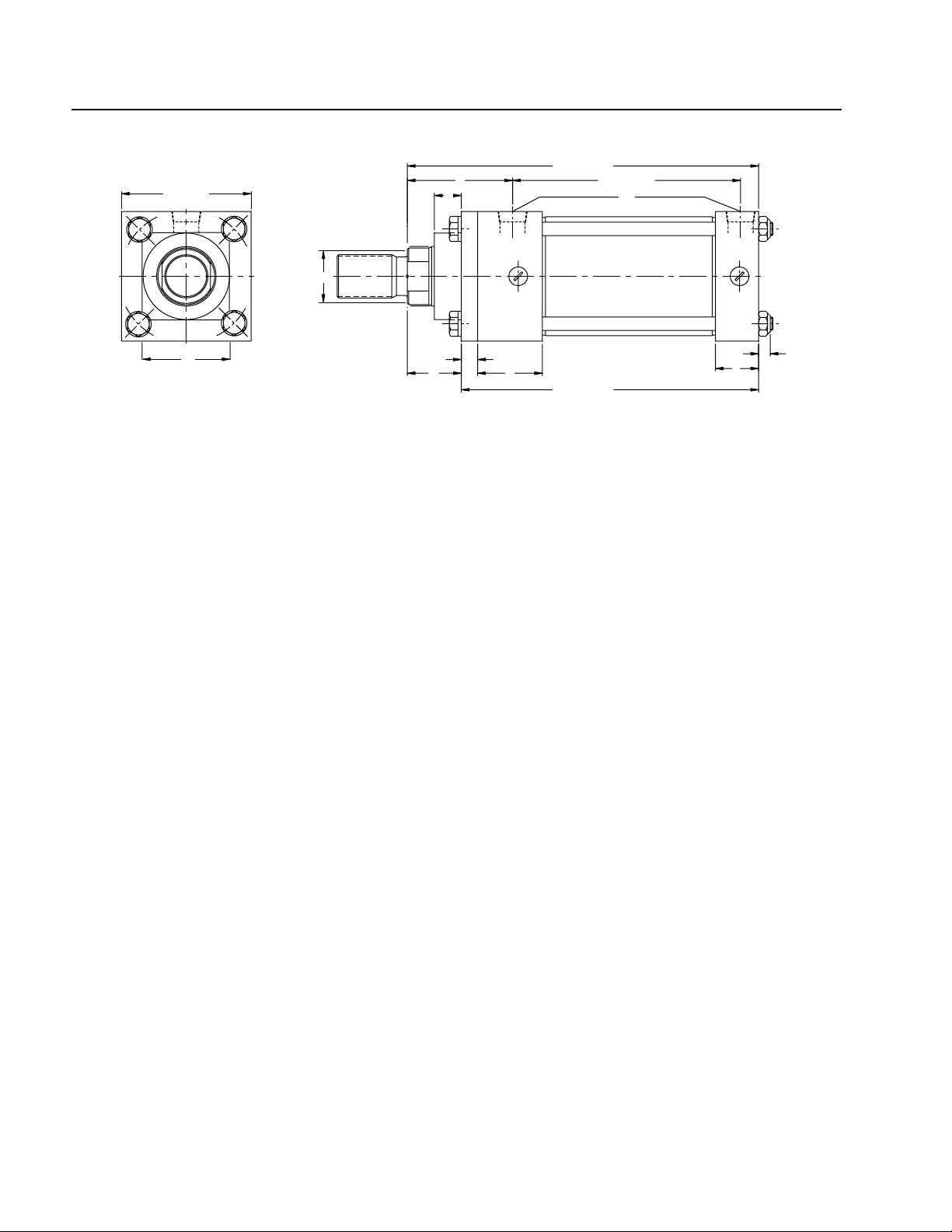
22/44 Bosch Rexroth Corp. | Industrial Hydraulics CDT1/CGT1 | RA 17038/02.13
LB + STROKE
ZJ + STROKE
4
Mounting MX0
CDT1 MX0
E SQUARE
1
3
XN
Y
V
2
MM
F
W
G
P + STROKE
EE
K
J
Page 23

RA 17038/02.13 | CDT1/CGT1 Industrial Hydraulics | Bosch Rexroth Corp. 23/44
Dimensions MX0
Table 1 - Dimensions affected by rod diameter
Bore Ø Rod Ø
In. In. V W Y ZJ XN
1.500 0.625 0.25 0.63 1.94 4.63 -
1.000 0.50 1.00 2.31 5.00 -
2.000 0.625 0.25 0.63 1.94 4.63 -
1.000 0.50 1.00 2.31 5.00 -
1.375 0.63 1.25 2.56 5.25 -
2.500 0.625 0.25 0.63 1.94 4.75 -
1.000 0.50 1.00 2.31 5.13 -
1.375 0.63 1.25 2.56 5.38 -
1.750 0.75 1.50 2.81 5.63 -
3.250 1.000 0.25 0.75 2.38 5.63 -
1.375 0.38 1.00 2.63 5.88 -
1.750 0.50 1.25 2.88 6.13 -
2.000 0.50 1.38 3.00 6.25 -
4.000 1.000 0.25 0.75 2.38 5.63 -
1.375 0.38 1.00 2.63 5.88 -
1.750 0.50 1.25 2.88 6.13 -
2.000 0.50 1.38 3.00 6.25 -
2.500 0.63 1.63 3.25 6.50 -
5.000 1.000 0.25 0.75 2.38 5.88 -
1.375 0.38 1.00 2.63 6.13 -
1.750 0.50 1.25 2.88 6.38 -
2.000 0.50 1.38 3.00 6.50 -
2.500 0.63 1.63 3.25 6.75 -
3.000 0.63 1.63 3.25 6.75 -
3.500 0.63 1.63 3.25 6.75 -
6.000 1.375 0.25 0.88 2.78 6.63 -
1.750 0.38 1.13 3.03 6.88 -
2.000 0.38 1.25 3.16 7.00 -
2.500 0.50 1.50 3.41 7.25 -
3.000 0.50 1.50 3.41 7.25 -
3.500 0.50 1.50 3.41 7.25 -
4.000 0.50 1.50 3.41 7.25 -
8.000 1.375 0.25 0.88 2.78 6.75 4.00
1.750 0.38 1.13 3.03 7.00 4.00
2.000 0.38 1.25 3.16 7.13 4.00
2.500 0.50 1.50 3.41 7.38 4.00
3.000 0.50 1.50 3.41 7.38 5.50
3.500 0.50 1.50 3.41 7.38 5.50
4.000 0.50 1.50 3.41 7.38 5.50
4.500 0.50 1.50 3.41 7.38 7.00
5.000 0.50 1.50 3.41 7.38 7.00
5.500 0.50 1.50 3.41 7.38 7.00
Rod end options shown on page 6.
Table 2 - Dimensions not affected by rod diameter
Bore SAE Port NPT Port
In. E EE EE F G J K LB P
1.500 2.00 -6 3/8 0.38 1.50 1.00 0.25 4.00 2.28
2.000 2.50 -6 3/8 0.38 1.50 1.00 0.31 4.00 2.28
2.500 3.00 -6 3/8 0.38 1.50 1.00 0.31 4.13 2.38
3.250 3.75 -10 1/2 0.63 1.75 1.25 0.38 4.88 2.69
4.000 4.50 -10 1/2 0.63 1.75 1.25 0.38 4.88 2.69
5.000 5.50 -10 1/2 0.63 1.75 1.25 0.44 5.13 2.94
6.000 6.50 -12 3/4 0.75 2.00 1.50 0.44 5.75 3.16
8.000 8.50 -12 3/4 0.75 2.00 1.50 0.56 5.88 3.28
Page 24
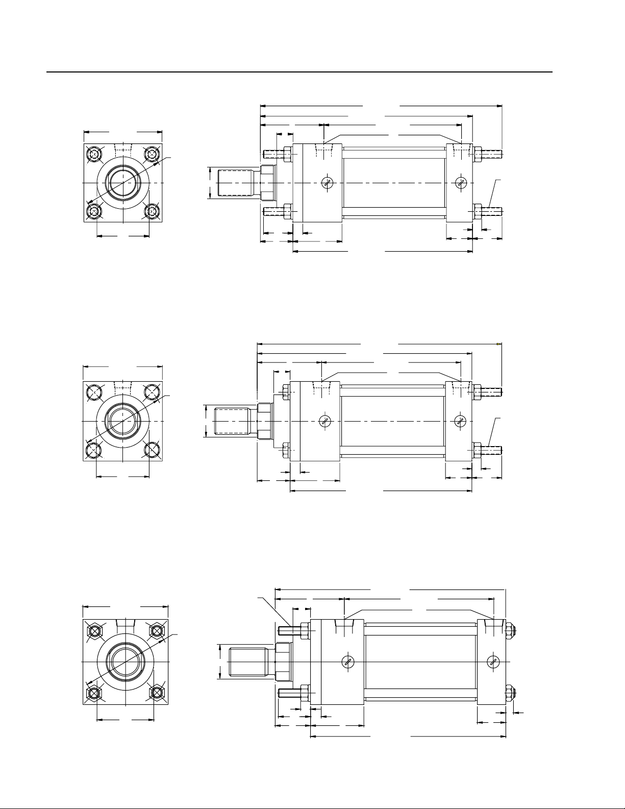
24/44 Bosch Rexroth Corp. | Industrial Hydraulics CDT1/CGT1 | RA 17038/02.13
ZT + STROKE
DD THD.
EE
ZT + STROKE
Ø AA
BB
-.003
+.000
Ø B
K
J
LB + STROKE
G
F
W
ZJ + STROKE
P + STROKEY
V
E SQUARE
3
4
2
1
MM
ZJ + STROKE
4
Mounting MX1, MX2, MX3
CDT1 MX1
4
CDT1 MX2
E SQUARE
1
3
+.000
-.003
Ø B
Y
V
ØAA
2
MM
BB
W
F
G
ZJ + STROKE
LB + STROKE
P + STROKE
EE
DD THD.
K
BB
J
CDT1 MX3
MM
DD THD.
E SQUARE
1
Ø AA
2
3
Ø B
+.000
-.003
V
K
BB
W
Y
F
G
LB + STROKE
P + STROKE
EE
K
J
Page 25

RA 17038/02.13 | CDT1/CGT1 Industrial Hydraulics | Bosch Rexroth Corp. 25/44
Dimensions MX1, MX2, MX3
Table 1 - Dimensions affected by rod diameter
Bore Rod
In. In. V W Y ZJ ZT
1.500 0.625 0.25 0.63 1.94 4.63 5.62
1.000 0.50 1.00 2.31 5.00 6.00
2.000 0.625 0.25 0.63 1.94 4.63 5.75
1.000 0.50 1.00 2.31 5.00 6.12
1.375 0.63 1.25 2.56 5.25 6.38
2.500 0.625 0.25 0.63 1.94 4.75 5.88
1.000 0.50 1.00 2.31 5.13 6.25
1.375 0.63 1.25 2.56 5.38 6.50
1.750 0.75 1.50 2.81 5.63 6.75
3.250 1.000 0.25 0.75 2.38 5.63 7.00
1.375 0.38 1.00 2.63 5.88 7.25
1.750 0.50 1.25 2.88 6.13 7.50
2.000 0.50 1.38 3.00 6.25 7.62
4.000 1.000 0.25 0.75 2.38 5.63 7.00
1.375 0.38 1.00 2.63 5.88 7.25
1.750 0.50 1.25 2.88 6.13 7.50
2.000 0.50 1.38 3.00 6.25 7.62
2.500 0.63 1.63 3.25 6.50 7.88
5.000 1.000 0.25 0.75 2.38 5.88 7.69
1.375 0.38 1.00 2.63 6.13 7.94
1.750 0.50 1.25 2.88 6.38 8.19
2.000 0.50 1.38 3.00 6.50 8.31
2.500 0.63 1.63 3.25 6.75 8.56
3.000 0.63 1.63 3.25 6.75 8.56
3.500 0.63 1.63 3.25 6.75 8.56
6.000 1.375 0.25 0.88 2.78 6.63 8.44
1.750 0.38 1.13 3.03 6.88 8.69
2.000 0.38 1.25 3.16 7.00 8.81
2.500 0.50 1.50 3.41 7.25 9.06
3.000 0.50 1.50 3.41 7.25 9.06
3.500 0.50 1.50 3.41 7.25 9.06
4.000 0.50 1.50 3.41 7.25 9.06
Tie Rod and Flange Mounts are basically the
same except that the tie rods are extended and
used to mount the cylinder. To prevent misalignment, sagging or binding of the cylinder when
long strokes are required, the free end of the
cylinder should be supported. For thrust load
applications, blind or cap end tie rod extensions
are best. For tension load applications, rod or
head end extensions are best. Tie rod mounts are
suited form any applications, however it should
be noted that they are not as rigid as the flange
mountings.
NOTE: The bearing retainer plate is the same as
the “E” dimension for the 1.5” – 6” bore sizes.
Rod end options shown on page 6.
Table 2 - Dimensions not affected by rod diameter
Bore SAE Port NPT Port
In. E EE EE F G J K AA BB DD LB P
1.500 2.00 -6 3/8 0.38 1.50 1.00 0.25 2.02 1.00 1/4 - 28 4.00 2.2
2.000 2.50 -6 3/8 0.38 1.50 1.00 0.31 2.60 1.13 5/16 - 24 4.00 2.28
2.500 3.00 -6 3/8 0.38 1.50 1.00 0.31 3.10 1.13 5/16 - 24 4.13 2.38
3.250 3.75 -10 1/2 0.63 1.75 1.25 0.38 3.90 1.38 3/8 - 24 4.88 2.69
4.000 4.50 -10 1/2 0.63 1.75 1.25 0.38 4.70 1.38 3/8 - 24 4.88 2.6
5.000 5.50 -10 1/2 0.63 1.75 1.25 0.44 5.80 1.81 1/2 - 20 5.13 2.9
6.000 6.50 -12 3/4 0.75 2.00 1.50 0.44 6.90 1.81 1/2 - 20 5.75 3.16
Page 26
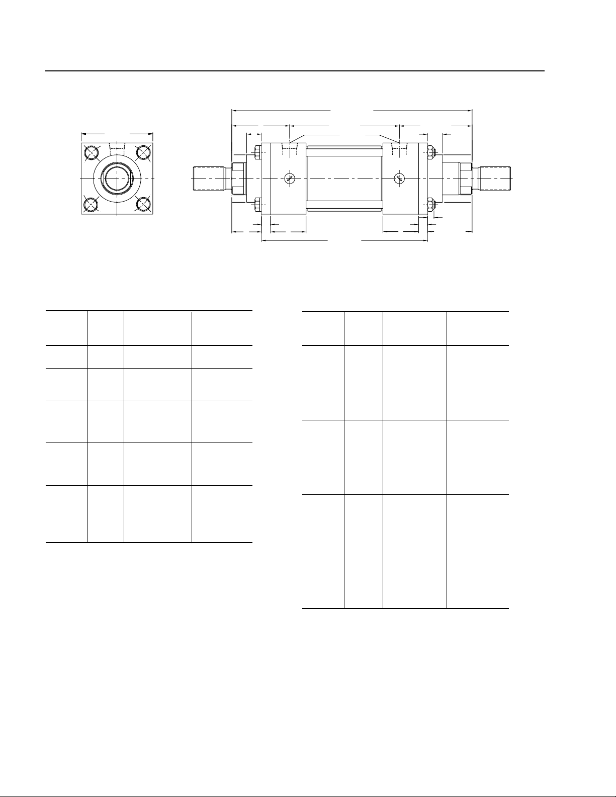
26/44 Bosch Rexroth Corp. | Industrial Hydraulics CDT1/CGT1 | RA 17038/02.13
LD + STROKE
ZM + 2X STROKE
Mounting CGT1
CGT1
E SQUARE
1
4
3
2
Pressure Ratings for Double Rod End
Cushion Rod Cushion
Bore Rod end or Both Ends
Size Size Non-Cushion or Ext. (psi)
1.500 0.625 1,000 750
1.000 1,000 1,000
2.000 0.625 800 450
1.000 1,000 500
1.375 1,000 1,000
2.500 0.625 500 250
1.000 1,000 500
1.375 1,000 1,000
1.750 1,000 1,000
3.250 1.000 500 n/a
1.375 1,000 1,000
1.750 1,000 1,000
2.000 1,000 1,000
4.000 1.000 400 n/a
1.375 1,000 1,000
1.750 1,000 1,000
2.000 1,000 1,000
2.500 1,000 1,000
Y
V
F
W
G
P + STROKE
EE (NPTF)
Y + STROKE
V
K
G
F
W + STROKE
Cushion Rod Cushion
Bore Rod end or Both Ends
Size Size Non-Cushion or Ext. (psi)
5.000 1.000 250 n/a
1.375 750 750
1.750 750 750
2.000 750 750
2.500 750 750
3.000 750 750
3.500 750 750
6.000 1.375 250 n/a
1.750 750 750
2.000 750 750
2.500 675 675
3.000 750 750
3.500 750 750
4.000 750 750
8.000 1.375 200 n/a
1.750 500 450
2.000 500 500
2.500 500 500
3.000 500 500
3.500 500 500
4.000 500 500
4.500 500 500
5.000 500 500
5.500 500 500
Page 27

RA 17038/02.13 | CDT1/CGT1 Industrial Hydraulics | Bosch Rexroth Corp. 27/44
Mounting CGT1
Table 1 - Dimensions affected by rod diameter
Bore Rod
In. In. V W Y ZL ZM
1.500 0.625 0.25 0.63 1.94 5.73 6.13
1.000 0.50 1.00 2.31 6.10 6.88
2.000 0.625 0.25 0.63 1.94 5.78 6.13
1.000 0.50 1.00 2.31 6.15 6.88
1.375 0.63 1.25 2.56 6.40 7.38
2.500 0.625 0.25 0.63 1.94 5.90 6.25
1.000 0.50 1.00 2.31 6.27 7.00
1.375 0.63 1.25 2.56 6.52 7.50
1.750 0.75 1.50 2.81 6.77 8.00
3.250 1.000 0.25 0.75 2.38 7.09 7.50
1.375 0.38 1.00 2.63 7.34 8.00
1.750 0.50 1.25 2.88 7.59 8.50
2.000 0.50 1.38 3.00 7.72 8.75
4.000 1.000 0.25 0.75 2.38 7.09 7.50
1.375 0.38 1.00 2.63 7.34 8.00
1.750 0.50 1.25 2.88 7.59 8.50
2.000 0.50 1.38 3.00 7.72 8.75
2.500 0.63 1.63 3.25 7.97 9.25
5.000 1.000 0.25 0.75 2.38 7.44 7.75
1.375 0.38 1.00 2.63 7.69 8.25
1.750 0.50 1.25 2.88 7.94 8.75
2.000 0.50 1.38 3.00 8.07 9.00
2.500 0.63 1.63 3.25 8.32 9.50
3.000 0.63 1.63 3.25 8.32 9.50
3.500 0.63 1.63 3.25 8.32 9.50
6.000 1.375 0.25 0.88 2.78 8.32 8.75
1.750 0.38 1.13 3.03 8.57 9.25
2.000 0.38 1.25 3.16 8.69 9.50
2.500 0.50 1.50 3.41 8.94 10.00
3.000 0.50 1.50 3.41 8.94 10.00
3.500 0.50 1.50 3.41 8.94 10.00
4.000 0.50 1.50 3.41 8.94 10.00
8.000 1.375 0.25 0.88 2.78 7.82 8.88
1.750 0.38 1.13 3.03 8.07 9.38
2.000 0.38 1.25 3.16 8.19 9.63
2.500 0.50 1.50 3.41 8.44 10.13
3.000 0.50 1.50 3.41 8.44 10.13
3.500 0.50 1.50 3.41 8.44 10.13
4.000 0.50 1.50 3.41 8.44 10.13
4.500 0.50 1.50 3.41 8.44 10.13
5.000 0.50 1.50 3.41 8.44 10.13
5.500 0.50 1.50 3.41 8.44 10.13
Double rod end cylinders are available in every mounting
style except MP1, MP3 and MP5. For dimensions on
specific mounting styles, consult the page showing the
required mounting. On cylinders where the rod ends are
not the same, be sure to specify where each rod end is
located in relation to the mounting requirements.
Note that bore sizes 1-1/2” – 6” have square retainers,
the same square size as the head on both ends. One of
these retainers is held in place by the tie rod nuts, and
therefore cannot be removed without loosening the tie
rods.
Rod end options shown on page 6.
Consult factory for minimum stroke lenths.
Table 2 - Dimensions not affected by rod diameter
Bore SAE Port NPT Port
In. E EE EE F G K LD LB P
1.500 2.00 -6 3/8 0.38 1.50 0.25 4.88 4.00 2.25
2.000 2.50 -6 3/8 0.38 1.50 0.31 4.88 4.00 2.25
2.500 3.00 -6 3/8 0.38 1.50 0.31 5.00 4.13 2.38
3.250 3.75 -10 1/2 0.63 1.75 0.38 6.00 4.88 2.75
4.000 4.50 -10 1/2 0.63 1.75 0.38 6.00 4.88 2.69
5.000 5.50 -10 1/2 0.63 1.75 0.44 6.25 5.13 2.94
6.000 6.50 -12 3/4 0.75 2.00 0.44 7.00 5.75 3.16
8.000 8.50 -12 3/4 0.75 2.00 0.56 5.63 5.88 3.28
Page 28
28/44 Bosch Rexroth Corp. | Industrial Hydraulics CDT1/CGT1 | RA 17038/02.13
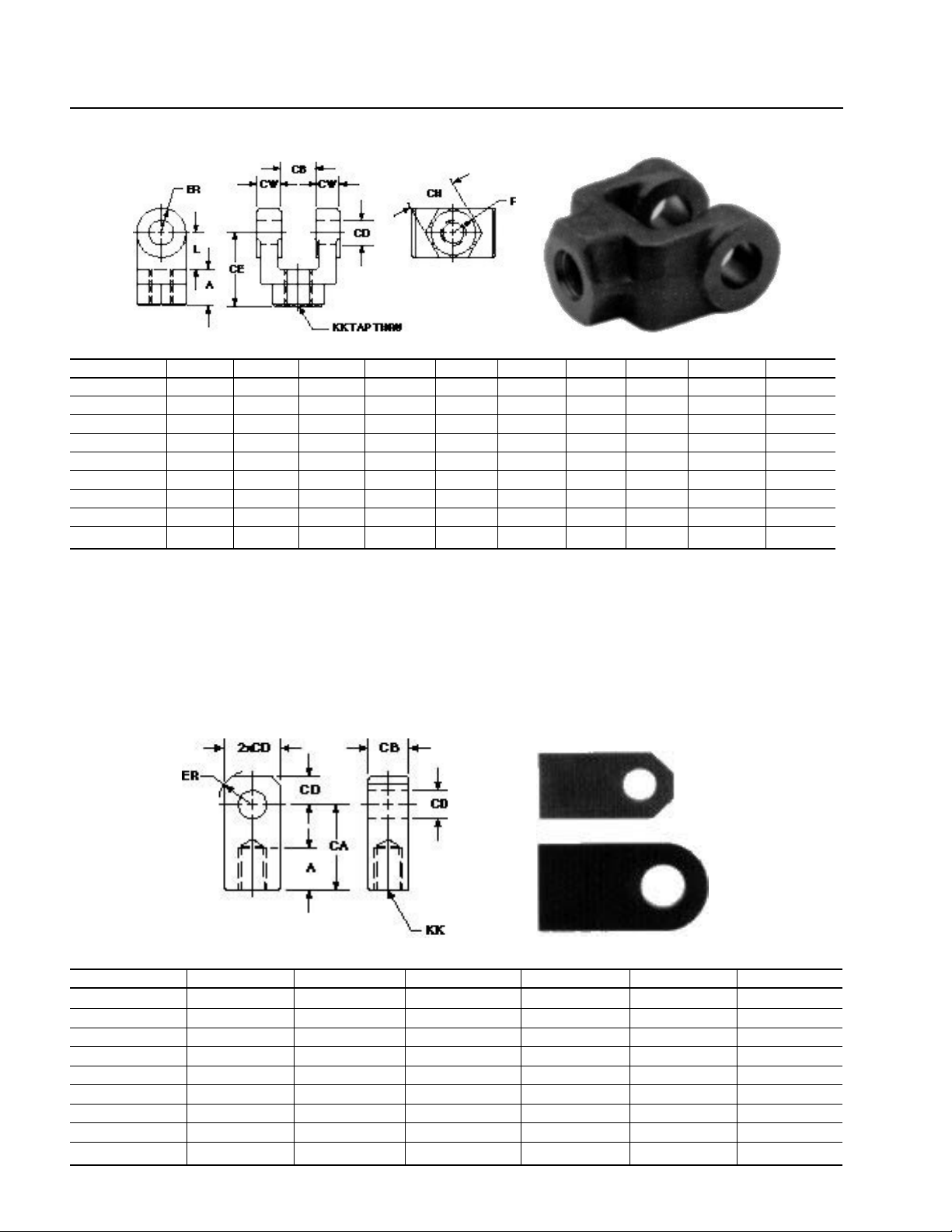
Rexroth Cylinder Accessories
Rod Clevises
Part No. CB CD CE CH CW F L A KK ER
R978935057 .765 0.50 1.50 1.00 0.50 1.00 0.75 0.75 7/16-20 0.50
R978935058 1.265 0.75 2.38 1.25 0.63 1.25 1.25 1.13 3/4-16 0.75
R978935059 1.265 0.75 2.17 1.38 0.63 1.25 1.00 1.13 3/4-16 0.75
R978935060 1.515 1.00 3.13 1.50 0.75 1.50 1.50 1.83 1-14 1.00
R978935061 2.032 1.38 4.13 2.00 1.00 2.00 2.13 2.00 1-1/4-12 1.38
R978935062 2.531 1.75 4.50 2.38 1.25 2.38 2.25 2.25 1-1/2-12 1.75
R978935063 2.531 2.00 5.50 2.94 1.25 2.94 2.50 3.00 1-7/8-12 2.00
R978935064 3.032 2.50 6.50 3.50 1.50 3.50 3.00 3.50 2-1/4-12 2.50
R978935065 3.032 3.00 6.75 3.88 1.50 3.88 3.25 3.50 2-1/2-12 2.75
Note: Pins must be ordered separately, see Page 31 for dimensions and part numbers.
Rod Eyes
Part No. A CA CB CD ER KK
R978935066 0.75 1.50 0.75 0.50 0.63 7/16-20
R978935067 1.13 2.06 1.25 0.75 0.88 3/4-16
R978935068 1.13 2.81 1.50 1.00 1.19 1-14
R978935069 1.83 2.38 1.50 1.00 1.44 7/8-14
R978935070 2.00 3.44 2.00 1.38 1.56 1-1/4-12
R978935071 2.25 4.00 2.50 1.75 2.00 1-1/2-12
R978935072 3.00 5.00 2.50 2.00 2.50 1-7/8-12
R978935073 3.50 5.81 3.00 2.50 2.81 2-1/4-12
R978935074 3.50 6.13 3.00 3.00 3.25 2-1/2-12
Page 29
RA 17038/02.13 | CDT1/CGT1 Industrial Hydraulics | Bosch Rexroth Corp. 29/44
Rexroth Cylinder Accessories
Spherical Rod Eyes
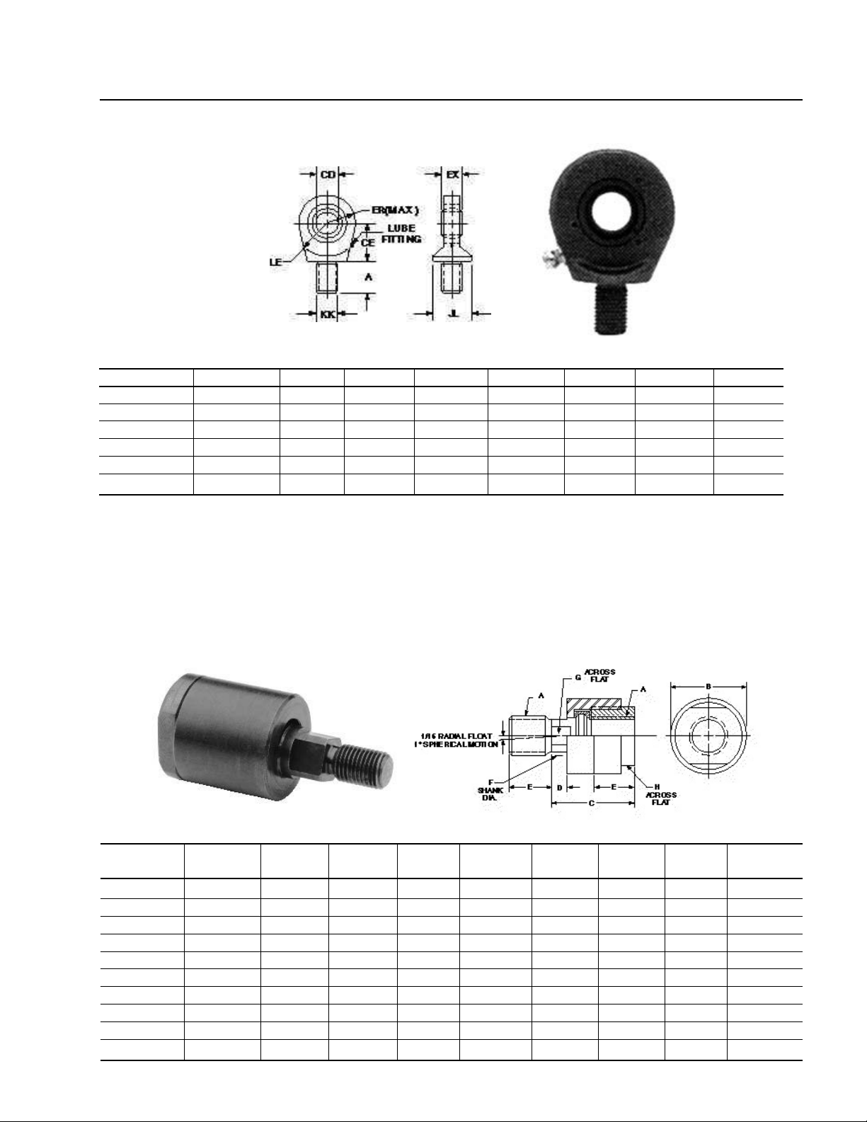
Part No. CD -.0005 A CE EX ER LE KK JL
R978935075 0.500 1.06 0.88 0.44 0.88 0.75 7/16-20 0.88
R978935076 0.750 1.00 1.25 2.03 1.25 1.06 3/4-16 1.31
R978935077 1.000 1.50 1.88 0.88 1.38 1.44 1-14 1.50
R978935078 1.375 2.00 2.13 1.19 1.81 1.88 1-1/4-12 2.00
R978935079 1.750 2.13 2.50 1.53 2.19 2.13 1-1/2-12 2.25
R978935081 2.000 2.88 2.75 1.75 2.63 2.50 1-7/8-12 2.75
Alignment Couplers
Max. Pull
Part No. A B C D E F O H at Yield
R978935082 7/16-20 1.25 2.00 0.50 0.75 0.63 0.56 1.13 10,000
R978935080 1/2-20 1.25 2.00 0.50 0.75 0.63 0.56 1.13 14,000
R978935083 3/4-16 1.75 2.31 0.31 1.13 3.03 0.88 1.50 34,000
R978935084 7/8-14 1.75 2.31 0.31 1.13 3.03 0.88 1.50 34,000
R978935085 1-14 2.50 2.94 0.50 1.63 1.38 1.25 2.25 64,000
R978935086 1-1/4-12 2.50 2.94 0.50 1.63 1.38 1.25 2.25 64,000
R978935087 1-1/2-12 3.25 4.38 0.81 2.25 1.75 1.50 3.00 120,000
R978935088 1-3/4-12 3.25 4.38 0.81 2.25 1.75 1.50 3.00 120,000
R978935089 1-7/8-12 3.75 5.44 0.69 3.00 2.25 1.88 3.50 240,000
R978935099 2-12 3.75 5.44 0.69 3.00 2.25 1.88 3.50 240,000
Page 30
30/44 Bosch Rexroth Corp. | Industrial Hydraulics CDT1/CGT1 | RA 17038/02.13
Rexroth Cylinder Accessories
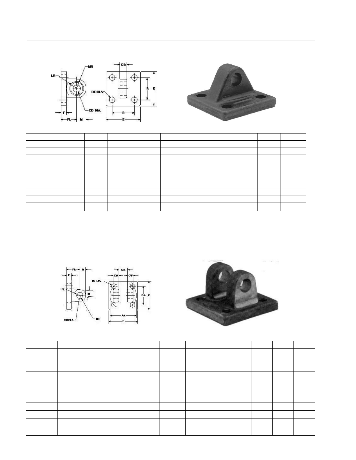
Eye Brackets
Part No. CB CD DD E F FL LR M MR R
R978935036 0.75 0.50 13/32 2.50 0.38 1.13 0.75 0.50 0.56 1.63
R978935037 1.25 0.75 17/32 3.50 0.63 1.88 1.25 0.75 0.88 2.56
R978935038 1.50 1.00 21/32 4.50 0.75 2.25 1.50 1.00 1.25 3.25
R978935039 2.00 1.38 21/32 5.00 0.88 3.00 1.13 1.38 1.63 3.81
R978935040 2.50 1.75 29/32 6.50 0.88 3.13 2.25 1.75 2.13 4.95
R978935041 2.50 2.00 1-1/16 7.50 1.00 3.50 2.50 2.00 2.44 5.75
R978935042 3.00 2.50 1-3/16 8.50 1.00 4.00 3.00 2.50 3.00 6.59
R978935043 3.00 3.00 1-5/16 9.50 1.00 4.25 3.25 3.00 3.25 7.50
R978935044 4.00 3.50 1-13/16 12.63 1.06 5.69 4.00 3.50 4.13 9.62
R978935045 4.50 4.00 2-1/16 14.88 1.31 6.44 4.50 4.00 5.25 11.50
Clevis Brackets
Part No. AA BA CB CD CW DD E F FL LR M MR
R978935046 2.3 1.63 .765 0.50 0.50 3/8 - 24 2.50 0.38 1.13 0.50 0.50 0.56
R978935047 2.9 2.06 1.265 0.75 0.63 1/2 - 20 3.00 0.63 1.88 1.00 0.75 1.06
R978935048 3.6 2.56 1.265 0.75 0.63 1/2 - 20 3.50 0.63 1.88 1.06 0.75 1.06
R978935049 4.6 3.25 1.515 1.00 0.75 5/8 - 18 4.50 0.75 2.25 1.25 1.00 1.13
R978935050 5.4 3.81 2.032 1.38 1.00 5/8 - 16 5.00 0.88 3.00 1.88 1.38 1.75
R978935051 7.0 4.94 2.531 1.75 1.25 7/8 - 14 6.50 0.88 3.13 2.00 1.75 1.88
R978935052 8.1 5.75 2.531 2.00 1.25 1 - 14 7.50 1.00 3.50 2.13 2.00 2.13
R978935053 9.3 6.59 3.032 2.50 1.50 1 1/8 - 12 8.50 1.00 4.00 2.63 2.50 2.50
R978935054 10.6 7.50 3.032 3.00 1.50 1/4 - 12 9.50 1.00 4.25 2.88 2.75 2.75
R978935055 13.6 9.63 4.032 3.50 2.00 1 3/4 - 12 12.63 1.69 5.69 3.63 3.50 3.50
R978935056 16.2 11.50 4.532 4.00 2.25 2 - 12 14.88 1.94 6.44 4.00 4.00 4.00
Page 31
RA 17038/02.13 | CDT1/CGT1 Industrial Hydraulics | Bosch Rexroth Corp. 31/44
Rexroth Cylinder Accessories
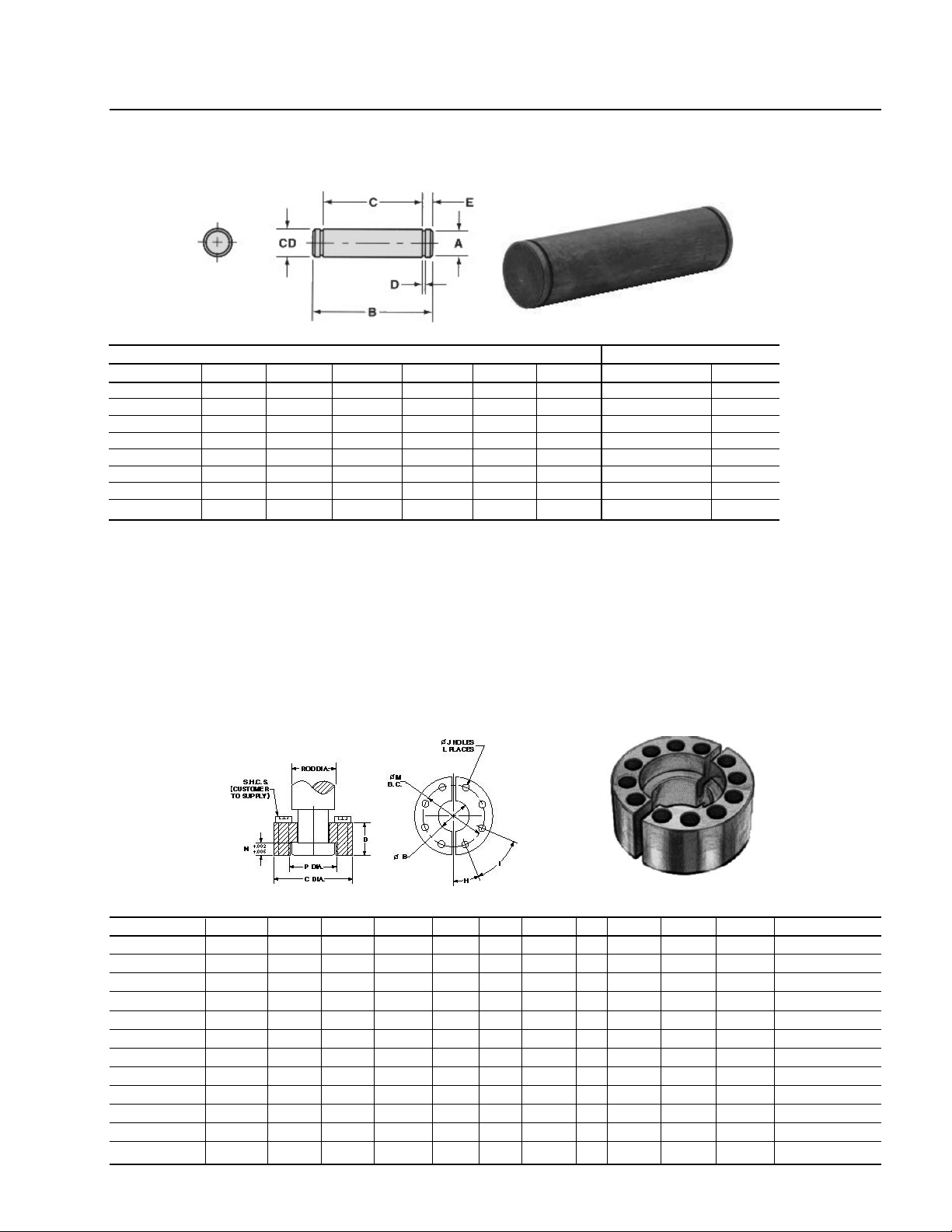
Pivot Pins-Grooved
Pivot Pins C-Rings
Part No. CD A B C D E Part No. CD
R978935026 0.500 0.468 2.094 1.875 0.041 0.109 R978000049 0.500
R978935027 0.750 0.704 2.875 2.625 0.048 0.125 R978000189 0.750
R978935028 1.000 0.940 3.375 3.125 0.048 0.125 R978000190 1.000
R978935029 1.375 1.291 4.485 4.187 0.056 0.149 R978000191 1.375
R978935030 1.750 1.650 5.547 5.188 0.068 0.180 R978000192 1.750
R978935031 2.000 1.886 5.547 5.188 0.068 0.180 R978000206 2.000
R978935032 2.500 2.360 6.625 6.188 0.086 0.219 R978000193 2.500
R978935033 3.000 2.838 6.780 6.250 0.103 0.265 R978000194 3.000
Note: When ordering pivot pins, two C-rings must also be ordered for each pin.
Pivot pins do not automatically ship with C-rings. Additional C-rings are available
in any quantity.
Safe Rod End Coupler
Part No. Rod. Dia. B C D H I J L M N P Material
R978007008 0.625 0.406 1.500 0.562 45° 90° 0.218 4 1.125 0.250 0.656 AISI 1144 CD
R978007009 1.000 0.750 2.000 0.875 30° 60° 0.218 6 1.500 0.375 1.063 AISI 1144 CD
R978007010 1.375 0.938 2.500 1.000 30° 60° 0.343 6 2.000 0.375 1.438 AISI 1018 CD
R978007011 1.750 1.187 3.000 1.250 22.5° 45° 0.343 8 2.375 0.500 1.813 AISI 1018 CD
R978007012 2.000 1.438 3.500 1.625 15° 30° 0.406 12 2.688 0.625 2.063 AISI 1018 CD
R978007013 2.500 1.875 4.000 1.875 15° 30° 0.406 12 3.188 0.750 2.625 AISI 1018 CD
R978007014 3.000 2.375 5.000 2.375 15° 30° 0.531 12 4.000 0.875 3.125 AISI 1018 CD
R978007015 3.500 2.625 5.875 2.625 15° 30° 0.656 12 4.688 1.000 3.625 C1119 MOD
R978007016 4.000 3.125 6.375 2.625 15° 30° 0.656 12 5.188 1.000 4.125 C1119 MOD
R978007017 4.500 3.625 6.875 3.125 15° 30° 0.656 12 5.688 1.500 4.625 C1119 MOD
R978007018 5.000 4.000 7.375 3.125 15° 30° 0.656 12 6.188 1.500 5.125 C1119 MOD
R978007019 5.500 4.500 8.250 3.875 15° 30° 0.781 12 6.875 1.875 5.625 C1119 MOD
Page 32
32/44 Bosch Rexroth Corp. | Industrial Hydraulics CDT1/CGT1 | RA 17038/02.13
Rexroth Cylinder Accessories
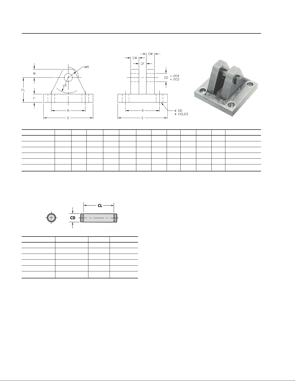
Spherical Clevis Bracket
Part No. E F M R CD CF CW DD FL LR MR Material
R901352276 3.00 .50 .50 2.05 .500 .44 .50 .41 1.50 .94 .62 Steel Weldment
R901352274 3.75 .62 .88 2.76 .750 .66 .62 .53 2.00 1.38 1.00 Steel Weldment
R978032852 5.50 .75 1.00 4.10 1.000 .88 .75 .53 2.50 1.69 1.19 Steel Weldment
R978032851 6.50 .88 1.38 4.95 1.375 1.19 1.00 .66 3.50 2.44 1.62 Steel Weldment
R901307872 8.50 1.25 1.75 6.58 1.750 1.53 1.25 .91 4.50 2.88 2.06 Steel Weldment
R901352259 10.62 1.50 2.00 7.92 2.000 1.75 1.50 .91 5.00 3.31 2.38 Steel Weldment
Pivot Pins for Spherical Clevis Bracket
Part No. CD CL Material
R901352407 .4997-.0004 1 9/16 CD1144
R901352406 .7497-.0005 2 1/32 CD1144
R978032850 .9997-.0005 2 1/2 CD1144
R978032849 1.3746-.0006 3 5/16 CD1144
R901352404 1.7496-.0006 4 7/32 CD1144
R901352400 1.9996-.0007 4 15/16 CD1144
Page 33
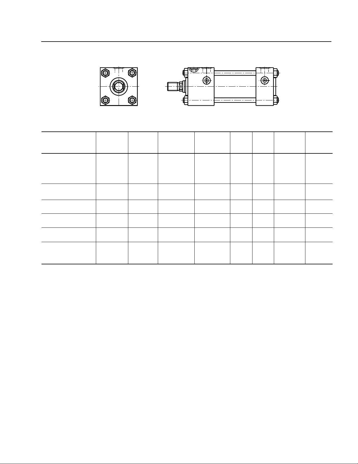
RA 17038/02.13 | CDT1/CGT1 Industrial Hydraulics | Bosch Rexroth Corp. 33/44
1
2
3
4
Port Connection Locations
Port Port Cushion Cushion Air Air Prox. Prox.
Mount Style Location Location Adjustment Adjustment Bleed Bleed Switch Swith
Head Cap Head Cap Head Cap Loc. Head Loc. Cap
MX0, MF1, MF2, MF5 1 1 2 2 4 4 3 3
MF6, MP1, MP3, MP5, 2 2 3 3 1 1 4 4
MS7, MT4, MX1, 3 3 4 4 2 2 1 1
MX2, MX3 4 4 1 1 3 3 2 2
MT1 1 1 3 2 3 4 C/F 3
3 3 1 4 1 1 C/F 1
MT2 1 1 2 3 4 3 3 C/F
3 3 4 1 2 1 1 C/F
MS2 1 1 2 2 4 4 3 3
3 3 4 4 2 2 1 1
MS3 1 1 3 3 3 3 C/F C/F
3 3 1 1 1 1 C/F C/F
MS4 1 1 2 2 4 4 C/F C/F
2 2 4 4 1 1 C/F C/F
4 4 2 2 1 1 C/F C/F
Note: Air bleed valves and piston rod cushions not available on Head or Cap ends of 1.5" bore cylinders. Air bleed valves
and cushioning not available on head end of 2" bore with 1.38" rod, 2.5" bore with 1.75" rod and 3-1/4” bore with 2” rod
size.
Page 34
34/44 Bosch Rexroth Corp. | Industrial Hydraulics CDT1/CGT1 | RA 17038/02.13
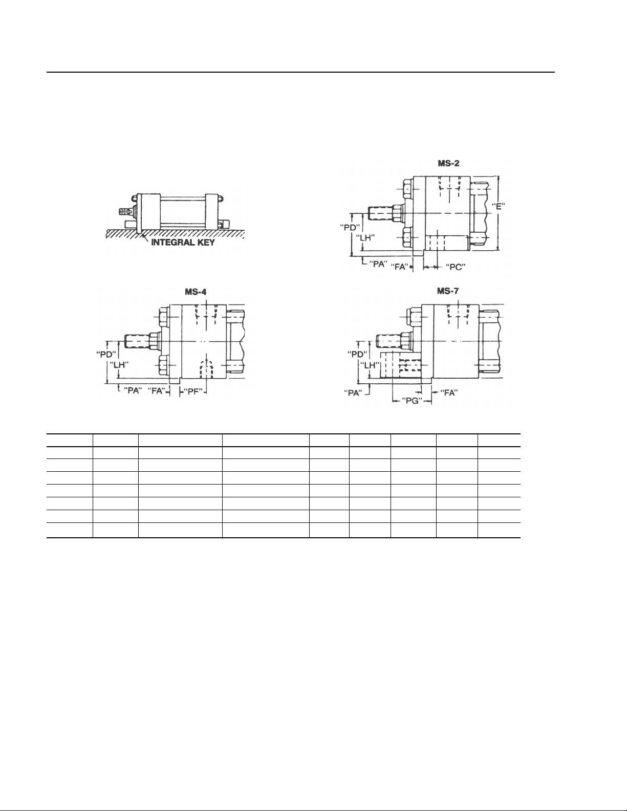
Extended Key Plates
Rexroth offers a standard arrangement of Thrust Key Mountings
on the MS2, MS4 and MS7 CDT1 cylinders. This option eliminates the need for fitted bolts or external keys to carry the thrust
load. The normal headplate is extended below the head surface
of the cylinder and is fitted in a keyway milled into the mounting
surface of the machine member. See drawing for details.
Bore E FA + 0.00 LH + 0.00 PA PC PD PF PG
1.50” 2.00 .313 - .002 0.994 - .002 0.19 0.44 1.18 1.00 1.06
2.00” 2.50 .313 - .002 1.244 - .002 0.19 0.44 1.43 1.00 1.25
2.50” 3.00 .313 - .002 1.494 - .002 0.19 0.44 1.68 1.00 1.38
3.25” 3.75 .563 - .002 1.869 - .002 0.31 0.56 2.18 1.13 1.44
4.00” 4.50 .563 - .002 2.244 - .002 0.31 0.56 2.56 1.13 1.56
5.00” 5.50 .563 - .002 2.744 - .002 0.31 0.56 3.06 1.13 1.63
6.00” 6.50 .688 - .002 3.244 - .002 0.38 0.75 3.62 1.38 1.69
Notes:
1. Use mounting bolts 0.06 smaller in diameter than hole size.
2. Fitted bolts or dowel pins are not needed with the thrust key headplate.
3. All dimensions not shown are NFPA standard.
4. PD, PA, FA dimensions typical for all mounts.
Page 35
RA 17038/02.13 | CDT1/CGT1 Industrial Hydraulics | Bosch Rexroth Corp. 35/44
40
Ø 20
M16x2
SW17
G1/8
G1/4
38
Ø 20
M16x2
SW19
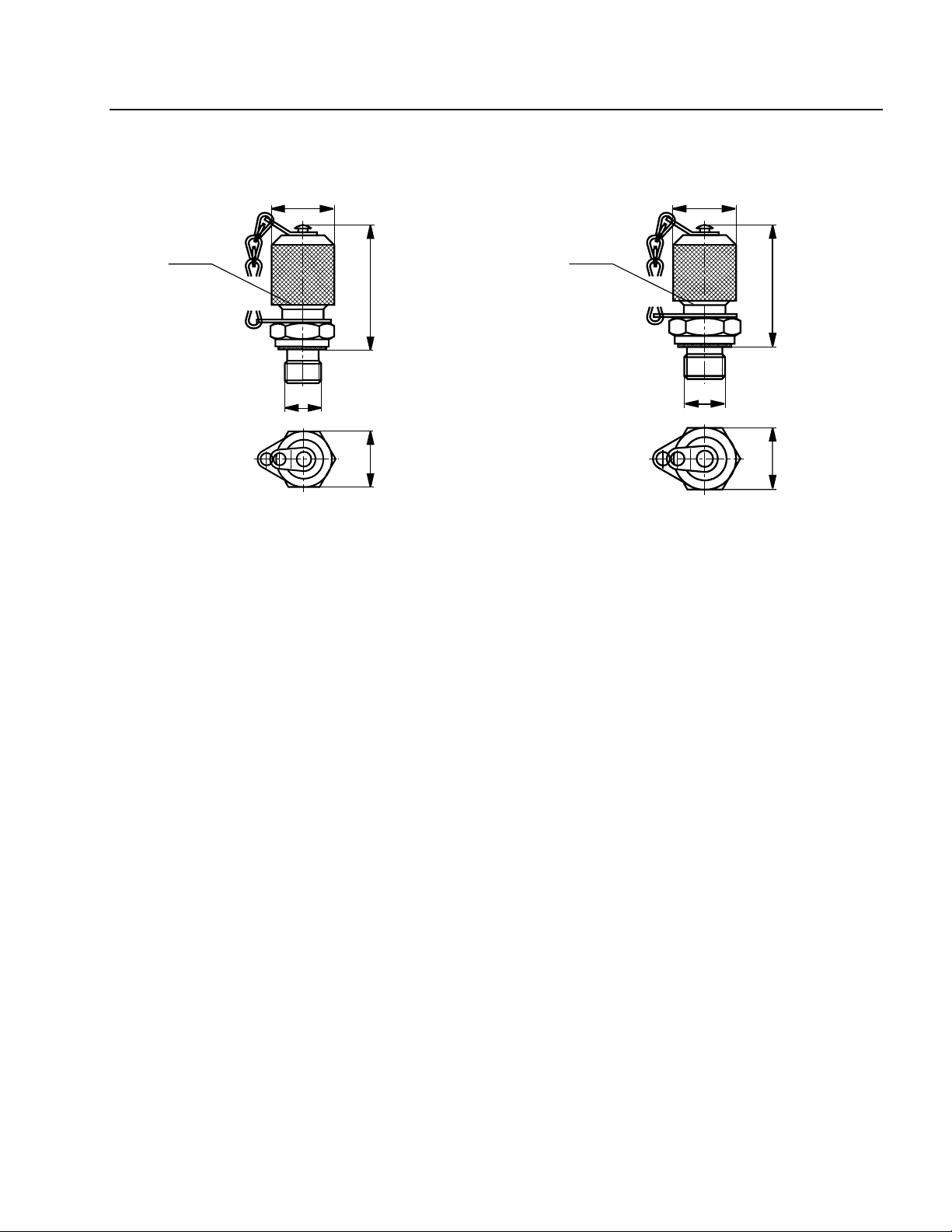
Test Point Coupling
* For bore sizes - 2“ - 2-1/2“ For Bore Sizes - 3-1/4“-8“
Above dimensions in mm.
Notes
For pressure measurement or bleeding.
For installation in the bleed/measuring port. Coupling with
check valve function, i.e. it can
also be connected under pressure.
Scope of supply for bore sizes - 2" to 2-1/2"
Coupling AB-E 20-11/K3, G 1/8
with NBR seal, Material no. R900014363
Coupling AB-E 20-11/K3V, G 1/8
with FPM seal, Material no. R900024710
Scope of supply for bore sizes - 3-1/4" to 8"
Coupling AB-E 20-11/K1, G 1/4
with NBR seal, Material no. R900009090
Coupling AB-E 20-11/K1V, G 1/4
with FPM seal. Material no. R900001264
* N/A on head end of 2" bore with 1-3/8" rod and
2-1/2" bore with 1-3/4" rod
Page 36
36/44 Bosch Rexroth Corp. | Industrial Hydraulics CDT1/CGT1 | RA 17038/02.13
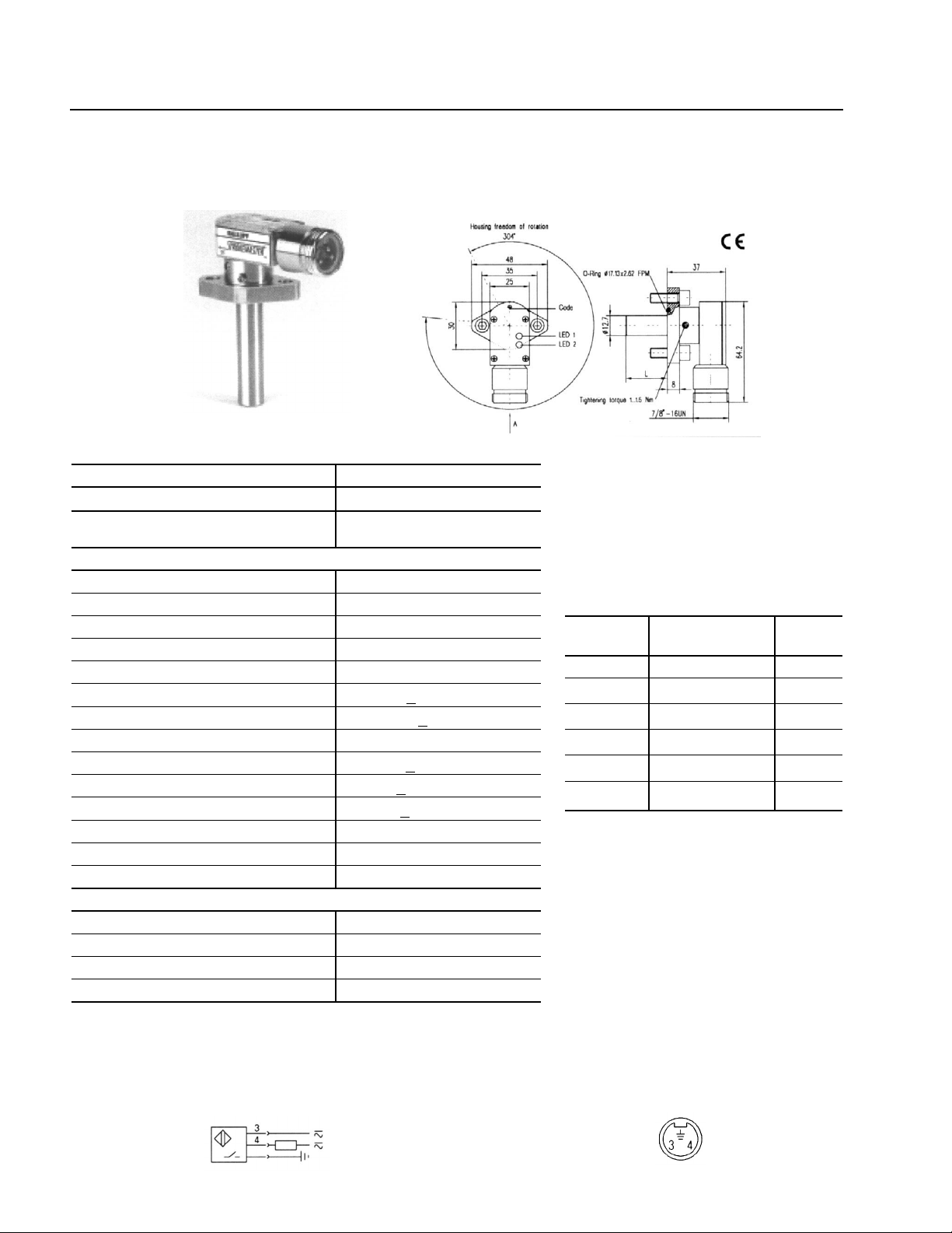
CDT1 Proximity Switch
High Pressure - 3000 psi (207 bar) Cylinder Sensors 2 wire AC/ DC Mini-Style Quick Disconnect
Dimensions (in mm)
Ordering Code Shielded (Flush Mounting)
Sensing Distance Sn 2 mm
Function
Normally Open
Electrical
Operating distance S
Supply voltage 20 - 250 V AC/DC
Supply frequency 50 / 60 Hz
Load current capacity 5 - 400 mA
Inrush current 3A (t = 20 ms)
Leakage current < 1.7 mA
Voltage drop < 6 V
Switching frequency 50 Hz
Start up delay < 150 ms
Switch hysteresis < 15% of Sn
Repeatability < 5% of Sn
Ambient temperature range -25°C to +70°C
Output function LED yes
Short circuit & overload protected yes
Mechanical
Housing material Nickel plated brass housing
Electrical connection AC Mini Style Connector
Protection class IP 67
Housing, freedom of rotation 304°
0...1.6 mm
A
Probe Part
Length Number Code
1.025 R978008781 Blue
1.250 R978008793 White
2.062 R978002203 Red
2.875 R978002204 Orange
3.775 R978008792 Silver
4.560 R978009001 Gold
Wiring Connections
2 Wire AC/DC Normally Open View of male connector pins
Page 37
RA 17038/02.13 | CDT1/CGT1 Industrial Hydraulics | Bosch Rexroth Corp. 37/44
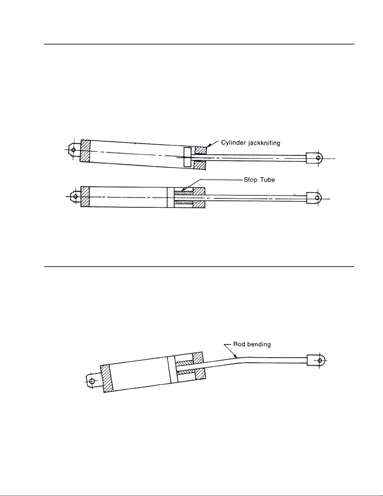
Stop Tube
In long cylinders which are pushing a load, internal stop tubes
are used to prevent excessive bearing wear and jackknifing
of the cylinder. They are installed between the piston and the
head, providing additional bearing support by increasing the
distance between the piston and the head in the fully extended
position.
For long, trouble free bearing service, the bearing loads should
not exceed about 200 psi. Standard cylinders are not designed
for heavy eccentric loads.
The use of oversize rods to reduced bearing loads is not
recommended. They are not as effective as stop tubes, and if
misalignment occurs the additional rod stiffness will actually
increase bearing loads. For long push stroke cylinders, a stop
tube may be required to limit radial bearing loads to a safe
value and prevent jackknifing. They are especially desirable in
long stroke pivoted centerline style mountings. The effect of a
stop tube may be duplicated by providing additional unused
stroke and stopping the cylinder extension by external means.
Column Strength Considerations
Standard size rods are recommended for use in cylinder applications where column strength, rod sag, or rate of cylinder
return do not require an oversize rod. Being more flexible,
standard rods absorb shock loads and minimize bearing loads
caused by misalignments.
For long push stroke cylinders, an oversize rod may be required
to prevent column failure and rod bending. Total cylinder
length, extended is considered in column strength. Refer to the
tables on the following pages for calculations regarding the column strength and stop tube required for a cylinder application.
Page 38
38/44 Bosch Rexroth Corp. | Industrial Hydraulics CDT1/CGT1 | RA 17038/02.13
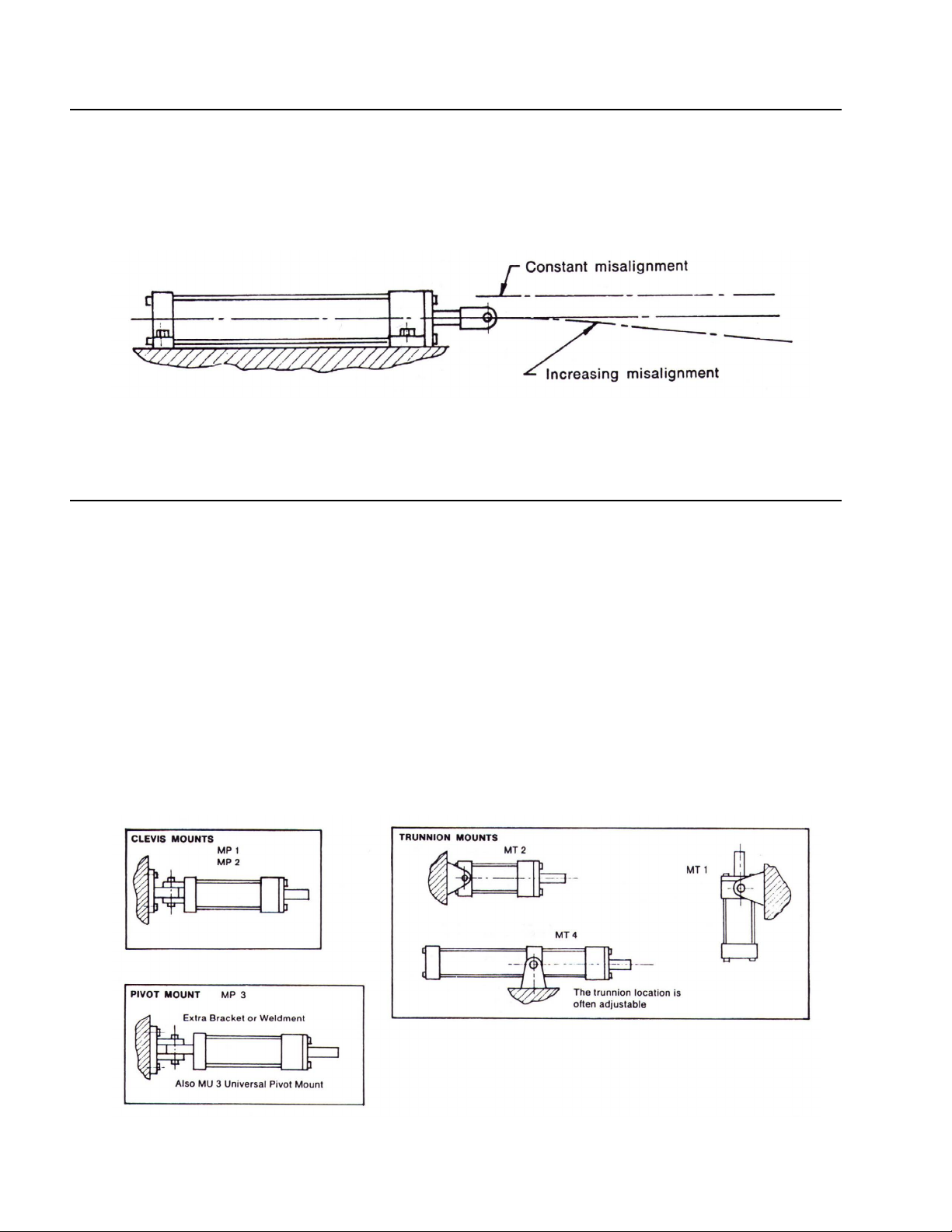
Mounting Considerations for Cylinders - Fixed Non-Centerline Mountings
Fixed mount cylinders can tolerate a slight misalignment that is
zero at full retraction and increases slightly with stroke. With other
than very large rods, a misalignment of about .003" to .005" per
foot of stroke is usually permissable. Rigid mounted cylinders cannot tolerate a fixed misalignment, particularly at full retraction.
Mounting Considerations for Cylinders - Pivoted Centerline Mountings
If the path of the load is curved or misalignment is a problem,
a pivoted centerline mounting should be used. This compensation of nonlinear travel is in one plane only, as would occur during the operation of a lever. Pivot mounts require the rod end
attachment to also be a pivot type. Close tolerance pins should
be used and it is recommended that the cylinder manufacturer's accessory brackets be used to maintain good fits.
For short strokes, medium or smaller bore cylinder applications,
the clevis mount is recommended. This is probably the most
widely used cylinder mounting. Where the clevis mount should
normally be used, but would cause the overall length of the
cylinder to be excessive, the cap trunnion mount can be used.
Head end trunnions should be carefully applied to either short
strokes or to application where the weight of the cylinder falls
vertically below the pin.
For long stroke cylinders and/or heavy cylinders, the center
or intermediate trunnion mount is recommended. This mount
supports the weight of the cylinder and should be located near
the balance point of the cylinder at the time of maximum thrust.
For general applications, a good estimate for the location of the
intermediate trunnion is 1/3 back from the head end.
The MP5 (universal) type mount is a pivot mount with a spherical bearing fitted into the pivot to permit 5 to 10 degrees of
movement in a plane perpendicular to the major plane of pivot
movement. It is probably the most serviceable of the pivoted
centerline mounts. For maximum effectiveness, a spherical
bearing type rod end fitting should be utilized at the same time.
Page 39

RA 17038/02.13 | CDT1/CGT1 Industrial Hydraulics | Bosch Rexroth Corp. 39/44
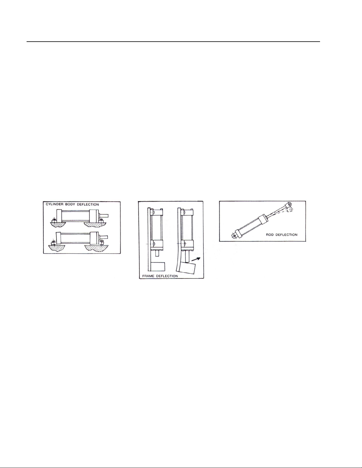
Mounting Considerations for Cylinders - Fixed Centerline Mountings
These mounting styles, illustrated below, tend to be more
stable against sway on the power extension stroke. Rigid
machine frame members are required to prevent misalignment
under loads. The travel path of the rod end should be linear
and be guided if at all possible. Long supported extension of
the rod end must be avoided. Refer to the stop tube calcula-
tion data which shows the advantages of supporting and using
reliable guiding on the rod end. Long stroke cylinders with fixed
end mounts may require additional support at the free end of
the cylinder body. This is illustrated in dotted outlines in the
sketches below.
Mounting Considerations for Cylinders - Fixed Non-Centerline Mountings
These types of mounts are perhaps the easiest to use for
mounting and replacement ease. The offset thrust line introduces bending stresses and additional loads on the mounting bolts. This type should be very well aligned for maximum
service life. The load must travel in a very linear path and be
supported and guided both horizontally and vertically as the
data for calculating stop tube and column strength illustrates.
When applying these mounts with offset thrust under high
pressure or shock loads, properly located shear pins or keys
can be used. These provide positive location and prevent slight
movement of the cylinder under shock conditions, which the
normal clearance in the mounting bolt holes would allow. Very
close tolerances (.001") should be maintained between keys
and keyways. Keys should be located as illustrated below, at
one end of the cylinder. When using dowel pins, do no pin
across opposite corners, as serious twisting stresses will
result.
Page 40
40/44 Bosch Rexroth Corp. | Industrial Hydraulics CDT1/CGT1 | RA 17038/02.13
Mounting Considerations for Cylinders
Selection of mounting style depends primarily upon the operating specifications of the application. Mountings are generally
one of the following three types:
1. Fixed Centerline Mountings
Where the thrust of the cylinder is focused on the
centerline of the cylinder rod.
2. Fixed Non-Centerline Mountings
Where the thrust of the cylinder is aligned parallel to,
but not on, the centerline of the cylinder rod.
3. Pivoted Centerline Mountings
Where the centerline of the cylinder may swing in one or
more directions. Usually major movement is in one plane.
A very important general consideration is to keep the cylinder
thrust as close as possible to the centerline of the piston rod
and free from misalignment or side thrust. Off-center thrust or
side loads subtract substantially from the anticipated rod bearing and rod seal service life.
Off-center thrust and side loading can be caused by cylinder
deflection under load, machine frame deflection, rod bending
or sagging, cylinder pivot binding, nonlinear load movement,
shifting of load; some of which are shown below.
In addition to the mounting styles, several other factors should
be considered when mounting a cylinder. Care should be taken
to avoid painting or damaging the exposed portion of the piston rod during construction. Threaded pieces should be pulled
tight against thread shoulders to minimize bending and reduce
fatigue stress. Rotation of the piston rod within the cylinder
should be avoided to prevent possible scoring of the cylinder
tube and damage to piston seals. Long cylinders may require
additional body support to prevent damaging sag.
Major consideration must be given to the factors which might
cause premature failure of the cylinder: unusual acceleration,
unusual deceleration, alignment, support of cylinder weight,
linear or curvilinear travel path of the load being moved, jackknifing of the cylinder, and the column strength of the rod.
Some mounting styles are more suited than others to each of
the above application factors.
Page 41
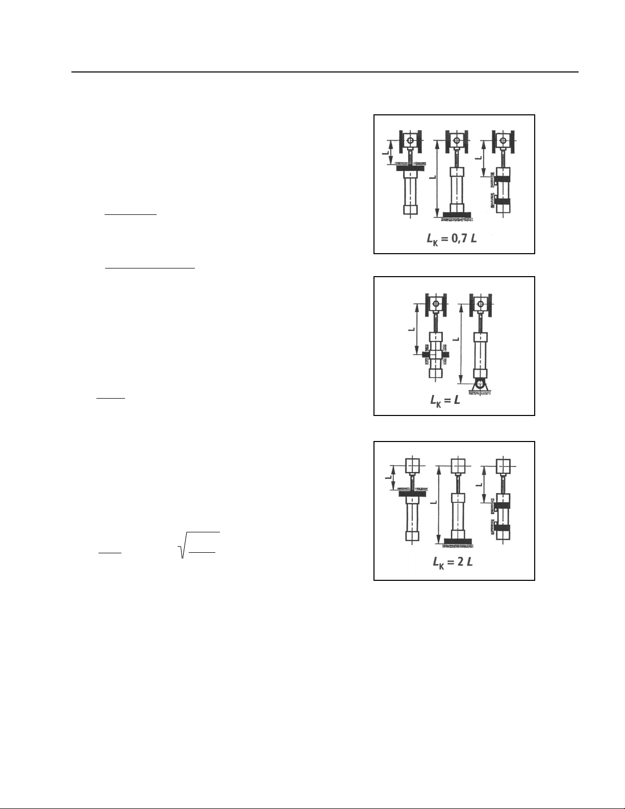
RA 17038/02.13 | CDT1/CGT1 Industrial Hydraulics | Bosch Rexroth Corp. 41/44
Buckling
The permissible stroke with a flexible guided load and a 3.5
factor of safety against buckling can be obtained from the
relevant table. For deviating cylinder installation positions, the
permissible stroke length has to be interpolated. Permissible
strokes for non-guided loads on request.
Calculations for buckling are determined using the following
formulas:
1. Calculation according to Euler
π 2 • E • I
F = if λ > λg
ν • L
2
K
2. Calculation according to Tetmajer
d 2 • π (335 – 0.62 • λ)
F =
4 • ν
if
λ ≤ λg
Explanation:
E = Modulus of elasticity in psi
= 30 x 106 for steel
I = Moment of inertia in inches4 for circular cross-sec-
tional area
Influence of the mounting type on buckling length:
A
B
d
= = 0.0491 • d
64
4
• π
4
ν = 3.5 (safety factor)
LK = Free buckling length in inches
(depending on mounting type,
see sketches A, B, C)
d = Piston rod Ø in inches
λ = Slenderness ratio
4 • L
= λg = π
K
d 0.8 • R
E
e
Re = Yield strength of the piston rod material
C
Page 42
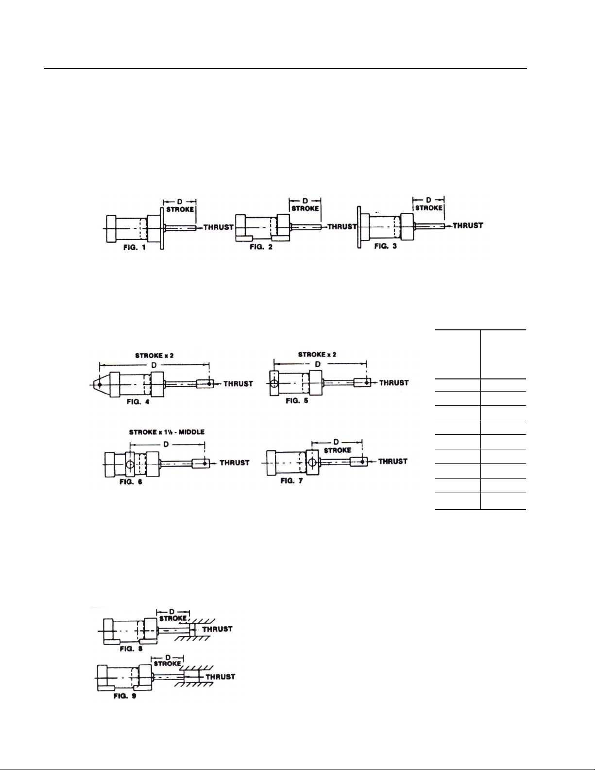
42/44 Bosch Rexroth Corp. | Industrial Hydraulics CDT1/CGT1 | RA 17038/02.13
Stop Tube
To determine whether a stop is required on push stroke cylinders:
Step 1 - Determine which example below corresponds to your
application.
Step 2 - Determine the value of "L" from the instructions given.
The find "L" dimension in the table at the right for the required
stop tube length. (Specify the effective stroke plus the stop
tube length when ordering).
Typical rigidly mounted cylinders with rod unsupported at free end. May be mounted either horizontally or
vertically. Use the equation L = 4D to determine values of "L" for all cylinder mountings in this category.
Step 3 - Add stop tube length to original "L" dimension to
obtain your adjusted "L" dimension.
Example: "L" = 96", therefore, Stop Tube = 6"
Adjusted L = 102" (96+6)
Step 4 - Use adjusted "L" to figure rod column strength at
maximum pressure rating of the cylinder, page 34.
Stop
"L" Tube
Inches Length
(inches)
0-40 0
41-50 1
51-60 2
61-70 3
71-80 4
81-90 5
91-100 6
101-110 7
111-120 8
Typical trunnion mounted cylinders may be mounted either horizontally or vertically. Use the equation L = D to determine values of "L" for all cylinder mountings in this category. For center trunnion
mounted cylinders (Figure 6), the position of the trunnion for most favorable bearing loads is obtained
when "D" dimension with the rod retracted is approximately 1/3 overall length of cylinder with rod
retracted.
Typically rigidly mounted cylinder with free end of rod
supported with short guide. May be mounted either
horizontally or vertically. Use the equation L = D to
determine values of "L" for all cylinder mountings in
this category.
Typical rigidly mounted cylinder with free end of
rod supported with long closely-fitted guide. May
be mounted either horizontally or vertically. Use the
equation L = 1/2 D to determine values of "L" for all
cylinder mountings in this category.
Page 43

RA 17038/02.13 | CDT1/CGT1 Industrial Hydraulics | Bosch Rexroth Corp. 43/44
Column Strength and Oversize Rod Selection
Standard rod diameters are recommended for all Pull Stroke
applications. To determine the correct rod diameter required
for Push Stroke application, follow these simple steps:
Step 1 – Determine the value of "L
shown on page 40. (Use Adjusted "L
“ from the illustrations
K
" dimension for cylinder
K
with Stop Tube).
Step 2 – From your cylinder size and maximum operating pressure, determine your Push Stroke Thrust.
Step 3 – Find your thrust in the left hand column and located
your "L
horizontal line to the right; (if your exact "L
" dimension (or Adjusted "LK" dimension in the same
K
" or adjusted "LK"
K
dimension is not shown, move to the right in the same horizontal column to the next larger number). Read vertically up from
this number to the rod diameter shown. This is the required rod
diameter for your application.
Example: Adjusted L
of 80" at 16,000# would required 2-
K
1/2" rod in the cylinder.
Thrust Rod Diameters
in Pounds
Force at End 0.500 0.625 1.000 1.375 1.750 2.000 2.500 3.000 3.500 4.000 4.500 5.000 5.500
of Rod
50 60 67
100 43 58 110
150 35 53 103
250 27 43 94 146
400 21 37 83 134 186
700 16 30 68 118 168 202 275
1,000 13 27 60 105 155 190 257 330
1,400 11 24 53 92 142 174 244 308 385
1,800 10 22 48 82 127 160 230 296 366 440
2,400 9 19 45 75 114 145 213 281 347 415 488
3,200 8 16 41 67 103 130 194 261 329 400 461
4,000 7 13 38 63 94 119 175 240 310 378 446
5,000 6 9 34 60 87 110 163 225 289 360 426 494
6,000 30 56 82 102 152 208 274 342 410 476
8,000 26 50 76 93 137 188 245 310 375 447
10,000 21 45 70 89 125 172 222 279 349 412 485
12,000 17 41 65 84 118 152 210 269 326 388 454
16,000 34 57 75 110 142 188 235 292 350 420
20,000 28 52 68 103 136 172 218 270 326 385
30,000 39 55 87 120 156 189 230 285 330
Values of "LK" (inches)
Page 44
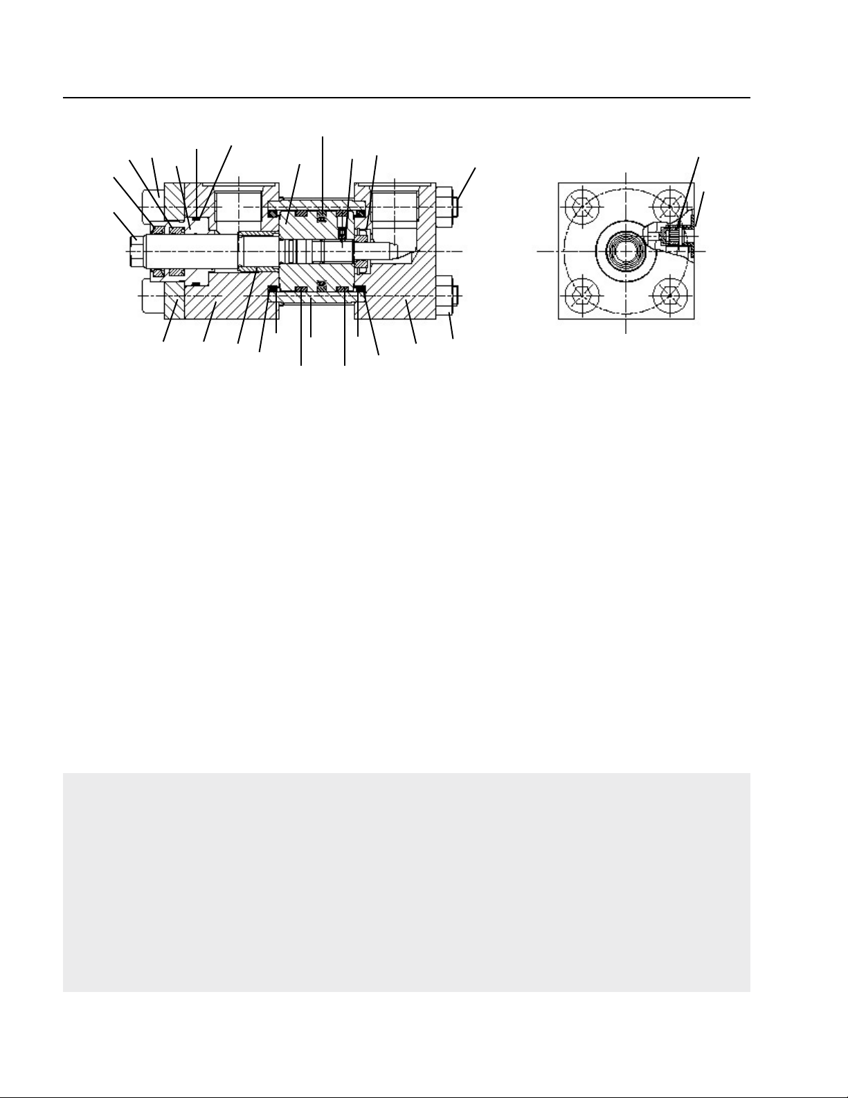
44/44 Bosch Rexroth Corp. | Industrial Hydraulics CDT1/CGT1 | RA 17038/02.13
Spare Parts CDT1
17b
9
17a
14
17c
17d
15
5
1
17e
6
17f
1 Head
2 Tube
3 Piston
4 Cap
5 Flange
6 Cushion bushing
7 Cushion insert w/retainer
8 Tie rod
9 Piston rod
10 Bleed screw
11 Securing plate
12 Tie rod nut
13 Set screw
14 Hex head bolt
3
17h
17g
2
17h
13
17e
7
8
12
17f
4
15 Rod bearing
16 Cushion valve
(not shown)
17 Seal kit:
a. Rod seal
b. Wiper
c. Bearing o-ring
d. Bearing back-up ring
e. Tube o-ring
f. Tube back-up ring
g. Piston seal
h. Wear bands
10
11
See service manual RA17038-DT1SM/10.07 for installation and assembly instructions and replacement part numbers.
Bosch Rexroth Corporation
Industrial Hydraulics
2315 City Line Road
Bethlehem, PA 18017-2131
USA
Telephone (610) 694-8300
Facsimile (610) 694-8467
www.boschrexroth-us.com
© Bosch Rexroth Corporation
All rights reserved. Neither this document nor any part of it may be reproduced, duplicated circulated or disseminated, whether by copy, electronic
format or any other means, without the prior consent and authorization of
Bosch Rexroth Corporation.
The data and illustrations in this brochure/data sheet are intended only to describe or depict the products. No representation or warranty, either express
or implied, relating to merchantability or fitness for intended use, is given or
intended by virtue of the information contained in this brochure/data sheet.
The information contained in this brochure/data sheet in no way relieves the
user of it obligation to insure the proper use of the products for a specific
use or application. All products contained in this brochure/data sheet are
subject to normal wear and tear from usage.
Subject to change.
 Loading...