

Bosch WTA34, WTA35 Repair Instructions

REPAIR INSTRUCTIONS
r120085e
-15/1
04.99
TUMBLE DRYER
Vented WTA34.. / WTA35..
I. SAFETY INFORMATION Page 1
II. OPERATION Page 1
III. DESCRIPTION OF FUNCTION / TECHNICAL INFORMATION Page 2
IV. CONSUMPTION RATES / ENERGY REQUIREMENT / OTHER DATA Page 6
V. REPAIRS Page 7
VI. SUPPLEMENTS Page 13
I. SAFETY INFORMATION
Before commencing repairs, ALWAYS disconnect the appliance from the power supply!
If tests have to be performed while the appliance is live, ALWAYS use a residualcurrent-operated circuit-breaker! When repairs are complete, perform a function test, as
well as a safety test in accordance with VDE 0701.
1. Safety test in accordance with VDE 0701
• Plug in the tester mains plug.
In the case of switchover models connect L1 and L2 on the tester.
• Switch on the appliance (door must be closed).
• Perform the test.
II. OPERATION
1. Selecting the programme
• “Cottons/coloureds” Turn the programme selector in a clockwise direction to the
desired drying setting (6 automatic drying settings).
• Easy-care Turn
the programme selector in an anti-clockwise direction to the
desired setting (5 automatic drying settings).
• Timed programme Turn programme selector / time switch to the desired time.
2. Buttons
• ON/OFF Switches the appliance on / off.
• “Low heat” For delicate textiles. The temperature is reduced.
TUMBLE DRYER
r120085e
-15/2
04.99
• Signal Button
pressed (LED on) – signal emitted in the “anti-creasing”
phase.
Changing
the v
olum
e – h
old dow
n the b
utton
, the s
igna
l c
hanges
.
When the button is released, the volume has been changed
and stored.
Switching off the signal – press the button again (LED off).
• Start time* The start time can be specified from 1–19 hours. The running
time is indicated by a flashing dot in the 7-segment display.
The “anti-creasing” phase is extended to 8 hours.
If the Start button is pressed, the appliance starts immediately.
If the door is opened during the preselected time,
the Start time LED flashes, press the Start time button again –
the LED switches to a steady light.
* Optional (WTA3480; WTA3500)
3. Programme progress indicator
Dampness in the washing is continuously checked by the electronic sensor system.
The programme status is displayed by an LED.
III. DESCRIPTION OF FUNCTION / TECHNICAL INFORMATION
1. General information
The
design is based on a fully electronic solution. All control functions are combined on the
power
module. The selected drying setting is
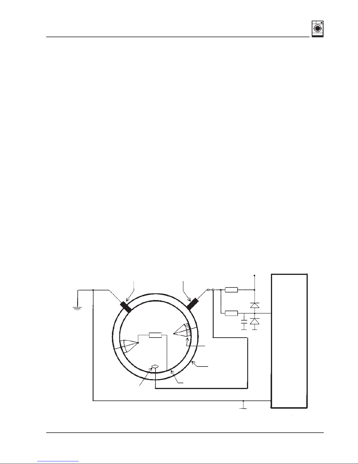
determined by a conductivity measurement.
The conductivity measurement of the washing is converted to a voltage measurement.
Sliding contact
earth
Washing
resistance
Sliding contact
driver electrode
Sliding contact
driver electrode
Insulation
Slipring
Drum wall
Input
Micro-
controller
+5 V
TUMBLE DRYER
r120085e
-15/3
04.99
• Operating and display module is situated in the fascia.
• Control and power module is situated on the right frame support.
• Thermistor sensor for measuring the air temperature.
• Condensation
pump is situated in the base group underneath the belt tensioning device.
• Motor is situated on the right in the base group.
• Heater on the rear panel – under the heating duct cover.
• Bimetallic thermal cut-out (>170 °C) is situated directly on the heater.
1.1 Operating and display module
The
operating and display module is used to input and output
information. It houses all the
direct input buttons, all signalling elements, e.g. LEDs, selector switches and signal
transmitters. Models are encoded by breaking off the side bridges.
1.2 Control and power module
The module houses all the significant components, e.g. micro-controller, relays, power
supply, etc. It performs complex functions with respect to controlling drying sequences,
monitoring the temperature, ascertaining parameters and actuating the operating and
display
section. The appliance is switched over from 16 A to 10 A by means of a wire jumper
.
Wire
jumper closed 16 A – Wire jumper open 10 A. Control and power module ≥ mask V 4.00
(software
version is indicated on the processor) changes automatically from 16 A to 10 A.
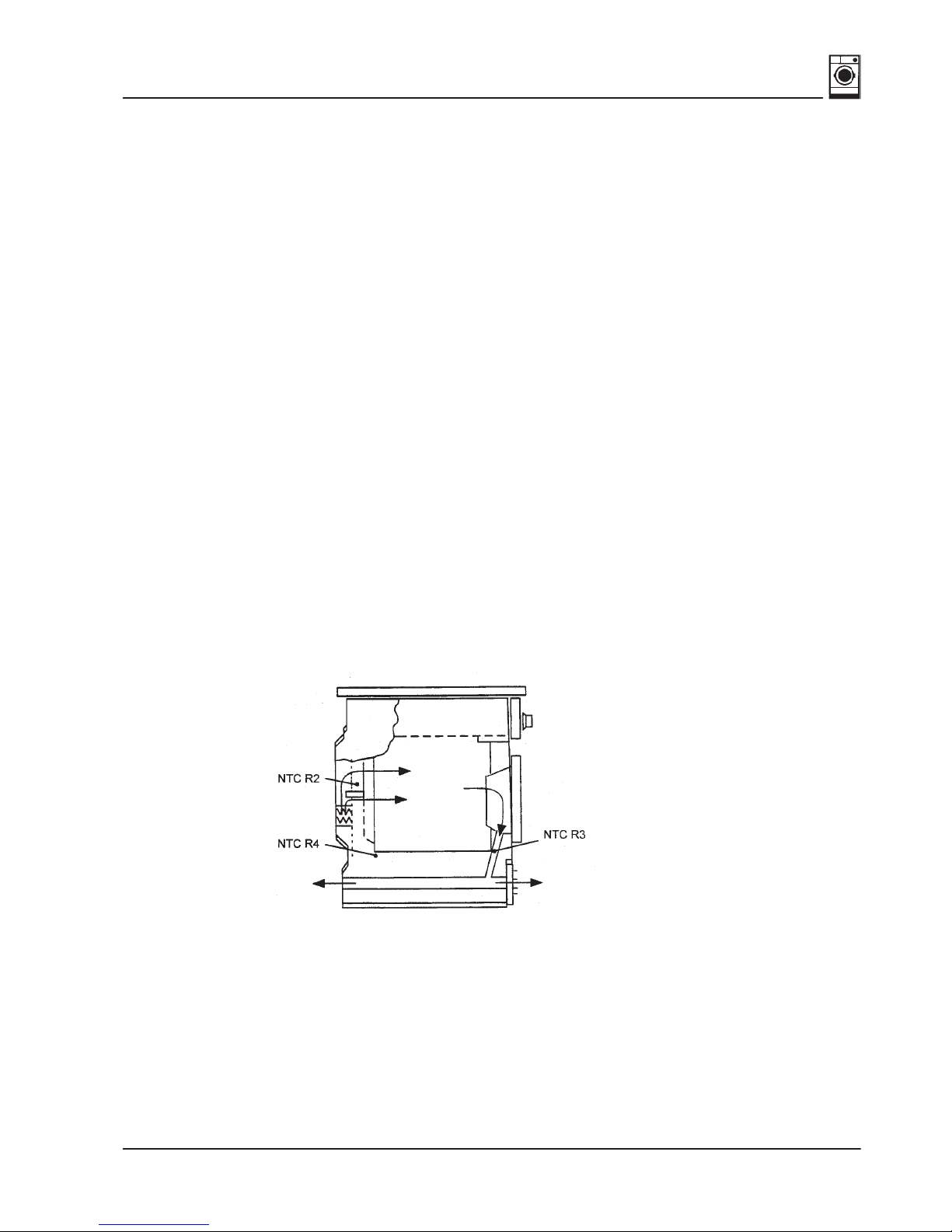
1.3 Thermistor sensor for measuring the air temperature
Thermistor
sensors measure the temperature of the process air at three dif
ferent points
in
the appliance (NTC thermistor – NTC stands for Negative Temperature Coefficient).
NTC R3
is situated in the ring insert under the door and measures the exhaust-air temperature.
NTC R4
is situated in the air current in front of the heater.
TUMBLE DRYER
r120085e
-15/4
04.99
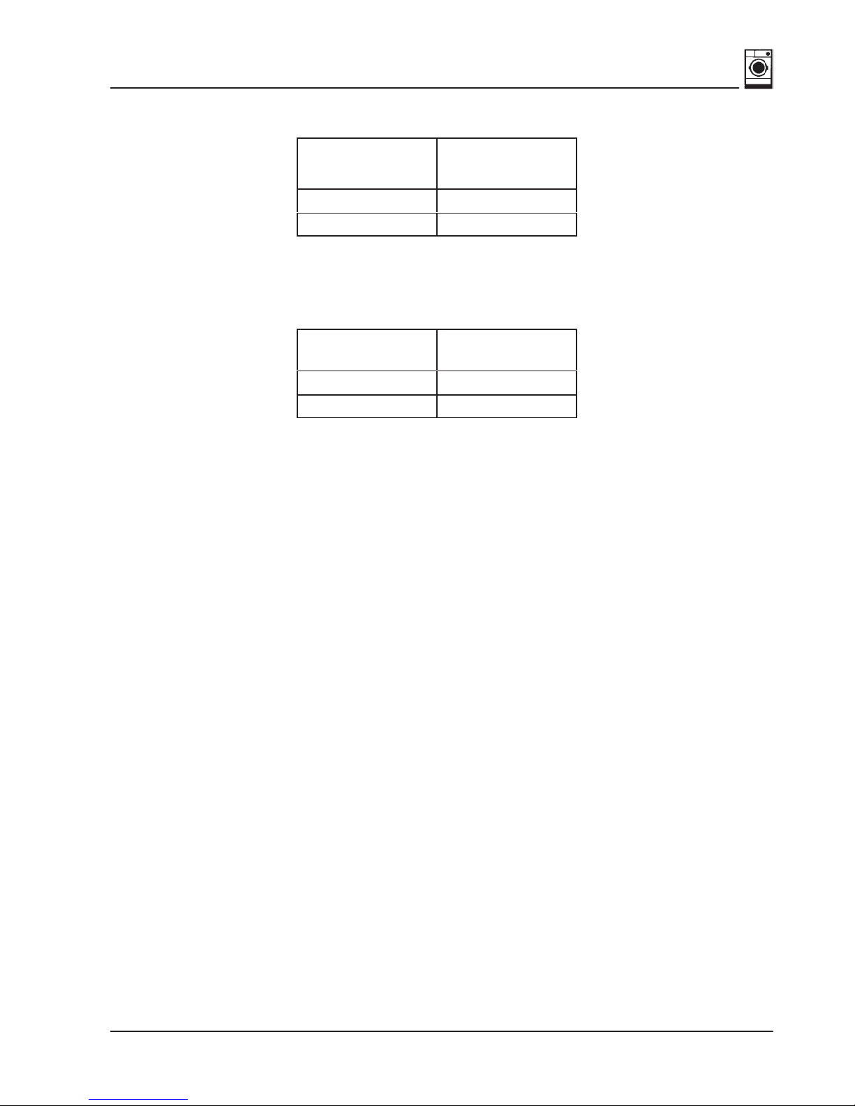
Resistance values NTC R3 / NTC R4
Temperature
°C
Resistance
kΩ
25 9–11
60 2.3–2.7
NTC R2
is
situated above the heater and measures the temperature
of the process air blown into the
washing.
Temperature
°C
Resistance
kΩ
25 18–22
60 4.5–5.5
1.4 Motor
The motor drives the drum and the fan.
Specifications:
Rated input when appliance empty: 140 W
Current input when appliance empty: 0.5 A
Motor capacitor, capacity: 11 µF
Nominal frequency: 50 Hz
Nominal voltage: 230 V
1.5 Heater
The heater consists of two heating coils E2, E3, the bimetallic thermal cut-out B9 and the
NTC R2.
Heat setting 2: 1200 W
Heat setting 3: 1800 W
1.6 Bimetallic thermal cut-out (heater)
The
thermal cut-out should respond when localised overheating occurs, e.g. if the air flow or
electrical temperature control fails.
If a fault occurs, the thermal cut-out must be manually actuated by pressing the red reset
button.
Response temperature: 160–175 degrees Celsius
1.7 Door switch and safety functions
All
relay activations are controlled via the door switch.
When the door is open, relays cannot
be activated.
When
the door is closed and the mains switch is on, the capacitor is charged via a processor
output. Its voltage is monitored by an analogue input.
TUMBLE DRYER
r120085e
-15/5
04.99
When the door is opened, the capacitor is discharged. If a voltage of less than 1.5 V is
measured
on the capacitor when the machine is switched on, either
the door was opened or
a
mains failure lasted too long while the appliance was switched of
f. The programme must
then
be restarted. If the voltage on the capacitor is still suf
ficiently high, the programme is
reset and restarted following a voltage interruption.
Door switch F1
Closed Open
Micro-controller
Output
Analogue input
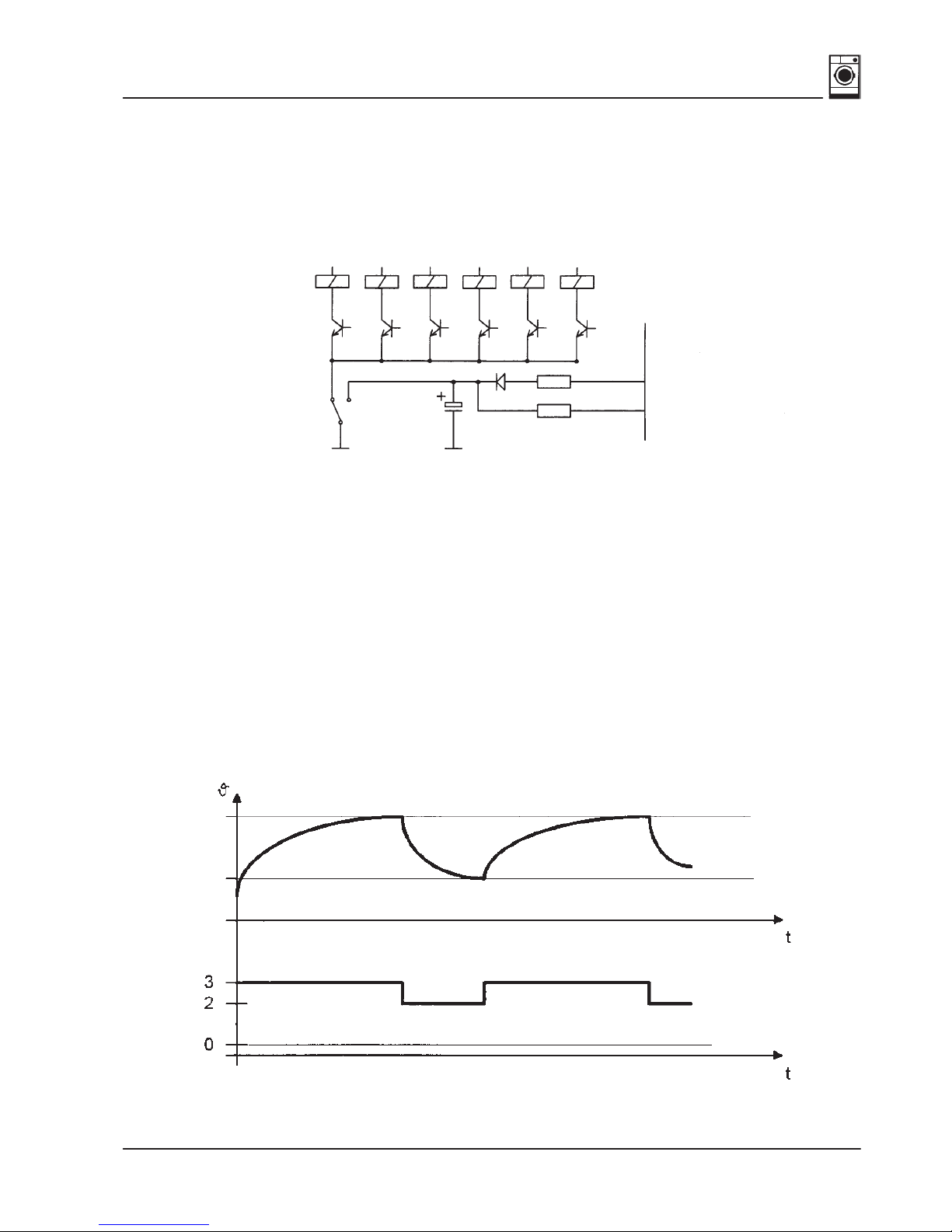
2. Principle of heating control
As the heater consists of 2 phase windings which operate at different power levels,
a different heating control can be used at various heat settings.
Heat setting 0 = OFF
Heat setting 2 = E3
Heat setting 3 = E2 + E3
The heat setting which is active is dependent on the programme sequence and on the
temperatures behind the heater (NTC R2) and on the drum outlet (NTC R3). If the motor
rotates in an anti-clockwise direction, the current heat setting is reduced by one
(Heat setting 3 ⇒ Heat setting 2 or Heat setting 2 ⇒ Heat setting 0).
Max.
Min.
Heat
setting
The maximum heat settings and minimum temperature values (NTC R2, NTC R3)
permitted for a programme section have been defined in the drying programme.
Both temperatures are monitored in parallel, the reset temperature having higher priority.
 Loading...