

Bosch WT 11 AM1 E Installation And User Instructions Manual
Installation and Users Instructions
Gas water heaters
WT 11 AM1 E
6 720 607 800 (2016/02) GB
Read installation manual prior to installation of this unit!
Read user manual before putting this unit in operation!
Observe the warnings in the manuals!
The installation room must fulfill the ventilation requirements!
Installation by an authorised person only!

6 720 607 800 (2016/02)
2 | Table of contents
Table of contents
1 Key to symbols and safety instructions . . . . . . . . . . 3
1.1 Key to symbols . . . . . . . . . . . . . . . . . . . . . . . 3
1.2 Safety Instructions . . . . . . . . . . . . . . . . . . . . 3
2 Appliance specifications . . . . . . . . . . . . . . . . . . . . . . 4
2.1 Declaration of conformity with relevant EEC
regulations . . . . . . . . . . . . . . . . . . . . . . . . . . 4
2.2 Technical Identification code . . . . . . . . . . . . 4
2.3 Appendices . . . . . . . . . . . . . . . . . . . . . . . . . . 4
2.4 Description . . . . . . . . . . . . . . . . . . . . . . . . . . 4
2.5 Special Accessories . . . . . . . . . . . . . . . . . . . 4
2.6 Dimensions . . . . . . . . . . . . . . . . . . . . . . . . . . 5
2.7 Electrical layout . . . . . . . . . . . . . . . . . . . . . . . 6
2.8 Operational instructions . . . . . . . . . . . . . . . . 6
2.9 Technical data . . . . . . . . . . . . . . . . . . . . . . . . 7
2.10 Product data on energy consumption . . . . . 8
3 Use . . . . . . . . . . . . . . . . . . . . . . . . . . . . . . . . . . . . . . . . . 9
3.1 Before operating the appliance . . . . . . . . . . 9
3.2 Connect and disconnect the appliance . . . . 9
3.3 Regulation of water temperature . . . . . . . 10
3.4 Breakdown indication . . . . . . . . . . . . . . . . 10
3.5 Purge appliance . . . . . . . . . . . . . . . . . . . . . 10
4 Flue accessories . . . . . . . . . . . . . . . . . . . . . . . . . . . . 11
4.1 Flue Accessories . . . . . . . . . . . . . . . . . . . . 11
4.1.1 Vertical flue . . . . . . . . . . . . . . . . . . . . . . . . 11
4.1.2 Fitting the restrictor plate . . . . . . . . . . . . . 11
4.1.3 Horizontal flue . . . . . . . . . . . . . . . . . . . . . . 13
4.1.4 Fitting the restrictor plate . . . . . . . . . . . . . 13
5 Regulation . . . . . . . . . . . . . . . . . . . . . . . . . . . . . . . . . 14
6 Installation . . . . . . . . . . . . . . . . . . . . . . . . . . . . . . . . 15
6.1 Important . . . . . . . . . . . . . . . . . . . . . . . . . . 15
6.2 Selection of location for installation . . . . . 15
6.3 Minimum distances . . . . . . . . . . . . . . . . . . 16
6.4 Installation of support bar . . . . . . . . . . . . . 16
6.5 Installation . . . . . . . . . . . . . . . . . . . . . . . . . 16
6.6 Water connection . . . . . . . . . . . . . . . . . . . 17
6.7 Gas connection . . . . . . . . . . . . . . . . . . . . . 17
6.8 Inlet/exhaust pipe installation . . . . . . . . . 17
7 Electrical connection . . . . . . . . . . . . . . . . . . . . . . . 18
7.1 Connection . . . . . . . . . . . . . . . . . . . . . . . . 18
7.2 Power cable . . . . . . . . . . . . . . . . . . . . . . . . 18
8 Gas regulation . . . . . . . . . . . . . . . . . . . . . . . . . . . . . 18
8.1 Factory regulations . . . . . . . . . . . . . . . . . . 18
8.2 Pressure regulation . . . . . . . . . . . . . . . . . . 19
8.3 Changing gas type . . . . . . . . . . . . . . . . . . . 20
9 Maintenance . . . . . . . . . . . . . . . . . . . . . . . . . . . . . . . 20
9.1 Periodic maintenance tasks . . . . . . . . . . . 21
9.2 Startup after maintenance . . . . . . . . . . . . 21
9.3 Changing fuses (control box) . . . . . . . . . . 21
9.4 Temperature range selection . . . . . . . . . . 21
10 Problems . . . . . . . . . . . . . . . . . . . . . . . . . . . . . . . . . . 22
11 Environmental protection . . . . . . . . . . . . . . . . . . . 23
6 720 607 800 (2016/02)
Key to symbols and safety instructions | 3
1 Key to symbols and safety instructions
1.1 Key to symbols
Warnings
The following keywords are defined and can be used in this
document:
• NOTICE indicates a situation that could result in damage to
property or equipment.
• CAUTION indicates a situation that could result in minor to
medium injury.
• WARNING indicates a situation that could result in severe
injury or death.
• DANGER indicates a situation that will result in severe
injury or death.
Important information
Additional symbols
1.2 Safety Instructions
If there is a smell of gas:
▶ Close the gas valve.
▶ Open windows.
▶ Do not connect any electrical apparatus.
▶ Extinguish any naked flames.
▶ Phone the gas company or an authorized technician from a
safe distance.
If there is a smell of burnt gases:
▶ Disconnect the appliance.
▶ Open doors and windows.
▶ Inform an installation company.
Fitting, modifications
▶ The fitting and modification of the installation of the
appliance must be carried out only by an authorized
technician.
▶ The pipes carrying burnt gases must not be modified.
▶ Do not close or reduce air circulation holes.
Maintenance
▶ The user must maintain and periodically service the
appliance.
▶ The user is responsible for the safety and environmental
compatibility of the installation.
▶ The appliance should be serviced annually.
▶ Only original spare parts should be used.
Explosive and inflammable materials
▶ Inflammable materials (paper, solvents, ink, etc.) should
not be stored near the appliance.
Combustion air and ambient air
▶ To avoid corrosion, combustion air and ambient air should
be free of aggressive substances (for example halogenated
hydrocarbons containing chlorine and fluoride
composites).
Client information
▶ Inform the client about the function and operation of the
appliance.
▶ Caution clients against performing modifications or repairs
themselves.
Safety of electrical appliances for
domestic use and similar purposes
The following requirements apply in
accordance with EN 60335-1 in order to
prevent hazards from occurring when using
electrical appliances:
“This appliance can be used by children of 8
years and older, as well as by people with
reduced physical, sensory or mental
capabilities or lacking in experience and
knowledge, if they are supervised and have
been given instruction in the safe use of the
Warnings in this document are identified by
a warning triangle printed against a grey
background.
Keywords at the start of a warning indicate
the type and seriousness of the ensuing risk
if measures to prevent the risk are not taken.
This symbol indicates important information
where there is no risk to people or property.
Symbol Explanation
▶ Step in an action sequence
Cross-reference to another part of the document
• List entry
– List entry (second level)
Table 1
6 720 607 800 (2016/02)
4 | Appliance specifications
appliance and understand the resulting
dangers. Children must not play with the
appliance. Cleaning and user maintenance
must not be performed by children without
supervision.”
“If the power cable is damaged, it must be
replaced by the manufacturer, its customer
service department or a similarly qualified
person, so that risks are avoided.”
2 Appliance specifications
2.1 Declaration of conformity with relevant EEC
regulations
This appliance fulfills European directive requirements 2009/
142/EEC, 92/42/EEC, 2006/95/EEC, 2004/336/EEC and
corresponds to the specifications described in the
corresponding EEC certificate of proof.
2.2 Technical Identification code
[W] Gas water heater
[T] Thermostatic
[11] Capacity (l/min)
[A] Room sealed
[M] Forced exhaust
[1] Multi-point, normal pressure
[E] Electrical Ignition
[31] GPL number indicator
2.3 Appendices
• Gas water heater
• Fitting elements
• Set of flow-restrictor plates
• Documentation
• Gas accessory ¾ " - ½ "
2.4 Description
• Wall mounted appliance
•GPL burner
• Electronic ignition
• Water flow regulator
• Heat sensors to monitor temperature of water entering and
leaving appliance
• Safety Mechanisms
– Verification of flame by ionization
– Differential pressostat fan control
– Security temperature regulator
• Electrical connection: 230 V, 50 Hz
2.5 Special Accessories
• Conversion kit to adapt natural gas to butane/propane and
vice-versa.
• Exhaust accessories
Model Country Category
WT 11 PT, ES, GB, IT, CH, HR II
2H3+
DE II
2E3B/P
NL II
2L3B/P
FR, LU II
2E+3+
BE I
2E+
I
3+
Type B32, C
12x
, C
32x
, C42, C52, C62, C
82x
Table 2
W T 11 A M1 E31
Table 3
6 720 607 800 (2016/02)
Appliance specifications | 5
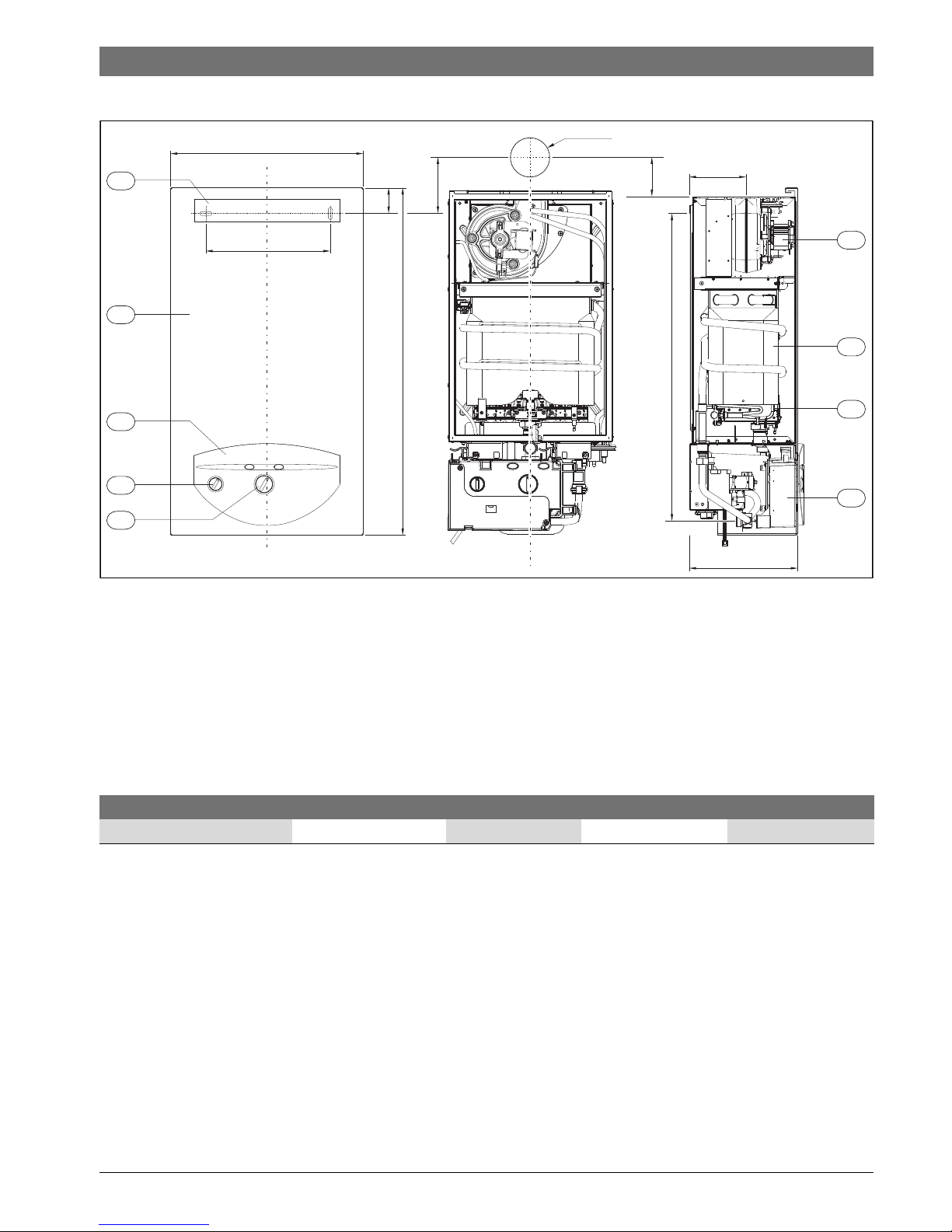
2.6 Dimensions
Fig. 1
[1] Front cover
[2] Mirror
[3] On/off switch
[4] Fan
[5] Heat exchanger
[6] Burner
[7] Control box
[8] Temperature selector
[9] Fixing bracket
1
4
5
6
7
3
8
2
A
B
D
C
6720607298-04.2Av
9
65
90
Ø115
134
230
114
A B C D
WT11 340 670 220 65
Table 4 Dimensions
6 720 607 800 (2016/02)
6 | Appliance specifications
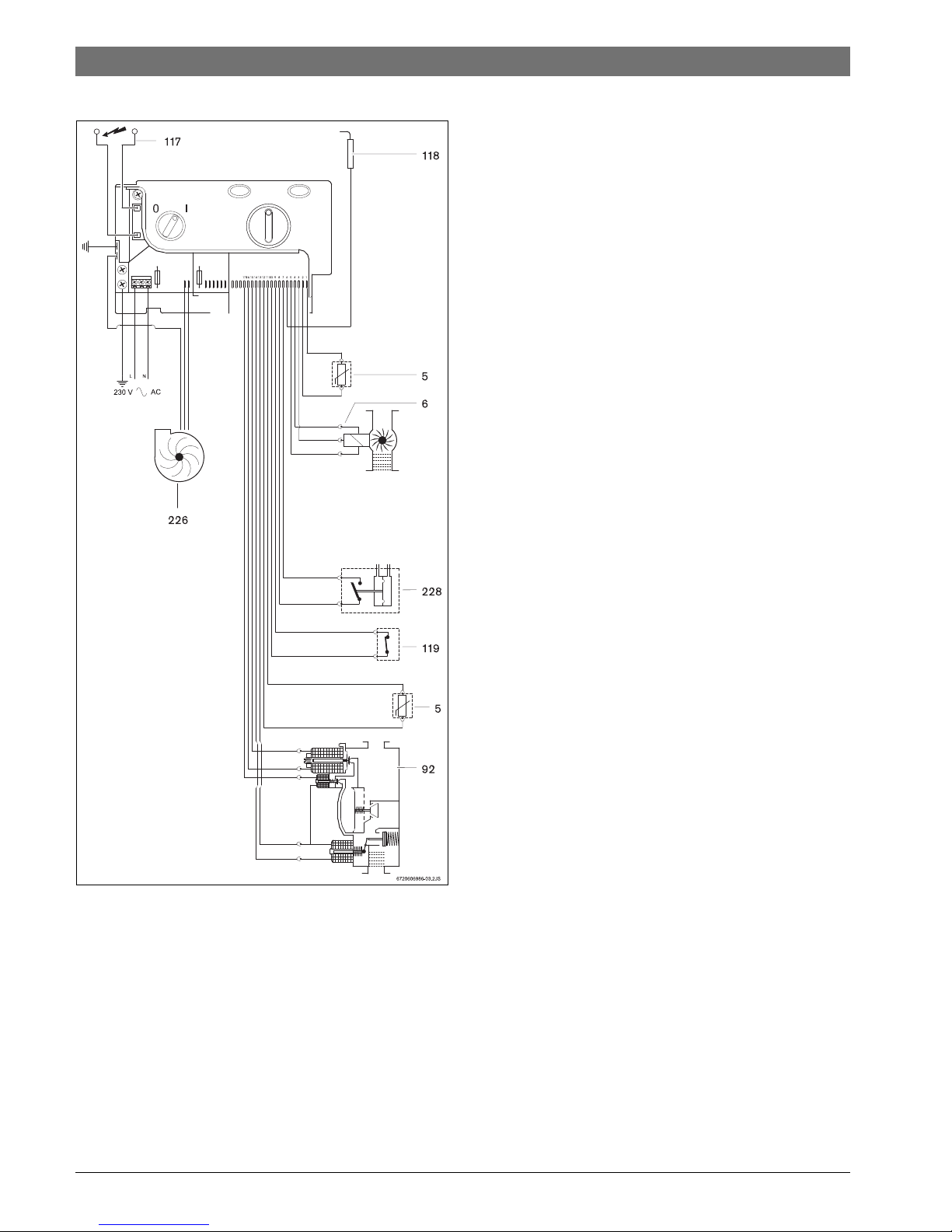
2.7 Electrical layout
Fig. 2 Electrical layout
[5] Heat sensor
[6] Water flow sensor
[92] Gas valve
[117] Ignition electrode
[118] Ionization electrode
[119] Temperature limiter
[226] Fan
[228] Differential pressostat
2.8 Operational instructions
Hot water
Open the gas and water valves and ensure that all joints are
hermetic.
Place the main switch (Fig. 3, [3]) in the operating position
(chapter 3.2), so that the appliance is quickly ready for use.
When a hot tap is opened, the water flow sensor should be in
(Fig. 2, [6]) send a signal to the control unit. This signal
initiates the following:
•The fan starts working
• Simultaneously, sparks are produced and the gas valve
(Fig. 2, [92]) opens.
•The burner lights
• The ionization electrode (Fig. 2, [118]) controls the state
of the flame
• The water temperature is controlled automatically by the
sensors/controllers according to the temperature selected
Security cut-off when safety period is surpassed
If a flame is not achieved within the stipulated security period
(15 sec), a security cut-off will occur.
The presence of air in the gas inlet pipe (when the appliance is
used after long periods of inactivity for example) may delay
ignition.
In this case, if the attempts to ignite go on too long, the security
mechanisms prevent operation.
Security cut-off due to excessive water heating
The control unit detects the heating temperature via a NTC
resistor located in the hot water exit tube and the temperature
limiter located in the heat exchanger. If it detects an excessive
temperature it provokes a security cut-off.
Security cut-off due to deficient exhaust conditions
(pressostat)
The pressostat detects pressure differences outside the fan
and effects a security cut-off when it detects deficient exhaust
conditions.
Restarting after security cut-off
To restart the appliance following a security cut-off:
▶ Press the reset button.
6 720 607 800 (2016/02)
Appliance specifications | 7
2.9 Technical data
Technical characteristics Symbols Units WT11
Power
1)
1) GPL: Butane 45.65 MJ/kg (12.7 kWh/kg) – Propane 46.34 MJ/kg (12.9 kWh/kg)
Usable power Pn kW 19,3
Minimum usable power Pmin kW 7
Regulatory field 7 - 19,3
Nominal power Qn kW 21,8
Minimum nominal power Qmin kW 9
Gas data
Inlet pressure
G.P.L. (Butane/Propane) G30/G31 mbar 28-30/37
Consumption*
G.P.L. (Butane/Propane) G30/G31 kg/h 1,9
Gas connection 3/4”
Water data
Maximum admissible pressure
2)
2) In order to account for the dilation effect of water, it should not exceed this value.
pw bar 12
Minimum working pressure pwmin bar 0,3
Startup flow l/min 3,2
Flow corresponding to a temperature rise of 25 °C l/min 11
Water connection 3/4”
Smoke circuit
Combustion gas flow
3)
3) For nominal calorific power
kg/h 50
Temperature of gases at extractor grill
Using maximum possible drive compression (4 m) °C 170
Using minimum drive compression (0,37 m) °C 220
Flue socket dia. mm Ø60/100
Electrical circuit
Tension (50 HZ) V 230
Maximum power limit W65
Type of protection IPX4D
General Data
Weight (excluding packaging) kg 20
Height mm 670
Width mm 340
Depth mm 220
Table 5
6 720 607 800 (2016/02)
8 | Appliance specifications
2.10 Product data on energy consumption
The following product data complies with the requirements of EU Regulations 811/2013, 812/2013, 813/2013 and 814/2013
as supplement to the Directive 2010/30/EU.
Product data Symbol Unit 7701411040
Product type – – WT 11 AM1 E 31
Emissions of nitrogen oxides NO
x
mg/kWh 171
Sound power level, indoors L
WA
dB(A) 54
Declared load profile – –S
Other load profiles – –M
Water heating energy efficiency class – –A
Water heating energy efficiency
wh
%54
Water heating energy efficiency (other load profiles)
wh
%63
Annual electricity consumption AEC kWh 27
Annual electricity consumption (other load profiles) AEC kWh 35
Daily electricity consumption (average climate conditions) Q
elec
kWh 0,125
Annual fuel consumption AFC GJ 3
Annual fuel consumption (other load profiles) AFC GJ 7
Daily fuel consumption Q
fuel
kWh 3,978
Smart control enabled? – –No
Thermostat temperature (factory setting) T
set
°C –
Table 6 Product data on energy consumption
6 720 607 800 (2016/02)
Use | 9
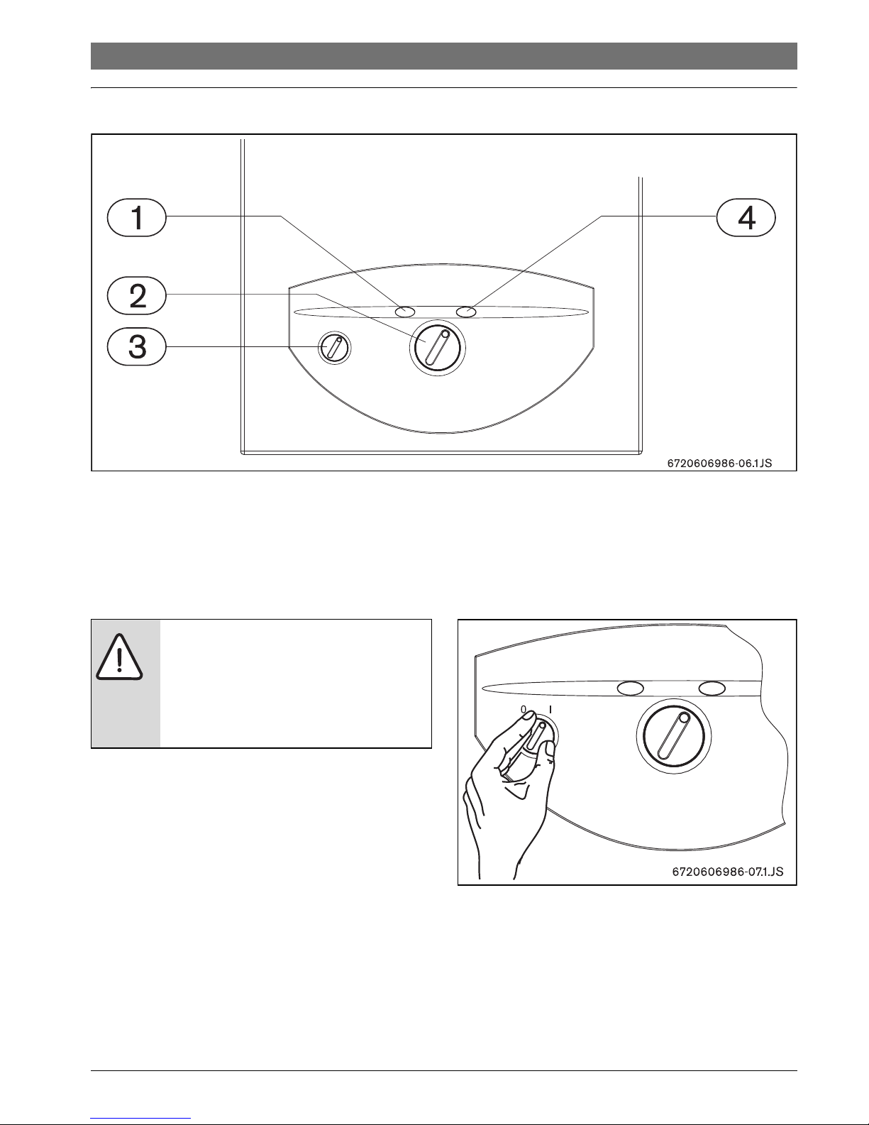
3Use
Fig. 3
[1] Reset button
[2] Temperature selector
[3] Main switch
[4] Burner state key
3.1 Before operating the appliance
▶ Ensure that the type of gas specified on the characteristics
panel is the same as that provided on the site.
▶ Open the gas valve.
▶ Open the water valve.
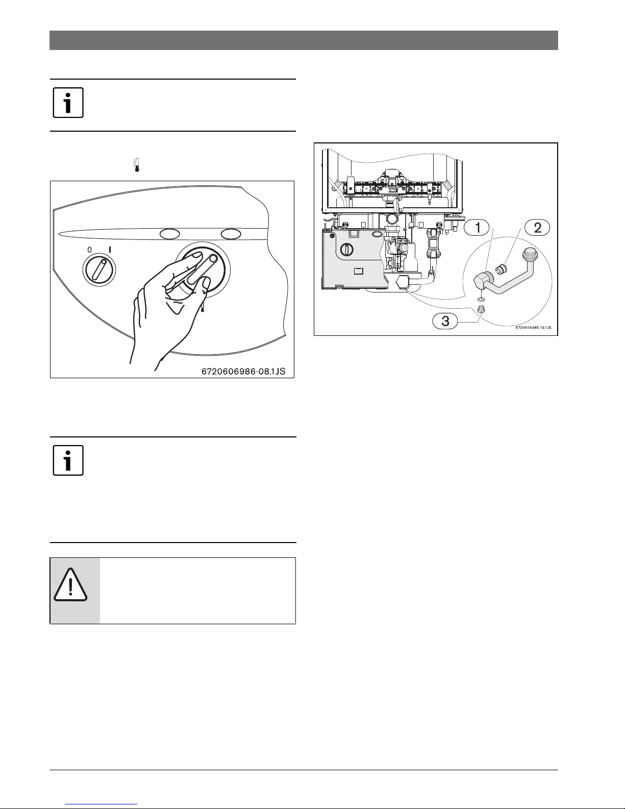
3.2 Connect and disconnect the appliance
Connect
▶ Turn the main switch to position I.
The panel shows the temperature to which the water will be
heated.
Fig. 4
Disconnect
▶ Turn the main switch to position 0.
CAUTION:
▶ The initial startup of the heater must be
realized by a qualified technician, who
will provide the client with all the
information necessary for its correct
usage.
6 720 607 800 (2016/02)
10 | Use
3.3 Regulation of water temperature
To regulate the emitted water temperature:
▶ turn the selector , to the desired value.
Fig. 5
▶ When the desired value has been selected, open the hot
water tap.
3.4 Breakdown indication
The appliance incorporates a breakdown indication system.
Anomalies are detected by the red light on the reset button
(Fig. 3, [1]). The appliance can only be restarted once the
fault has been repaired and the reset button pressed.
To identify the fault consult chapter 10 in this manual.
3.5 Purge appliance
If there is a risk of freezing, proceed as follows:
▶ Loosen the purge screw (Fig. 6) located on the water inlet
pipe.
▶ Empty the appliance of all water.
Fig. 6 Purge screw
The temperature value on the regulator
corresponds to the emission temperature.
If the temperature selected is superior to that
permitted by the power of the appliance, the
water may not achieve the desired
temperature. In this case, the exit flow should
be adjusted:
▶ Close the hot water tap until the desired
value is acquired.
CAUTION:
▶ The area in front of the burner can reach
very high temperatures, and there is a
risk of burning on contact.
6 720 607 800 (2016/02)
Flue accessories | 11
4Flue accessories
4.1 Flue Accessories
Flue pipes have an internal diameter of 60 mm and external
diameter of 100 mm.
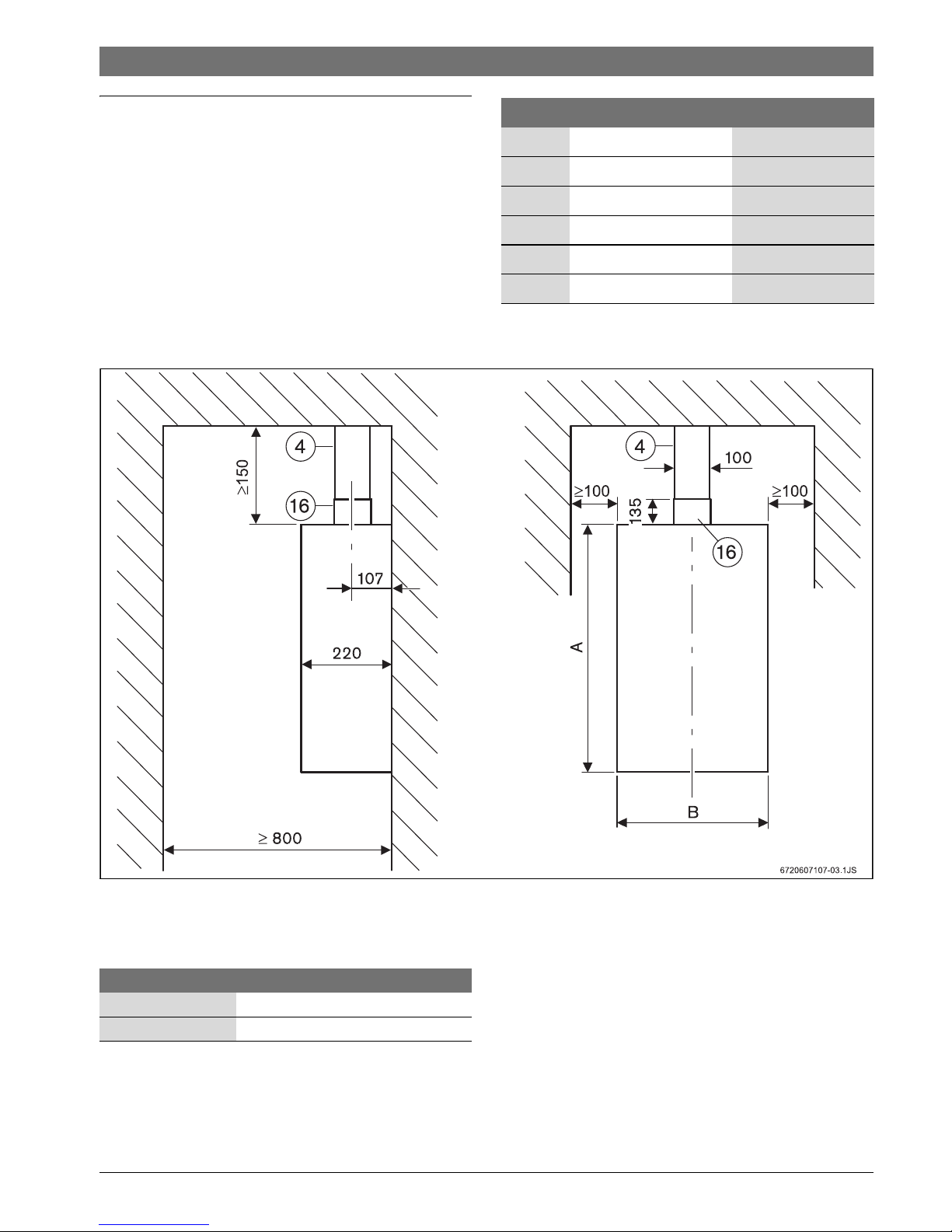
4.1.1 Vertical flue
Fig. 7 Recommended clearance (mm)
[4] AZ 396
[16] Adapter concentric Ø 60/100mm
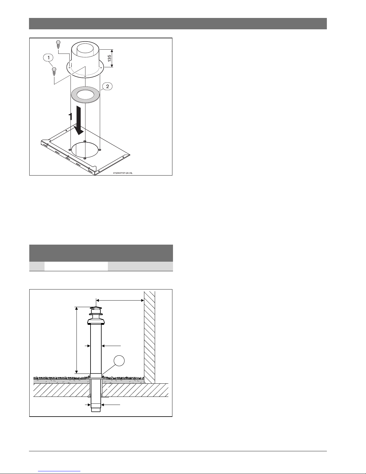
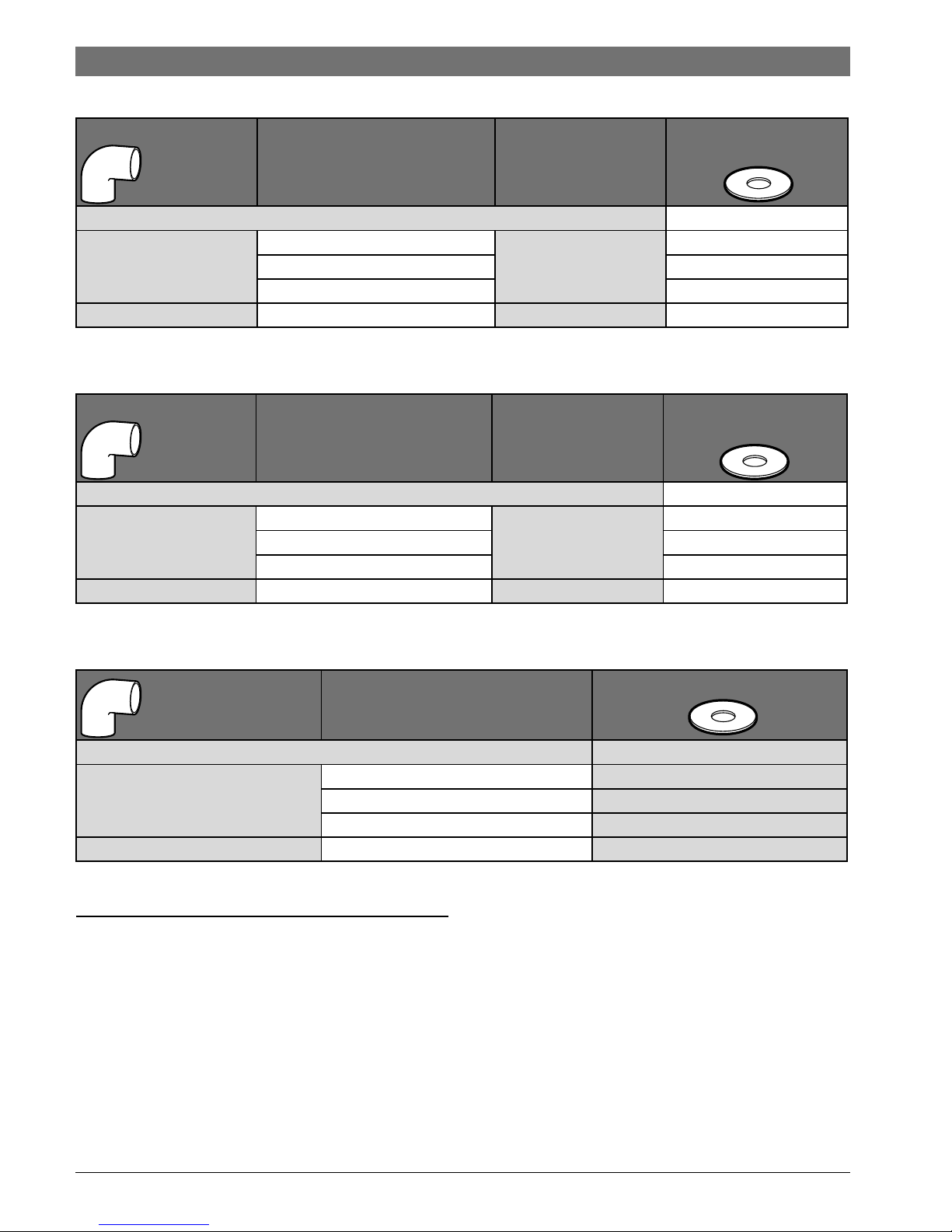
4.1.2 Fitting the restrictor plate
Depending on flue exhaust and installations conditions, a
restrictor plate may need to be fitted (Fig. 8) under the
accessory (table 11 and 12).
In order to assure a good appliance functioning, correct
restrictor plates should be used.
Type Description TTNR
AZ388 Horizontal set 7 716 050 063
--- Flue pipe 350 mm 7 736 995 059
--- Flue pipe 750 mm 7 736 995 063
--- Elbow 45° 7 736 995 071
--- Elbow 90° 7 736 995 079
AZ396 Vertical set 7 716 050 071
Table 7 Flue accessories Ø60-100mm
WT11
A 670
B 340
Table 8
6 720 607 800 (2016/02)
12 | Flue accessories
Fig. 8 Restrictor plate
▶ Loosen accessory fixing screws (Fig. 11, [1]).
▶ Place restrictor plate (Fig. 11, [2]) between the
accessory and the appliance.
▶ Reassemble the accessory in the appliance using the 4
screws (Fig. 11, [1]).
Security distance, flat roof
Fig. 9 Recommended clearance (mm)
inflammable material
no
inflammable material
X 1500 500
Table 9
Ø134
Ø125
X
865
6 702 604 882-02.
17
6 720 607 800 (2016/02)
Flue accessories | 13
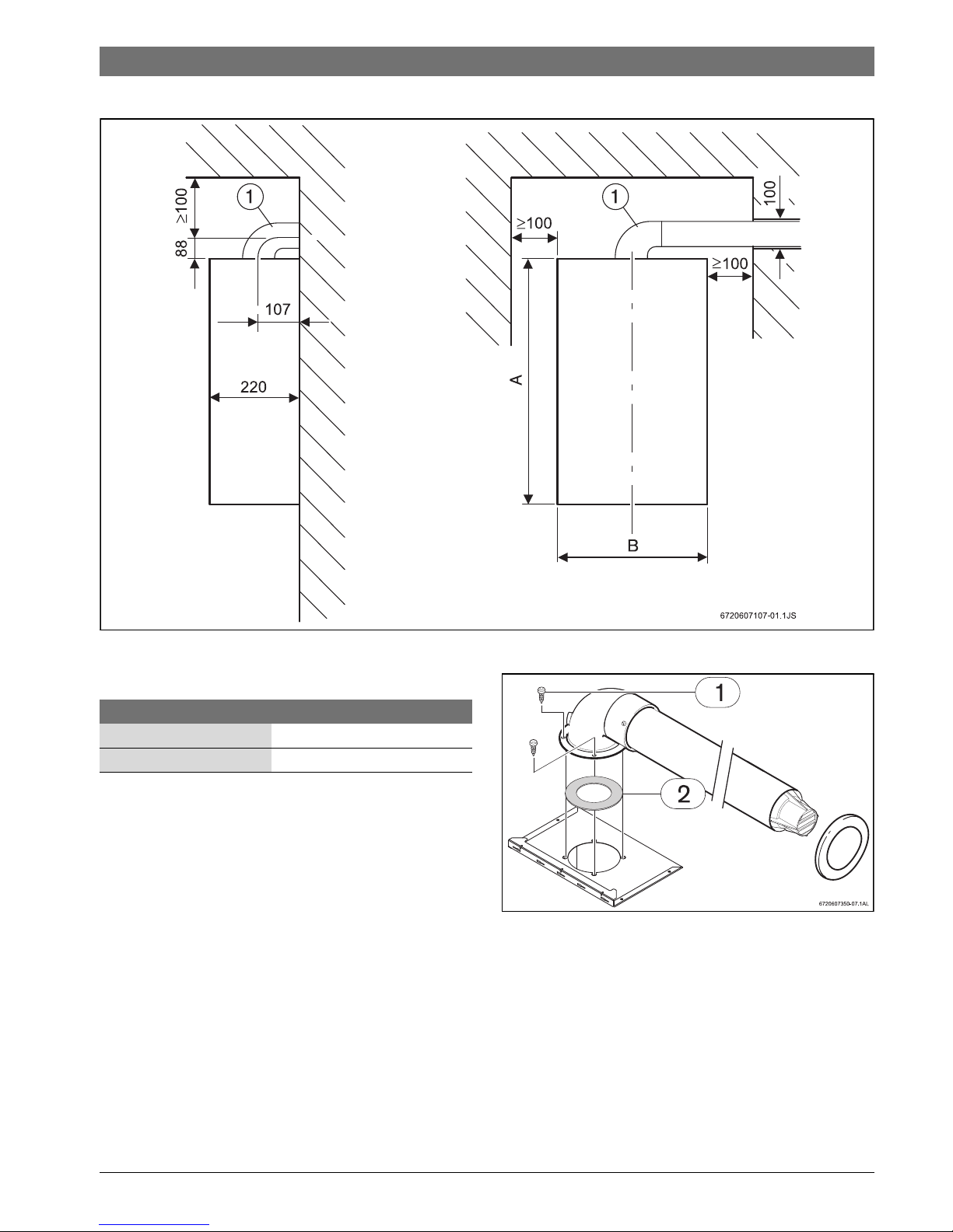
4.1.3 Horizontal flue
Fig. 10 Recommended clearance (mm)
[1] AZ 388
4.1.4 Fitting the restrictor plate
Depending on flue exhaust and installations conditions, a
restrictor plate may need to be fitted (Fig. 11) under the
accessory (table 11 and 12).
In order to assure a good appliance functioning, correct
restrictor plates should be used.
Fig. 11 Restrictor plate
▶ Loosen accessory fixing screws (Fig. 11, [1]).
▶ Place restrictor plate (Fig. 11, [2]) between the accessory
and the appliance.
▶ Reassemble the accessory in the appliance using the 4
screws (Fig. 11, [1]).
WT11
A 670
B 340
Table 10
6 720 607 800 (2016/02)
14 | Regulation
Flue configuration C
12
- horizontal, with accessory AZ388 and 7736995083
Flue configuration C32 - vertical, with accessory AZ396
Flue configuration C52 - max. length for 80/80: 6 m
5Regulation
The currently applicable country standards must be observed.
L
[mm]
L
max
[mm]
WT.11
1 x 90° 1500 4000 Ø 78
1500 - 2500 Ø 78
2500 - 4000 Ø 78
2 x 90° 2000 2000 Ø 86
Table 11
L
[mm]
L
max
[mm]
WT.11
0 x 90° 1850 3850 Ø 76
1850 - 2850 Ø 76
2850 - 3850 Ø 76
2 x 90° 2850 2850 Ø 76
Table 12
L [mm]
WT11
0 x 90° 1850 Ø 76
1850 - 2850
Ø 76
2850 - 6000
Ø 76
2 x 90° 4000 Ø 76
Table 13
90°
90°
90°
6 720 607 800 (2016/02)
Installation | 15
6 Installation
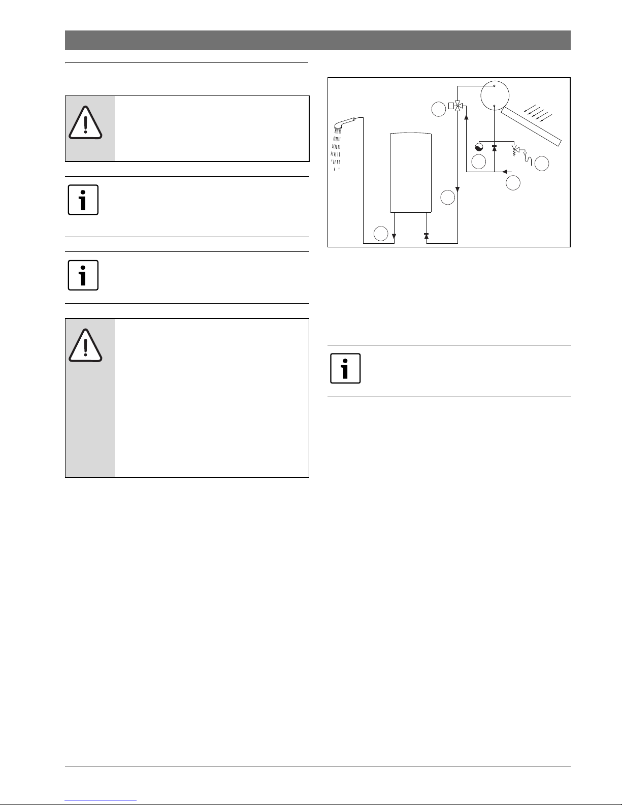
Solar installations
Fig. 12 Solar installation
[1] Cold water
[2] Hot water
[3] Thermostatic valve
[4] Expansion vessel
[5] Safety unit
6.1 Important
▶ Before installation, consult the gas company and current
legislation regarding gas appliance and site ventilation.
▶ Install a gas shut-off tap as close to the appliance as
possible.
▶ After connection to the gas main, the appliance should be
carefully cleaned and tested for leaks; To avoid damage
from excess pressure in the automatic gas regulator, this
should be carried out with the gas valve shut.
▶ Ensure that the appliance installed is suitable for the type
of gas provided.
▶ Ensure that the flow and pressures for the regulator
installed are those indicated for the consumption of the
appliance (see technical data in table 5).
6.2 Selection of location for installation
Considerations relevant to location
▶ Fulfil requirements specific to each country.
▶ The heater must not installed above a source of heat.
▶ Respect the minimum installation measurements indicated
in Fig. 13.
DANGER: Explosion
▶ Always turn off the gas cock before
carrying out any work on components
which carry gas.
Installation, electrical connection, gas
installation, connection of inlet and exhaust
pipes and initial startup must be realized
exclusively by authorized personnel.
The heater can only be used in the countries
indicated on the appliance type plate.
CAUTION: Assure that inlet water into the
appliance does not exceed 60 °C, for
example when used as a backup for solar
installations.
▶ A 3-way valve or thermostatic valve
(adjusted to values lower than 60 °C)
must be installed before the appliance if
inlet water temperature exceeds this
limit.
▶ Assure that the installation contains an
expansion vessel.
For outlet temperature greater then 45 °C we
recommend the use of a descaling system.
2
2
1
3
6720608999-11.6V
T
5
4
 Loading...