

Bosch Worchester GREENSTAR ZWB 7-27 HE combi Installation And Servicing Instructions
Installation and Servicing Instructions
GREENSTAR HE combi
Wall mounted condensing boiler for central heating and mains
fed domestic hot water
6 720 610 577-00.10
ZWB 7-27 HE combi GC-Number: 47 311 55
6 720 610 576 GB (02.05) OSW

Contents
Contents
Safety precautions 3
Symbols 3
1 Details of the appliance 4
1.1 EC Declaration of Conformity 4
1.2 Standard package 4
1.3 Description of appliance 4
1.4 Accessories 5
1.5 Casing dimensions 5
1.6 Layout of appliance 6
1.7 Function 7
1.8 Electrical wiring diagram 8
1.9 Technical data 9
2 Installation regulations 11
3 Installation 11
3.1 Important remarks 11
3.2 Domestic hot water 12
3.3 Sealed systems 12
3.4 Siting the appliance 13
3.5 Wall mounting frame assembly 14
3.6 Pre-piping the system 14
3.7 Fitting the appliance 15
3.8 Checking the connections 16
3.9 Flue Systems 16
3.9.1 Siting the Flue Terminal 17
3.9.2 Installation of the flue 18
3.9.3 Flue duct preparation and assembly 20
4 Electrical connections 21
4.1 Connecting the appliance 21
4.2 Mains Voltage external controls connections 22
5Commissioning 23
5.1 Commissioning 23
5.2 Switching the appliance on/off 24
5.3 Switching on the central heating 24
5.4 System controls 24
5.5 Setting the domestic hot water temperature and flow rate 24
5.5.1 Domestic hot water temperature 24
5.5.2 Hot water flow rate 25
5.6 Summer mode (hot water only) 25
5.7 Frost protection 25
5.8 Pump anti-seize function 25
5.9 Fault Condition 25
6 Individual settings 26
6.1 Mechanical settings 26
6.1.1 Checking the size of the expansion vessel 26
6.1.2 Setting the central heating flow temperature 26
6.1.3 Changing the heating pump characteristic 26
6.2 Settings on the Bosch Heatronic 27
6.2.1 Operating the Bosch Heatronic 27
6.2.2 Selecting the pump control mode for central heating mode (Service Function 2.2) 27
6.2.3 Setting the anti-cycle time (Service Function 2.4) 27
6.2.4 Setting the maxim CH flow temperature (Service Function 2.5) 28
6.2.5 Setting the switching difference (Service Function 2.6) 28
6.2.6 Setting the heating output (Service Function 5.0) 28
6.2.7 Constant hot water cycle time (Service Function 6.8) 28
6.3 Setting the gas/air ratio 28
7 Converting the appliance to different
gas types 29
7.1 Setting the gas/air ratio 29
7.2 Testing combustion air/flue gas at set heat output 31
7.2.1 Testing the O
or CO2 level in the
2
combustion air 31
7.2.2 Testing CO and CO
31
2
8 Maintenance 32
8.1 Pre-Service Check List 33
8.2 Description of servicing operations 34
8.3 Replacement of Parts 38
8.3.1 PCB control board and transformer 38
8.3.2 Fan Assembly 39
8.3.3 Pump 39
8.3.4 3-way diverter valve 40
8.3.5 3-way diverter valve motor 40
8.3.6 Sensors 40
8.3.7 Gas Valve 41
8.3.8 Domestic Hot Water Heat Exchanger 41
8.3.9 Electrode assembly 41
8.3.10Pressure gauge 41
8.3.11Expansion vessel 41
8.3.12Pressure Relief Valve 41
8.3.13Burner 41
8.3.14Flow switch 42
8.3.15Primary Heat Exchanger 42
9Appendix 43
9.1 Fault Codes 43
9.2 Short parts list 44
9.3 Heating/hot water output settings (N.G.) 45
9.4 Heating/hot water output settings (L.P.G) 45
9.5 Operational Flow diagrams 46
9.5.1 Domestic hot water function 46
9.5.2 Central heating function 47
2
6 720 610 576 GB (02.05)

Safety precautions
Safety precautions
If you smell gas
B Turn off gas service cock at the meter.
B Open windows and doors.
B Do not operate any electrical switches.
B Extinguish any naked flames.
B Telephone your gas company.
If you smell fumes from the appliance
B Switch off appliance (see page 24).
B Open windows and doors.
Fitting and modifications
B Fitting of the appliance or any controls to the appli-
ance may only be carried out by a competent engineer in accordance wth the Gas Safety (Installation
and Use) Regulations 1998.
B Flue systems must not be modified in any ways other
than as described in the fitting instructions.
B This appliance is for use on sealed primary systems
only.
Maintenance
B The user is recommended: to have the system
regularly serviced in order to ensure that it functions
reliably and safely.
B Use only original spare parts!
Symbols
Safety instructions in this document
are identified by a warning-triangle symbol and are printed on a grey background.
Notes containing important information
are identified by the symbol shown on the
i
left. They are bordered by horizontal lines
above and below the text.
Combustible materials
B Do not store or use any combustible materials
(paper, thinners, paints etc.) in the vicinity of the
appliance.
Health and safety
B This appliance contains no asbestos products.
B There is no potential hazard due to the appliance
being electrically unsafe.
B There are no substances used in the construction
that are a potential hazard in relation to the COSHH
Regulations (Control of Substances Hazardous to
Health Regulations 1988).
Combustion air/Ambient atmosphere
B The combustion air/ambient atmosphere should be
kept free of chemically aggressive substances (e.g.
halogenated hydrocarbons which contain chlorine or
fluorine compounds). This will prevent corrosion.
Instructions to the customer
B Explain to the customer how the appliance works and
how to operate it.
B Advise the user that he/she must not make any modi-
fications to the appliance or carry out any repairs on it
B These instructions are to be left with the user or at
the Gas meter.
B Important: These instructions apply in the UK only.
6 720 610 576 GB (02.05)
3

Details of the appliance
1 Details of the appliance
1.1 EC Declaration of Conformity
This appliance is in accordance with the applicable
requirements of the Gas Appliance Directive, Boiler Efficiency Directive, Electromagnetic Compatibility Directive and the Low Voltage Directive.
PIN
CE-0085 BL 0507
Category
UK
Appliance Type
II
2H 3P
C
13
, C
33
Table 1
1.2 Standard package
• Gas condensing combination boiler for central heating and domestic hot water
• Wall mounting frame
• Clamp for securing flue duct kit
• Fixings (screws etc.)
• Set of documentation for appliance
• Pre-plumbing manifold
• Condensate drain pipe.
1.3 Description of appliance
• Wall-mounted appliance, siting not dependent on
room size
• Natural gas models are low-emission appliances
• Multifunction display
• Bosch Heatronic control system
• Automatic ignition
• Modulating control
• Full safety systems incorporating Bosch Heatronic
with flame ionisation monitoring, solenoid valves and
temperature sensors
• Concentric flue/air duct with testing point for
/CO
CO
2
• Regulated speed fan
•Pre-mix burner
• Temperature control for central heating
• Temperature sensor in domestic hot water
• Safety temperature limiter in 24 V electrical circuit
• Three-speed central heating pump with automatic
vent
• Relief valve, pressure gauge, expansion vessel
• Flue gas temperature limiter (105 °C)
• Hot water priority circuit
• Motorised 3-way valve
• Plate-type heat exchange
• Condensate Trap.
4
6 720 610 576 GB (02.05)
1.4 Accessories
• Standard horizontal flue kit at 100 mm outside
diameter for flues upto 4 m in length.
• Flue duct kits for horizontal (125 mm outside
diameter) for flue lengths upto 13 m and vertical flue
systems for flue lengths uto 15 m. Fitting instructions
are sent with these kits.
•Heating programmer
•Timer
• Security kit.
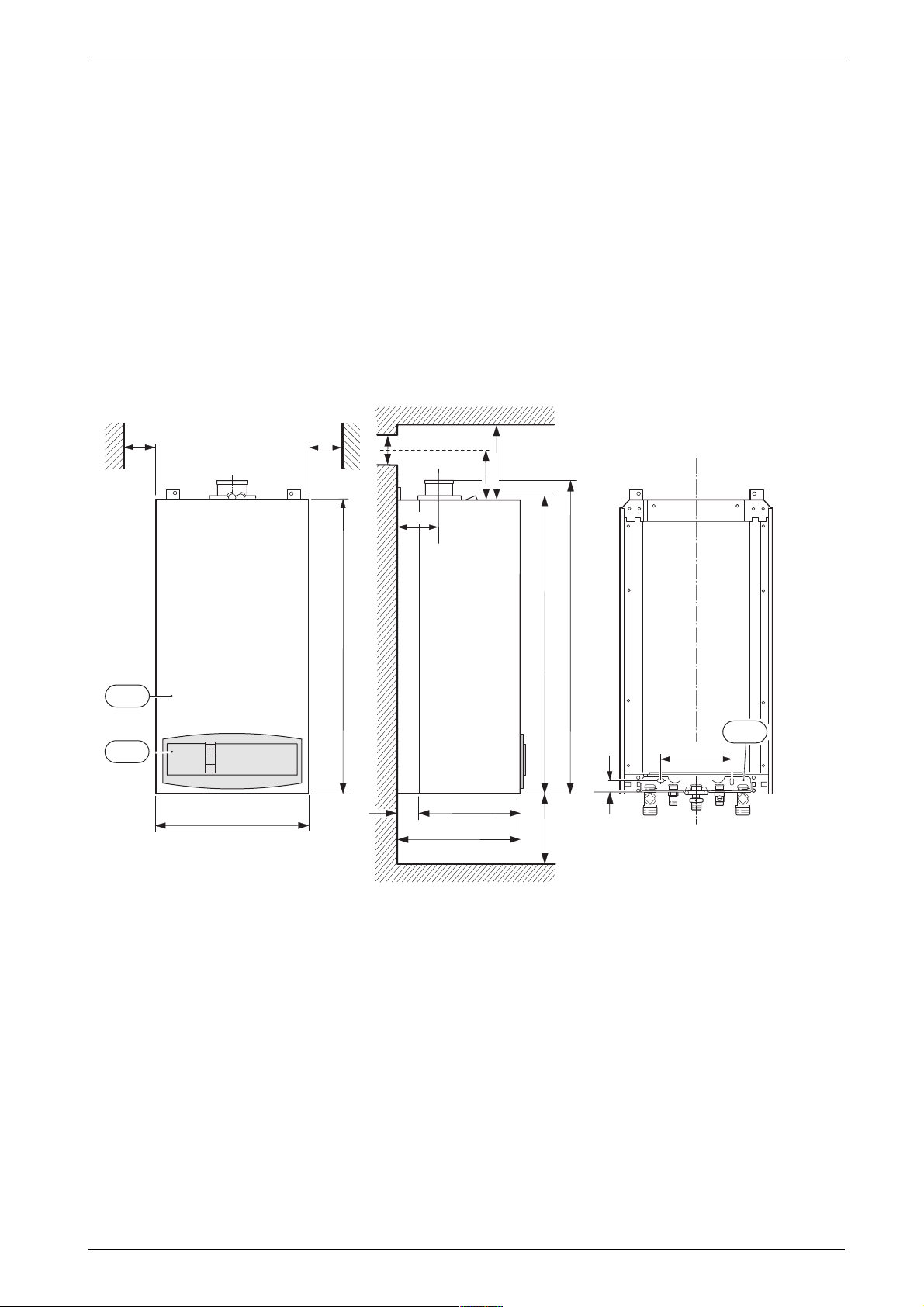
1.5 Casing dimensions
Details of the appliance
min.
101
103
min.
5
5
Z
X
Y
120
850
861
906
13
200
30
440
35
360
395
250
6 720 610 601-01.1O
Fig. 1
13 Manifold assembly
101 Outer case
103 Facia cover
X Standard Concentric Horizontal Flue System: min. 310 mm
Alternative Concentric Flue System: min. 250 mm
Y Standard Concentric Horizontal Flue System: 158 mm
Alternative Concentric Flue System: 121 mm
Z Standard Concentric Horizontal Flue System: 105 mm
Alternative Concentric Flue System: 130 mm
6 720 610 576 GB (02.05)
5

Details of the appliance
1.6 Layout of appliance
221.1
221.2
27
226
20
29
271
43
9
63
120
349
234.1
234
102
32.1
36
6
415
416
358
64
7
355
6.1
295
417
Fig. 2
4 Heatronic control
6 Heat exchanger safety temperature limiter
6.1 Hot water NTC sensor
7 Testing point for gas supply pressure
8.1 Pressure gauge
9 Flue gas temperature limiter
15 Relief valve
18 Pump
18.1 Pump speed selector switch
20 Expansion vessel
27 Automatic air vent
29 Air gas Mixer unit
32.1 Electrode assembly
36 Temperature sensor in CH flow
43 CH flow
63 Adjustable gas flow restrictor
64 Adjusting screw for min. gas flow volume
88 3-way valve (combi)
98 DHW flow switch (combi)
18
423
18.1
418
15
8.1
88
98
4
6 720 610 576-02.2O
102 Inspection window
120 Fixing points
221.1 Flue duct
221.2 Combustion air intake
226 Fan assembly
295 Appliance type sticker
234 Testing point for combustion products
234.1 Testing point for combustion air
271 Flue duct
349 Cover plate for twin flue duct connection
355 Plate-type domestic hot water heat exchanger
358 Condensate trap
415 Cover plate for cleaning access
416 Condensate collector
417 Clip for fixing outer case
418 Data plate
423 Siphon
6
6 720 610 576 GB (02.05)
1.7 Function
Details of the appliance
Fig. 3
4 Bosch Heatronic control
6 Temperature limiter, heat exchanger
6.1 Hot water NTC sensor
7 Testing point for gas supply pressure
8.1 Pressure gauge
9 Flue gas temperature limiter
13 Manifold
15 Safety valve
18 Central heating pump
20 Expansion vessel
26 Charging valve
27 Automatic vent
29 Mixer unit
29.1 Bi-metallic thermostat for combustion air compensation
30 Burner
32 Flame sensing electrode
33 Igniter electrode
35 Heat exchanger with cooled combustion chamber
36 Temperature sensor in CH flow
43 CH flow
44 Hot water flow
45 Gas inlet
46 Cold water inlet
47 CH return
52 Solenoid valve 1
52.1 Solenoid valve 2
55 Filter
56 Gas valve CE 427
57 Main valve disc
61 Reset button
63 Adjustable gas flow restrictor
64 Adjusting screw for min. gas inlet flow volume
69 Control valve
84 Motor
88 3-way valve
90 Venturi
91 Pressure relief valve
93 Water flow regulator
94 Diaphragm
95 Pushrod with switch cam
96 Microswitch
97 Valve for hot water flow volume
98 Water valve
221 Flue duct
226 Fan
229 Inner casing
234 Testing point for flue gas
234.1 Testing point for combustion air
317 Display
355 Plate-type heat exchanger
358 Condensate trap
423 Siphon
443 Diaphragm
6 720 610 576 GB (02.05)
7
Details of the appliance
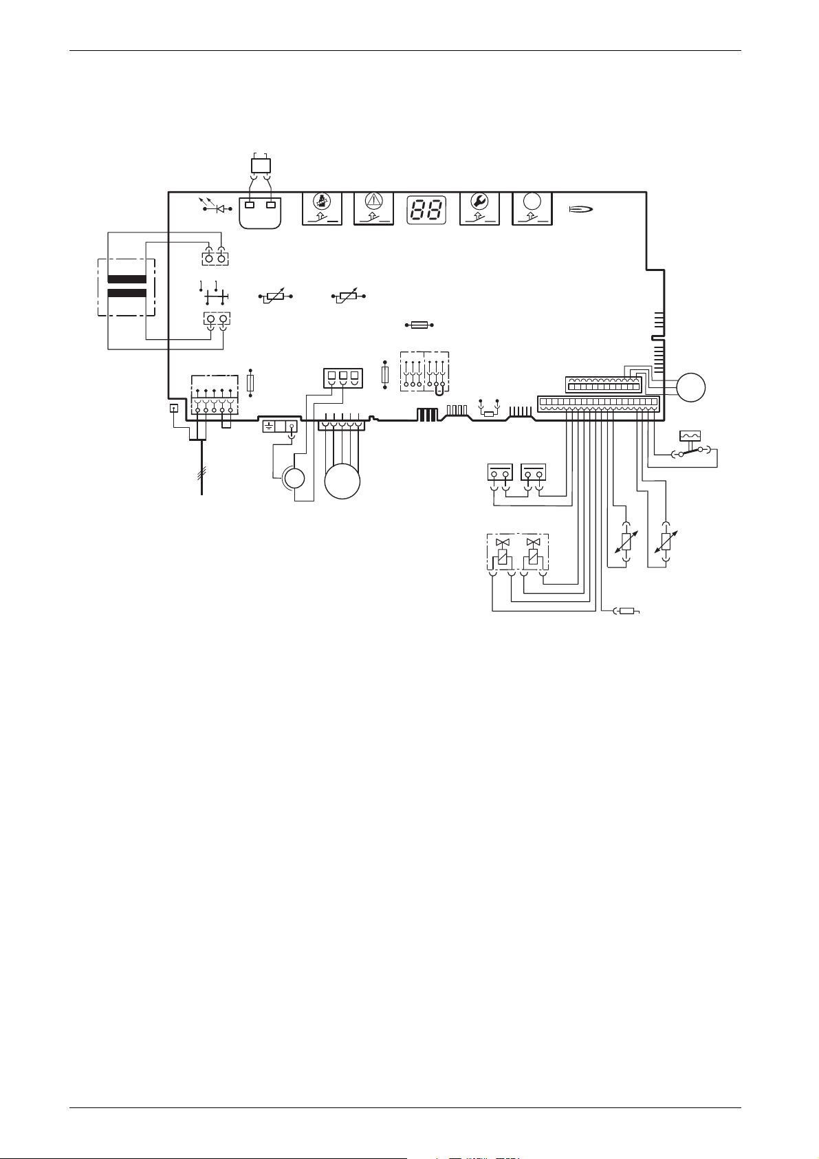
1.8 Electrical wiring diagram
33
364
4.1
o - orange g - green bl - black r - red p - purple
365
61
317
366
367
ECO
363
25 V
153
230V/AC
135
302
230 V
328
L
Ns
NLs
136
151
LR
328.1
mains supply
Fig. 4
4.1 Ignition transformer
6 Temperature limiter, heat exchanger
6.1 Hot water NTC sensor
9 Flue gas temperature limiter
18 Pump
32 Flame sensing electrode
33 Ignition electrode
36 Temperature sensor in CH flow
52 Solenoid valve 1
52.1 Solenoid valve 2
56 Gas valve CE 427
61 Reset button
84 Motor, 3-way valve
96 Microswitch, hydraulic switch
135 Master switch
136 Temperature control for CH flow
151 Fuse, slow 2.5 A, AC 230 V
153 Transformer
M
18
310
M
226
313
312
315
89
1247
300
9
52
314
6
52.1
r
r
161
56
bl
bl
bl
bl
161 Link
226 Fan
300 Code plug
302 Earth connection
310 Temperature control for hot water
312 Fuse, slow T 1,6 A
313 Fuse, slow T 0,5 A
314 Connector for programmer
315 Terminal block for programmer
317 Digital display
318 Connector for timer
328 Terminal block for AC 230 V Mains supply
328.1 Link
363 Indicator lamp for burner
364 Indicator lamp for power supply
365 “Chimney sweep” button
366 Service button
367 ECO button
bl
6 720 610 576-08.2O
318
84
p
p
M
p
96
g
g
o
o
o
o
36
6.1
32
8
6 720 610 576 GB (02.05)
Details of the appliance
1.9 Technical data
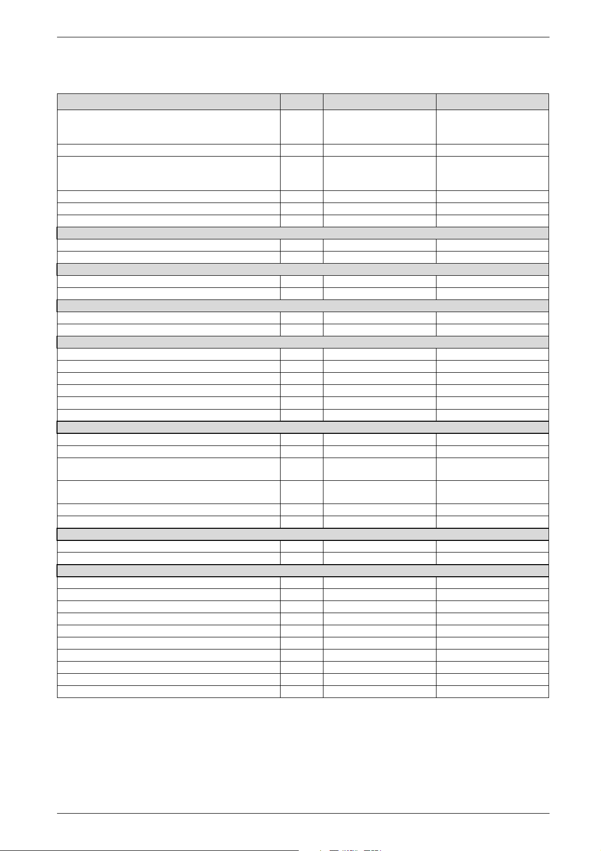
Units Natural gas Propane
Max. rated heat output net 40/30°C central heating
Max. rated heat output net 50/30°C central heating
Max. rated heat output net 80/60°C central heating
Max. rated heat input net kW 27.5 27.5
Min. rated heat output net 40/30°C
Min. rated heat output net 50/30°C
Min. rated heat output net 80/60°C
Min. rated heat input net kW 7.6 10.8
Max. rated heat output net, domestic hot water kW 27.2 27.2
Max. rated heat input net, domestic hot water kW 27.5 27.5
Maximum gas flow rate – After 10 minutes from lighting
Natural gas G20 (H
LPG (H
= 12,9 kWh/kg) kg/h - 2.1
i
= 9,5 kWh/m3)m
is
Gas supply pressure
Natural gas G20 mbar 20 LPG mbar - 37
Expansion vessel
Charge pressure bar 0.75 0.75
Total capacity l 10 10
Hot water specifications
Hot water flow rate (factory setting) l/min 8 8
Max. hot water flow rate l/min 14 14
Outlet temperature range °C 40 - 60 40 - 60
Max. permissible water supply pressure bar 10 10
Min. inlet pressure bar 0.2 0.2
Specific flow rate l/min 12.4 12.4
Flue
Flue gas temp. 80/60°C, rated/min. load °C 67/55 67/55
Flue gas temp. 40/30°C, rated/min. load °C 43/32 43/32
Residual delivery pressure
(inc. pressure drop in air intake duct) Pa 80 80
CO
level at max. rated heat output
2
level at min. rated heat output
CO
2
NO
-class 5 5
x
SEDBUK figure, Band A % 90.6 90.6
Condensate
Max. condensation rate (t
= 30°C) l/h 2.3 2.3
R
pH-value, approx. 4.8 4.8
General Data
Electrical power supply voltage AC ... V 230 230
Frequency Hz 50 50
Max. power consumption W 101 101
Noise output level dB(A) 36 36
Appliance protection rating IP X4D X4D
Max. CH flow temperature °C nom. 90 nom. 90
Max. permissible operating pressure (CH) bar 2.5 2.5
Permissible ambient temperatures °C 0 - 60 0 - 60
Nominal capacity of appliance l 3.75 3.75
Weight (excluding packing) kg 46 46
Table 2
kW
kW
kW
kW
kW
kW
3
/h 2.9 -
%
%
29.1
28.8
27.2
8.4
8.3
7.4
9.5
9.2
29.1
28.8
27.2
11.6
11.4
10.5
11.3
11.0
6 720 610 576 GB (02.05)
9
Details of the appliance
Condensate analysis, mg/l
Ammonium 1.2 Nickel 0.15
Lead ≤ 0.01 Mercury ≤ 0.0001
Cadmium ≤ 0.001 Sulphate 1
Chromium ≤ 0.005 Zinc ≤ 0.015
Halogenated
hydrocarbons ≤ 0.002
Hydrocarbons 0.015 Vanadium ≤ 0.001
Copper 0.028 pH-value 4.8
Tin ≤ 0.01
Table 3
Flue system
HORIZONTAL 100 mm – Standard
Overall Diameter of Duct mm 100
Flue Terminal / Duct Assembly Length
Extension Duct Length mm 1000
mm 750
Max.
4m
Table 4
ALTERNATIVE HORIZONTAL 125 mm FLUE SYSTEM
Overall Diameter of Duct mm 125
Flue Terminal / Duct Assembly mm 550
Extension Duct Length - Fixed mm 200
Extension Duct Length - Fixed mm 450
Extension Duct Length - Fixed mm 950
Extension Duct Length - Fixed mm 1950
Extension Duct Length Telescopic
Extension Duct Length - Adjustable (Cut to length)
mm 265-
375
mm 200
Table 5
Max.
13 m
(including
turret)
VERTICAL 125 mm FLUE SYSTEM
Overall Diameter of Duct mm 125
Flue Terminal / Duct Assembly mm 1360
Extension Duct Length mm 200
Extension Duct Length - Fixed mm 450
Extension Duct Length - Fixed mm 950
Extension Duct Length - Fixed mm 1950
Extension Duct Length - Telescopic
Extension Duct Length Adjustable (Cut to length)
mm 265-
375
mm 450
Table 6
Elbow - 90 ° Bend - 45 °
Equivalent length 2 m Equivalent length 1m
Gas supply
Total length of gas supply pipe
(metres)
369
Gas discharge rate (m
8.7 5.8 4.6 22
18.0 12.0 9. 4 28
3
/h)
Pipe diameter
(mm)
Table 7
Domestic water performance
Temperature
Rise
Domestic
Water Flow
Rate l/min
Maximum Mains pressure bar 10.0
Temperature
Rise
Temperature
Rise
30 °C 13.2
35 °C 11.3
40 °C 9.9
Max.
15 m
10
Minimum Mains pressure bar 0.2
Table 8
6 720 610 576 GB (02.05)

Installation regulations
2 Installation regulations
Gas Safety (Installation & Use) Regulations 1998: All
gas appliances must be installed by a competent person. Failure to install correctly could lead to prosecution.
The manufacturers notes must not be taken, in any way,
as overriding statutory obligations.
The appliance must be installed in accordance with the
current IEE Wiring Regulations, local Building Regulations, Building Standards (Scotland) (Consolidation),
bye-laws of the local Water Company, Health and
Safety Document 635 (Electricity at Work Regulations
1989) and any other local requirements.
Product Liability regulations indicate that, in certain circumstances, the installer can be held responsible, not
only for mistakes on his part but also for damage resulting from the use of faulty materials. We advise the
installer to avoid any risk by using only quality approved
branded fittings.
The relevant British Standards should be followed i.e.
• BS 6798: Specification for the installation of gas
fired hot water boilers of rated input not exceeding
60kW
• BS 5449: Central Heating for Domestic Premises
• BS 5546: Installation of gas hot water supplies for
domestic purposes
• BS 5440:1: Flues and ventilation for gas appliances
of rated input not exceeding 70 kW (gross): Flues
• BS 5440:2: Flues and ventilation for gas appliances
of rated input not exceeding 60 kW (gross): Air
Supply
• BS 6891: Installation of low pressure gas pipework
installations up to 28mm (R1).
• BS 7074:1: Code of practice for domestic heating
and hot water supply.
3 Installation
B Always turn off the gas cock before car-
rying out any work on components
which carry gas.
Fixing of the appliance, gas and flue connections, commissioning of the system
i
and electrical connections may only be
carried out by competent persons authorised by CORGI.
3.1 Important remarks
B Appliance should only be installed in sealed central
heating systems.
B To avoid gas formation in the system, galvanised radi-
ators or pipes must not be used.
B If a room thermostat is used: do not fit a thermostatic
radiator valve on the radiator in the primary room.
B Add a suitable anti-freeze fluid compatible with alu-
minium to the water in the central heating system.
Suitable products are available from Betz-Dearborn
Tel.: 0151 4209563 and Fernox Tel.: 01799
550811.
B In our experience, the addition of sealing agents to
the water in the central heating system can cause
problems (deposits in the heat exchanger). For that
reason we advise against their use.
These instructions must be followed.
6 720 610 576 GB (02.05)
11

Installation
3.2 Domestic hot water
Any regulations specified by the local water company
must be observed.
The final 600 mm of the mains cold water connection to
the applaince should be made in copper tube only.
The appliance is suitable for a mains supply having a
ma xim u m p ressure of 10 bar. A p r e ssure reducing valv e
must be fitted, if necessary.
The hot water outlet temperature is set to be capable of
achieving a maximum of 60 °C. The maximum temperature and the frequency of the recharge of the heat store
may be reset.
The maximum water flow rate is factory set at 9.9 l/min
to give temperature rise of 40 °C. If a higher rise is
required then the flow must be reduced at the tap and
the discharge temperature will rise up to the maximum
set figure.
The temperature rise, upto the maximum set by the user,
is automatically maintained by the modulation of the
heat input. In winter, when the mains temperature is very
low, the water flow, adjusted at the tap or shower,
should be reduced to maintain the required delivery
temperature.
It is suggested that long pipe runs to taps or showers
be insulated to prevent the rapid cooling of the water.
All types of single lever mixer taps and thermostatic
mixer units suitable for a mains pressure of up to 10 bar
can be used.
The head of a loose-head shower must not be allowed
to fall within 25 mm of the top the bath to prevent the
risk of water being drawn back into the mains. Alternatively the shower must be fitted with an anti-syphonage
device at the point of the flexible hose connections.
Over-rim bidets may be connected to the appliance provided that it is in accordance with the requirements of
the local water company. The outlet(s) should be
shrouded and unable to have any temporary hand held
spray attached. No anti-syphonage arrangements are
necessary.
In exceptionally hard water areas a device to prevent
scale formation may be fitted or, alternatively, the maximum temperature reset to about 45 °C which may
reduce the risk of scale formation. The installation of a
scale inhibitor assembly should be in accordance with
the requirements of the local water company. Artificially
softened water must not be used to fill the central heating system. An isolating valve should be fitted to allow
for servicing.
Devices, such as water meters or back-flow prevention valves, capable of preventing the flow of expansion water must not be fitted unless separate
arrangements have been made.
A Zilmet Z160 expansion vessel is the preferred type. A
thread sealant compatible with potable water must be
used.
3.3 Sealed systems
The appliance must not be operated without the system
being full of water, properly vented and pressurised.
The expansion vessel has a volume of 10 litres and is
charged to a pressure of 0.75 bar.
The water capacity of the system is shown in table 11,
page 26. If a greater capacity is required then an additional expansion vessel must be fitted into the system
return as clo s e t o t he applia n c e a s p ossibl e . Th e s ystem
pressure can be set up to a maximum of 1.5 bar with 1
bar being the normal setting.
If the system pressure is greater than 2.65 bar when the
appliance is operating at maximum temperature then an
additional expansion vessel must be fitted into the system return as close to the appliance as possible.
The filling point must be at low level and arranged as
shown in figs. 5 and 6.
The pressure relief valve is set to operate at 3 bar.
There must be no connection to the mains without the
approval of the local water company. All connections in
the system must be capable of withstanding a pressure
of up to 3 bar and the radiator valves conform to the
requirements of BS 2767:10.
If Thermostatic Radiator Valves are fitted then it is recommended that one radiator is left open.
Repeated venting probably indicates a leak and this
must be rectified to ensure the proper operation of the
appliance.
No galvanised radiators or pipes must be used.
If any system water treatment is required then only
products suitable for use with Aluminium shall be
used i.e Fernox- Copal or Sentinal X100, in
accordance with the manufacturers instructions.
The use of any other substances will invalidate the
guarantee. The pH value of the system water must
be less than 8 or the appliance guarantee will be
invalidated.
A drain cock to BS2879 must be fitted to the lowest
point of the system.
IMPORTANT: Check that no dirt is left in the water
pipework as this could damage the appliance.
Thoroughly flush the heating system and the mains
water supply before fitting the appliance to the wall
in accordance with the recommendations of
BS7593:1992.
12
6 720 610 576 GB (02.05)
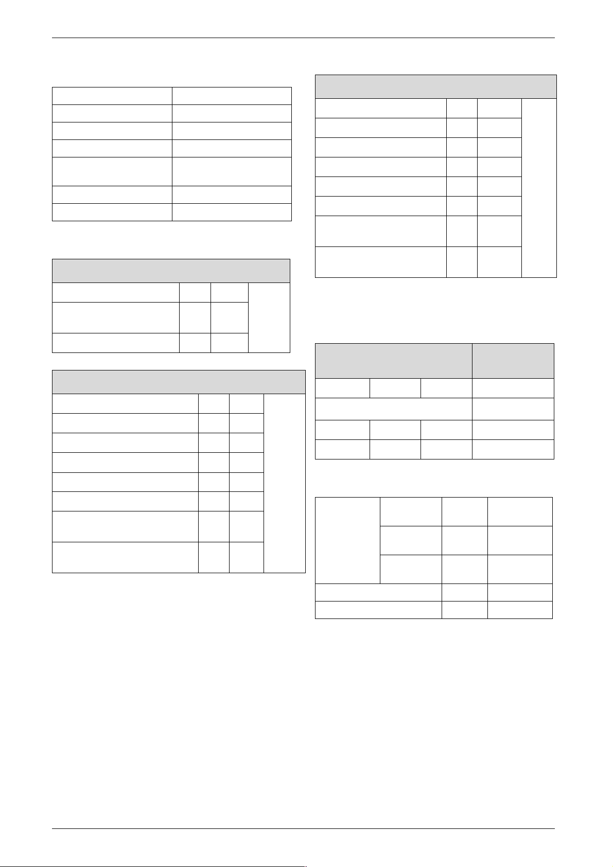
APPLIANCE
Refer to Fig.1
Appliance
water flow
diagram
WRC approved
filling loop
Central heating return
Domestic
hot water
Central heating flow
BS stop valve.
Fixed spindle type
Water
main
Fig. 5 Sealed primary water system
A drain cock should be fitted at
the lowest point of the heating
circuit and the appliance
Radiator
valve
6 720 610 576 -09.2O
Lockshield
valve
Installation
Heating
return
Non-return
valve
Non-return
valve
Test
cock
Fig. 6 Sealed primary water system - filling method
3.4 Siting the appliance
Regulations concerning the Installation Site
B Relevant national regulations must be complied with
section 3.9.1.
B Consult the installation instructions for details of min-
imum clearances required.
Combustion air
In order to prevent corrosion, the combustion air must
not contain any corrosive substances.
Substances classed as corrosion-promoting include
halogenated hydrocarbons which contain chlorine and
fluorine compounds and are contained in some solvents, paints, adhesives, aerosol propellants and household cleaners, for example.
Hose
union
Temporary hose
Hose
union
Test
cock
6 720 610 576 - 10.1O
Surface temperature
The max. surface temperature of the casing and the flue
is less than 85 °C.
This means that, no special safety precautions are
required with regard to flammable building materials
and fitted furniture. The specified clearences must be
maintained.
Cupboard/Compartment
The appliance can be installed in a cupboard/compartment need for airing clothes providing that the requireme nt s o f BS6798 and BS544 0: 2 are followed. Th e low
casing losses from the appliance eliminate the need for
ventilation openings in the compartment.
6 720 610 576 GB (02.05)
13
Installation
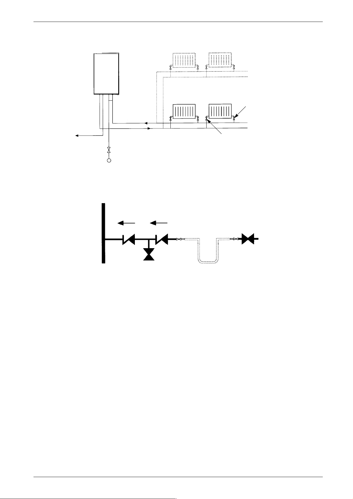
3.5 Wall mounting frame assembly
B Take the wall mounting frame out of the package and
screw together with 6 screws as shown in fig. 7. Use
the inner lugs on the top and bottom horizontal
sections for the appliances that are 440 mm wide.
6 720 610 576-04.1O
Fig. 7
B Hold the wall-mounting frame against the wall
ensuring that it is vertical.
B Mark the position of the flue duct hole if a rear flue is
to be used. Refer to fig. 1 and 15.
B Mark the holes for the wall mounting frame onto the
wall, drill and plug the holes and screw the wall
mounting frame to the wall with the screws provided.
B Screw the pre-plumbing manifold with two screws to
the wall mounting frame.
6 720 610 576-11.1O
Fig. 9
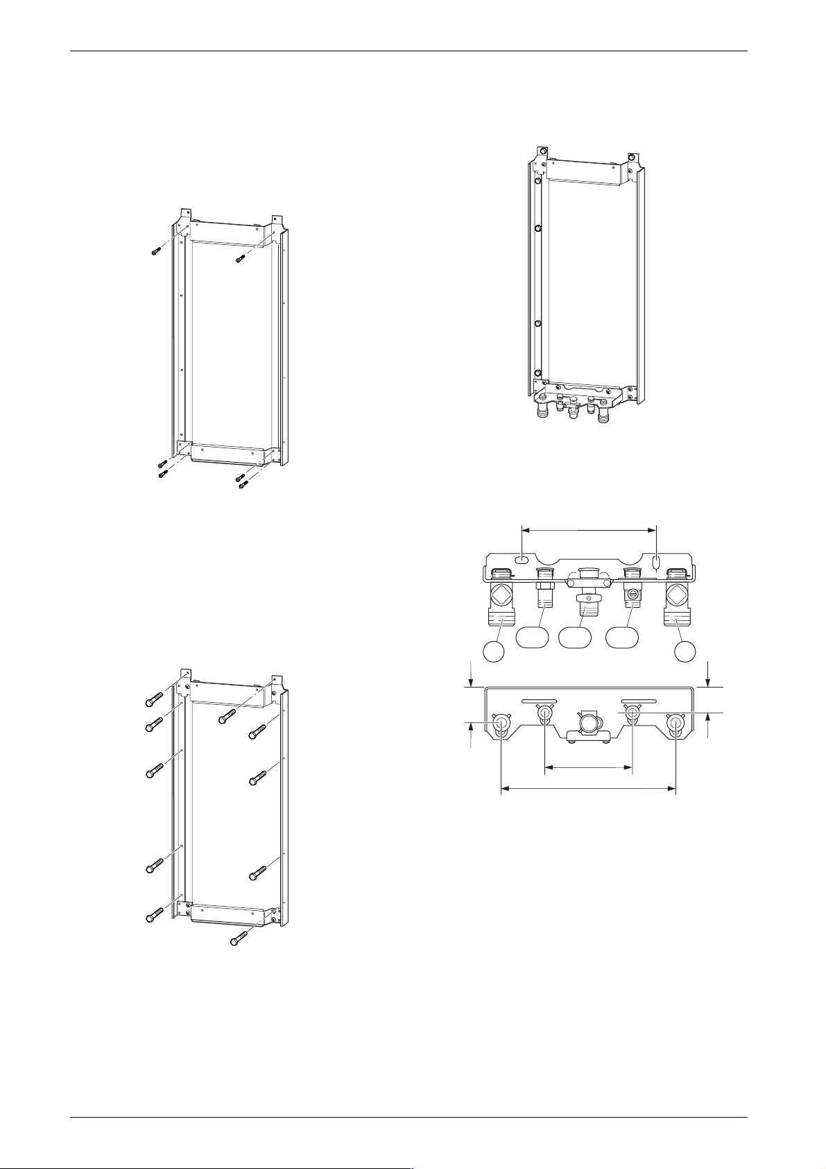
3.6 Pre-piping the system
200
171
172112
4743
Fig. 8
6 720 610 576-05.1O
50
35
120-130
260
6 720 610 576-06.1O
Fig. 10 Manifold
43 CH flow
47 CH return
112 Gas cock
171 Domestic hot water
172 Cold water relief
B A drain tap should be fitted at the lowest point of the
central heating system.
B WRc filling loop must be fitted.
14
6 720 610 576 GB (02.05)

Installation
Condensate drain
Prepare the condensate discharge system. Refer to
fig. 11. The condensate drainage pipe should be a
standard drain pipe material , i . e. PVC, PVC-U, ABS
etc. and should be at least 22 mm in diameter.
A siphon with a 75 mm condensate seal is fitted within
the appliance.
A connection to an internal drain is recommended.
Any external drain pipe should be insulated to prevent
freezing.
The connection of a condensate pipe to a drain may be
subject to local building regulations.
For more information refer to the CIBSE Guide,
BS5546 and the Building Regulations.
3.7 Fitting the appliance
Benchmark: For optimum performance
after installation, this boiler and its associated central heating system must be
flushed in accordance with the guidelines given in BS5793:1992 “Treatment
of water in domestic hot water central
heating systems”.
B Remove packing, taking care to observe the instruc-
tions on the packing.
B Lie the boiler on its back.
Removing the outer case
The outer case is secured against unauthorised removal by two clips (electrical
i
safety).
Always secure the outer case with those
clips again after refitting.
B Turn the clips with a screwdriver (1.).
B Slide the outer case upwards and then forwards to
remove (2.).
B Remove the plastic caps from the boiler connections.
Fig. 11 Position of the condensate drain
2.
1.
6 720 610 602 - 03.1O
6 720 610 332-07.1R
Fig. 12
Fixing the appliance
B Fit the washers onto the gas and water connections.
B Lift the boiler onto the wall-mounting frame. The lugs
pass through the rectangular holes in the boiler bac k
panel.
B Take care not to disturb the washers on the connec-
tions.
6 720 610 576 GB (02.05)
15
 Loading...