

Bosch WORCESTER GREENSTAR WIRING CENTRE Installation, Commissioning & Servicing Instructions
INSTALLATION COMMISSIONING & SERVICING INSTRUCTIONS
GREENSTAR WIRING CENTRE
60
0
5
4
3
2
1
I
70
0
4
max
S
off
I
I
Y0
6 720 801 106-00.1O
6 720 804 107 (2012/10) en
CONTENTS
CONTENTS
1 Key to symbols and safety instructions . . . . . . . . . . . . . . . . . . . 2
1.1 Key to symbols . . . . . . . . . . . . . . . . . . . . . . . . . . . . . . . . . . 2
1.2 Safety instructions . . . . . . . . . . . . . . . . . . . . . . . . . . . . . . 2
2 Product details . . . . . . . . . . . . . . . . . . . . . . . . . . . . . . . . . . . . . . . . 2
2.1 Correct use . . . . . . . . . . . . . . . . . . . . . . . . . . . . . . . . . . . . 3
2.2 Standard delivery . . . . . . . . . . . . . . . . . . . . . . . . . . . . . . . 3
2.3 Specification . . . . . . . . . . . . . . . . . . . . . . . . . . . . . . . . . . . 3
2.4 Cleaning and care . . . . . . . . . . . . . . . . . . . . . . . . . . . . . . . 4
2.5 Additional system components . . . . . . . . . . . . . . . . . . . . 4
3 Installation . . . . . . . . . . . . . . . . . . . . . . . . . . . . . . . . . . . . . . . . . . . 4
3.1 Installation . . . . . . . . . . . . . . . . . . . . . . . . . . . . . . . . . . . . . 4
3.2 Electrical connections . . . . . . . . . . . . . . . . . . . . . . . . . . . . 5
3.2.1 Connection of BUS and temperature sensor ( 24 V) . . 5
3.2.2 Connection to mains power, pump and
valves (230 V AC) . . . . . . . . . . . . . . . . . . . . . . . . . . . . . . . 5
3.2.3 Wiring diagrams with system examples . . . . . . . . . . . . . . 8
4 Commissioning . . . . . . . . . . . . . . . . . . . . . . . . . . . . . . . . . . . . . 13
5 Troubleshooting . . . . . . . . . . . . . . . . . . . . . . . . . . . . . . . . . . . . 13
5.1 Status indicator . . . . . . . . . . . . . . . . . . . . . . . . . . . . . . . 13
5.2 Replacing the fuse . . . . . . . . . . . . . . . . . . . . . . . . . . . . . 13
6 Environment / disposal . . . . . . . . . . . . . . . . . . . . . . . . . . . . . . . 14
1 KEY TO SYMBOLS AND SAFETY
INSTRUCTIONS
ADDITIONAL SYMBOLS
Symbol Explanation
▶ Step in an action sequence
Cross-reference to another part of the document
• List entry
– List entry (second level)
Table 1
1.2 SAFETY INSTRUCTIONS
▶ Observe all country-specific regulations and standards during
installation and operation.
▶ Observe all instructions to ensure satisfactory operation.
▶ This product must only be installed and commissioned by a
competent person.
▶ Never install this product in wet rooms.
▶ Install and commission the boiler and other accessories according to
the relevant instructions.
▶ Risk of scalding! A mixer device must be installed if water
temperatures higher than 60 °C are set.
▶ Use this product exclusively in conjunction with the Worcester
controls accessory and boilers that comply with the intended use.
Follow the wiring diagram.
▶ The product requires different voltages.
Do not connect the low-voltage equipment to 230 V mains and vice-
versa.
▶ Before installing the product: electrically isolate the boiler and system
components. Secure against unintentional reconnection and make
sure the power supply is disconnected.
ABOUT THESE INSTRUCTIONS
These installation instructions contain important information regarding
the safe and proper installation, commissioning and maintenance of the
product.
These installation instructions are intended for competent persons who,
as a result of their training and experience, are skilled in dealing with
electrical installations and heating systems.
In these instructions the Greenstar Wiring Center will be referred as
“module”.
1.1 KEY TO SYMBOLS
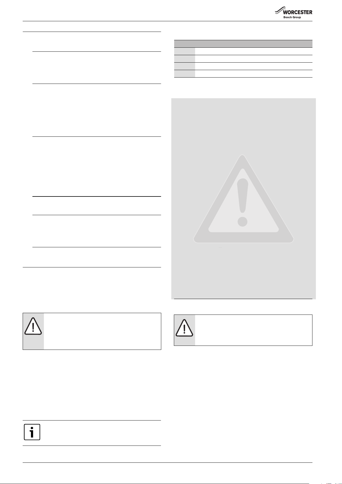
WARNINGS
Warnings in this document are identified by a warning
triangle printed against a grey background.
Keywords at the start of a warning indicate the type and
seriousness of the ensuing risk if measures to prevent
the risk are not taken.
The following keywords are defined and can be used in this document:
• NOTE indicates a situation that could result in damage to property or
equipment.
• CAUTION indicates a situation that could result in minor to medium
injury.
• WARNING indicates a situation that could result in severe injury or
death.
• DANGER indicates a situation that will result in severe injury or death.
IMPORTANT INFORMATION
This symbol indicates important information where
there is no risk to people or property.
2 PRODUCT DETAILS
NOTICE: Floor damage!
▶ Underfloor heating installations must include a
suitable controls package to prevent excessive flow
temperatures entering the floor.
• The module controls the pump and motorized valves in
– a mid-position (Y-plan) system
-or-
– a two-port valve (S-plan) system
-or-
– three central heating circuits only, without electronic mixing valves
-or-
– two central heating circuits without electronic mixing valves and
one domestic hot water cylinder circuit.
• The module collects
– the temperature of the DHW cylinder via the cylinder temperature
sensor supplied
– the demand signals (from room and/or frost thermostats
optionally).
6 720 804 107 (2012/10)2
PRODUCT DETAILS
i
• Pump seizure protection function:
– The connected pump is monitored and ran for a short period after
24 hours of downtime. This prevents the pump from seizing.
A maximum of three modules per system are permissible, irrespective of
the number of other BUS subscribers:
• a maximum of two modules for a total of six heating circuits without
electronic mixing valves
• a maximum of one module for two additional heating circuits without
electronic mixing valves and one cylinder charging circuit
As delivered, the code switch is set to Y. The module will therefore
operate the system as a mid-position (Y-plan). S (S-plan) or other
configurations can be selected when necessary.
2.1 CORRECT USE
The module communicates via an EMS-plus interface with other EMSplus-enabled BUS subscribers such as Greenstar boilers.
▶ Only use the appliance for its intended purpose.
▶ Observe all country-specific regulations and standards during
installation and operation.
2.2 STANDARD DELIVERY
1
5
2
2.3 SPECIFICATION
Design and operation of this product conform to European
Directives and the supplementary national requirements. Its
conformity is demonstrated by the CE designation.
Technical data
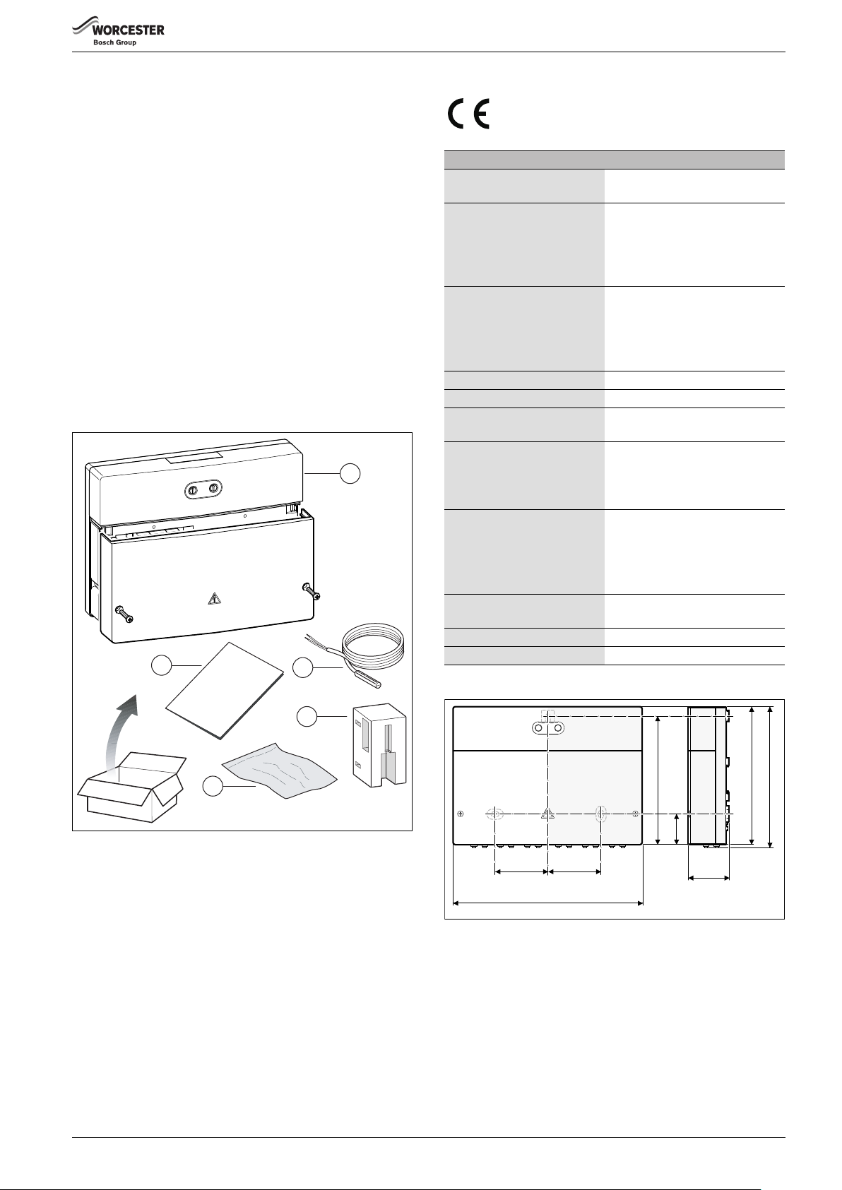
Dimensions (W × H × D) 151 × 184 × 61 mm
(further dimensions fig. 2)
Maximum conductor crosssection
• Terminal 230 V
• Extra-low voltage connecting
terminal
Rated voltages
• BUS
• Module power supply
• Pump and mixer
Fuse 230 V, 5 AT
BUS interface EMS plus
Power consumption –
Standby
max. power output
• per connection (PZ1 ... PZ3)
• per connection (IZ1 ... IZ4)
Temperature sensor
measuring range
• lower fault limit
• display range
• upper fault limit
Permissible ambient
temperature
IP rating IP 44
Id. no. Type plate ( fig. 3, page 4)
Table 2 Technical data
• 2.5 mm
• 1.5 mm
• 15 V DC
• 230 V AC, 50 Hz
• 230 V AC, 50 Hz
< 1 W
• 400 W (high-efficiency pumps
• 230 V AC, max. 0.5 A
• < – 10 °C
• 0 ... 100 °C
• > 125 °C
0 ... 60 °C
2
2
(reverse-polarity-protected)
permissible; max. 40 A/s)
3
4
6 720 804 106-01.1O
Fig. 1 Scope of supply
[1] Module
[2] Cylinder temperature sensor (TC1)
[3] Cylinder temperature sensor (TC1) retaining device. To enable
satisfactory installation of the cylinder temperature sensor on hot
water cylinders without sensor pockets.
[4] Bag with installation material
[5] Installation instructions
72
Fig. 2 Dimensions
246
72
169
40,5
181
61
6 720 804 106-02.1O
184
6 720 804 107 (2012/10) 3
INSTALLATION
60
50
70
4
40
3
2
xo
ma
S
f
f
1
I
I
Y
0
I
6 720 804 106-03.1O
Fig. 3 Position of type plate
Test values for the cylinder temperature sensor (included with the
product)
°C °C
20 14772 56 3723
26 11500 62 3032
32 9043 68 2488
38 7174 74 2053
44 5730 80 1704
50 4608 86 1421
Table 3 Resistance vales of supplied cylinder temperature sensor.
2.4 CLEANING AND CARE
▶ If required, wipe the enclosure with a damp cloth. Never use
chemically aggressive or acidic cleaning agents.
2.5 ADDITIONAL SYSTEM COMPONENTS
• For a mid-position (Y-plan) system:
– Circulating pump; connection to PZ3
– Mid-position valve; connection to PZ1 and PZ2
– Room and/or frost thermostats (optional); connection to IZ3 and
IZ4
• For a two-port valve (S-plan) system:
– Circulating pump; connection to PZ3
– 2 x 2-port valves (with end switches); connection to PZ1 and IZ1
and to PZ2 and IZ2
– Room and/or frost thermostat (optional); connection to IZ3 and IZ4
• For heating circuits with separate heating pumps without electronic
mixing valves (e.g. downstream of low-loss header):
– Circulating pump; connection to PZ1...3
– Room thermostat (optional); connection to IZ1...3
• For domestic hot water cylinder charging circuit with separate
cylinder primary pump (e.g. downstream of low-loss header):
– Cylinder primary pump; connection to PZ1
– Cylinder temperature sensor; connection to TC1
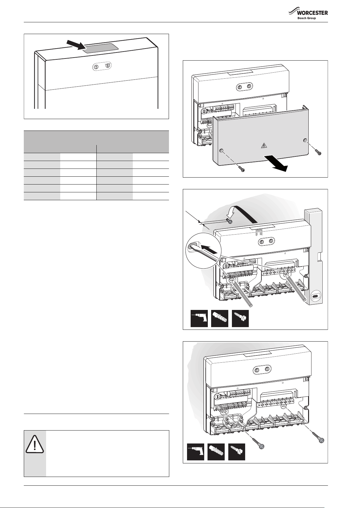
3.1 INSTALLATION
WALL MOUNTING
▶ Mount the module to a wall ( Fig. 4 to 6).
Fig. 4 Wall mounting - step 1
3.
~ 1,5
2.*
1.
4.
*
6 mm 3,5 mm6 mm
Fig. 5 Wall mounting - step 2
6 720 804 106-04.1O
4.
4.
6 720 804 106-05.1O
INSTALLATION OF ADDITIONAL SYSTEM COMPONENTS
▶ Fit additional system components according to legal requirements
and the installation instructions provided.
3 INSTALLATION
DANGER: Risk of electric shock!
▶ Prior to the installation of this product:
Isolate the boiler and system components from the
power supply (230 V AC).
▶ Before commissioning:
Fit the cover ( Fig. 19, page 8).
6 mm 3,5 mm6 mm
Fig. 6 Wall mounting - step 3
6 720 804 106-06.1o
6 720 804 107 (2012/10)4

INSTALLATION
DIN RAIL MOUNTING
▶ Mount the module to a DIN rail ( fig. 7).
6 720 804 106-07.1O
Fig. 7 DIN rail mounting
▶ Observe fig. 8 when removing the component from the DIN rail.
2.
3.2.1 CONNECTION OF BUS AND TEMPERATURE SENSOR
(24 V)
If the maximum cable length of the BUS connections
between all BUS subscribers is exceeded or if the BUS
system is realised as a ring structure, the system cannot
be commissioned.
Maximum total length of BUS connections:
• 100 m at 0.50 mm
• 300 m at 1.50 mm
2
conductor cross-section
2
conductor cross-section
▶ All LV leads must be routed separately from cables carrying mains
voltage to avoid inductive interference (minimum separation
100 mm).
▶ In the case of inductive external interference (e.g. by PV systems), use
shielded cables (e.g. LiYCY) and earth the shield on one side. Do not
connect the shield to the grounded terminal of the module, but to a
building ground terminal, e.g. a free ground terminal or a water pipe.
▶ Connect 1 pair of BUS terminals (BUS 1 and BUS 2) to the BUS
terminals of the boiler.
▶ Connect the cylinder temperature sensor supplied to the terminal
TC1.
For hot water cylinders without sensor pockets, use the
cylinder sensor retaining device to mount the cylinder
temperature sensor securely to the side of the cylinder.
Fig. 8 Removal from DIN rail
3.2 ELECTRICAL CONNECTIONS
DANGER: Risk of electric shock!
▶ Secure together the wires of every cable connected.
This can be done by stripping a short section of cable
sheath or with cable ties close to the terminals
( fig. 9).
3.
1.
6 720 804 106-08.1O
When sensor leads are extended, apply the following lead crosssections:
• Up to 20 m with 0.75 mm
• 20 m up to 100 m with 1.50 mm
2
to 1.50 mm2 conductor cross-section
2
conductor cross-section
▶ Route cables through the grommets provided and connect them as
described in chapter 3.2.3.
3.2.2 CONNECTION TO MAINS POWER, PUMP AND VALVES (230 V AC)
The connection to mains power, pump and valves may
differ depending on the system installed. The following
description is a suggestion how to carry out the electrical
connection of the module.
DANGER: Risk of electric shock!
If the heating system is wired in such a way that the
Greenstar wiring centre and boiler have separate points
of isolation ( fig. 10, page 6):
▶ Attach a warning label to each point of isolation. This
label has to advise that it is not the sole point of
isolation and it has to identify the location of the other
means of isolation.
▶ Electrically isolate the boiler and system
components. Secure against unintentional
reconnection and make sure the power supply is
disconnected.
6 720 647 922-40.1O
Fig. 9 Secure together the wires of every cable connected.
▶ Observe current regulations applicable to power connections, and
use at least cable type H05 VV-…
6 720 804 107 (2012/10) 5
 Loading...