

Bosch Worcester GREENSTAR 12i, Worcester GREENSTAR 24i System System Instruction Manual
THE APPLIANCE IS FOR USE WITH
NATURAL GAS OR L.P.G. (Cat II 2H3P TYPE C13 & C33)
NATURAL GAS:
WORCESTER GREENSTAR 12i System GC NUMBER 41-311-67
WORCESTER GREENSTAR 24i System GC NUMBER 41-311-68
LIQUID PETROLEUM GAS:
WORCESTER GREENSTAR 12i System GC NUMBER 41-311-69
WORCESTER GREENSTAR 24i System GC NUMBER 41-311-70
GB/IE

WORCESTER BOSCH:
TECHNICAL: 08705 266241
SERVIC E: 08457 256206
SPARES: 01905 752571
LITERATURE: 01905 752556
TRAINING: 01905 752526
SALES: 01905 752640
WEBSITE: www.worcester-bosch.co.uk
WATER TREATMENT:
FERNOX 01799 550811
www.fernox.com
SENTINEL 0151 420 9595
www.betzdearborn.com/sentinel
FLUE TERMINAL GUARD:
TOWER FLUE COMPONENTS
VALE RISE
TON BRIDG E
TN9 1TB
PLEASE READ THESE INSTRUCTIONS CAREFULLY BEFORE STARTING INSTALLATION.
THESE INSTRUCTIONS ARE APPLICABLE TO THE WORCESTER BOSCH APPLIANCE
MODEL(S) STATED ON THE FRONT COVER OF THIS MANUAL ONLY AND MUST NOT BE
USED WITH ANY OTHER MAKE OR MODEL OF APPLIANCE.
THE INSTRUCTIONS APPLY IN THE UK ONLY AND MUST BE FOLLOWED EXCEPT FOR ANY
STATUTORY OBLIGATION.
THIS APPLIANCE MUST BE INSTALLED BY A COMPETENT PERSON. FAILURE TO INSTALL
CORRECTLY COULD LEAD TO PROSECUTION.
IF YOU ARE IN ANY DOUBT CONTACT THE WORCESTER BOSCH TECHNICAL HELPLINE.
DISTANCE LEARNING AND TRAINING COURSES ARE AVAILABLE FROM WORCESTER
BOSCH.
PLEASE LEAVE THESE INSTRUCTIONS, THE USER GUIDE AND THE COMPLETED
BENCHMARK CHECKLIST OR A CERTIFICATE CONFIRMING COMPLIANCE WITH IS 813
(EIRE ONLY) WITH THE USER OR AT THE GAS METER AFTER INSTALLATION OR
SERVICING.
ABBREVIATIONS USED IN THIS MANUAL:
Ø Diameter
NG Natural Gas
LPG Liquid Petroleum Gas
CH Central Heating
DHW Domestic Hot Water
IP Ingress Protection
SEDBUK Seasonal Efficiency of Domestic Boilers in the United Kingdom
CONTACT INFORMATION INSTALLATION & SERVICING INSTRUCTIONS
SYMBOLS USED IN THIS MANUAL:
LIFTING AND CARRYING PRECAUTIONS:
• Lift only a manageable weight, or ask for
help.
• When lifting the boiler, bend the knees,
and keep the back straight and feet apart.
• Do not lift and twist at the same time.
• Lift and carry the boiler close to the body
• Wear protective clothing and gloves to
protect from any sharp edges
INSTALLATION &
SERVICING INSTRUCTIONS
INSTALLATION & SERVICING INSTRUCTIONS FOR WORCESTER BOSCH GREENSTAR 12i System/24i System
8 716 107 375a (02/05)
1
STORE THE APPLIANCE IN A DRY
AREA PRIOR TO INSTALLATION.

SAFETY & REGULATIONS
SAFETY PRECAUTIONS & SYMBOLS 3
INSTALLATION REGULATIONS 3
APPLIANCE INFORMATION
GENERAL INFORMATION 4
TECHNICAL DATA 5
LAYOUT & COMPONENTS 6-7
PRE-INSTALLATION
CLEANING PRIMARY SYSTEMS 8
MAINS SUPPLY 9
WATER SYSTEMS & PIPEWORK 10
CONDENSATE PIPEWORK 11
PRESSURE RELIEF PIPEWORK 12
BOILER LOCATION & CLEARANCES 13-14
PLUMBING MANIFOLD 15
FLUE TERMINAL POSITIONS 16
FLUE OPTIONS 17
INSTALLATION
UNPACKING THE WALL FRAME 18
WALL MOUNTING TEMPLATE / FLUE OPENING 19
UNPACKING THE APPLIANCE 20
BOILER CONNECTIONS 21-22
FLUE INSTALLATION 23-25
CONDENSATE CONNECTION 26
ELECTRICAL 27
POSITION OF WIRED COMPONENTS 28
COMMISSIONING
PRE-COMMISSIONING CHECKS 29
FILLING THE SYSTEM 30
STARTING THE APPLIANCE 31
WATER TREATMENT 32
COMMISSIONING 33
FINISHING COMMISSIONING 34
SERVICING & SPARES
INSPECTION AND SERVICE 35-40
REPLACEM ENT OF PARTS 41-50
SETTING THE GAS /AIR RATIO 51
SHORT PARTS LIST 52
CONVERSION KITS
L.P.G. CONVERSION 53-54
FAULT FINDING & DIAGNOSIS
FAULT FINDING 55
CH FUNCTION 56
PROTECTION FUNCTION 57
ADDITIONAL INSTRUCTIONS FOR FITTING OPTIONAL DIVERTER VALVE CAN BE
FOUND AT THE REAR OF THIS MANUAL
CONTENTS
CONTENTS
INSTALLATION & SERVICING INSTRUCTIONS FOR WORCESTER BOSCH GREENSTAR 12i System/24i System
8 716 107 375a (02/05)
2
SAFETY &
REGULATIONS
APPLIANCE
INFORMATION
PRE -
INSTALLATION
INSTALLATIONCOMMISSIONING
SERVICING
& SPARES
CONVERSION
KITS
FAULT FINDING
& DIAGRAMS
SAFETY PRECAUTIONS INSTALLATION REGULATIONS
IF YOU SMELL GAS:
✗ DON’T SMOKE OR STRIKE MATCHES
✗ DON’T TURN ELECTRICAL SWITCHES ON OR OFF
✓ DO PUT OUT NAKED FLAMES
✓ DO OPEN DOORS AND WINDOWS
✓ DO KEEP PEOPLE AWAY FROM THE AREA AFFECTED
✓ DO TURN OFF THE CONTROL VALVE AT THE METER
✓ DO CALL YOUR GAS COMPANY
A Benchmark Checklist is provided by the manufacturer for the installer to complete
including their CORGI registration number to confirm that the boiler has been installed,
commissioned and serviced according to the manufacturer’s instructions.
IMPORTANT: The completed Benchmark Checklist will be required in the event of any
warranty work and may be required by the local Building Control Inspector.
HEALTH & SAFETY
The appliance contains no asbestos and no substances have been used in the
construction process that contravene the COSHH Regulations (Control of Substances
Hazardous to Health Regulations 1988).
COMBUSTIBLE AND CORROSIVE MATERIALS
Do not store or use any combustible materials (paper, thinners, paints etc.) inside or
within the vicinity of the appliance.
Chemically aggressive substances, such as halogenated hydrocarbons containing
chlorine or fluorine compounds can corrode the appliance and invalidate any warranty.
FITTING & MODIFICATIONS
Fitting the appliance and any controls to the appliance may only be carried out by a
competent engineer in accordance with the Gas Safety (Installation and Use)
Regulations 1998.
Flue systems must not be modified in any way other than as described in the fitting
instructions. Any misuse or unauthorised modifications to the appliance, flue or
associated components and systems could invalidate the warranty. The manufacturer
accepts no liability arising from any such actions, excluding statutory rights.
SERVICING
Advise the user to have the system serviced annually by a competent, qualified
engineer (such as British Gas or CORGI registered personnel) using approved spares,
to help maintain the economy, safety and reliability of the appliance.
IMPORTANT - The service engineer must complete the Service Record on the
Benchmark Checklist after each service.
Gas Safety (Installation & Use) Regulations 1998:
All gas appliances must be installed by a
competent person in accordance with the above
regulations. Failure to install appliances correctly
could lead to prosecution.
The appliance must be installed in accordance
with, and comply to, the current: Gas Safety
Regulations, IEE Regulations, Building
Regulations, Building Standards (Scotland)
(Consolidation), Building Regulations (Northern
Ireland), local water by-laws, Health & Safety
Document 635 (The Electricity at Work
Regulations 1989) and any other local
requirements.
British Standards:
The relevant British Standards should be followed,
including:
BS7074:1 : Code of practice for domestic and hot
water supply
BS6891 : Installation of low pressure gas
pipework up to 28mm (R1)
BS5546 : Installation of gas hot water supplies for
domestic purposes
EN:12828 : Central heating for domestic premises
BS5440:1 : Flues and ventilation for gas appliances of rated heating not exceeding 70kW (net) :
Flues
BS5440:2 : Flues and ventilation for gas appliances of rated heating not exceeding 70kW (net) :
Air Supply
BS7593 : Treatment of water in domestic hot
water central heating systems
BS 6798 : Installation of gas fired boilers of rated
input up to 70kW (net)
Where no specific instruction is given, reference
should be made to the relevant British Standard
codes of Practice.
L.P.G. Installation:
An appliance using L.P.G. must not be installed in
a room or internal space below ground level unless
one side of the building is open to the ground.
Timber framed buildings:
Where the boiler is to be fitted to a timber framed
building the guidelines laid down in BS5440: Part
1 and IGE "Gas Installations in Timber Frame
Buildings” should be adhered to.
Potable water:
All seals, joints and compounds (including flux and
solder) and components used as part of the
secondary domestic water system must be
approved by WRAS.
SAFETY PRECAUTIONS
& INSTALLATION REGULATIONS
INSTALLATION & SERVICING INSTRUCTIONS FOR WORCESTER BOSCH GREENSTAR 12i System/24i System
8 716 107 375a (02/05)
3
SAFETY &
REGULATIONS
GENERAL INFORMATION
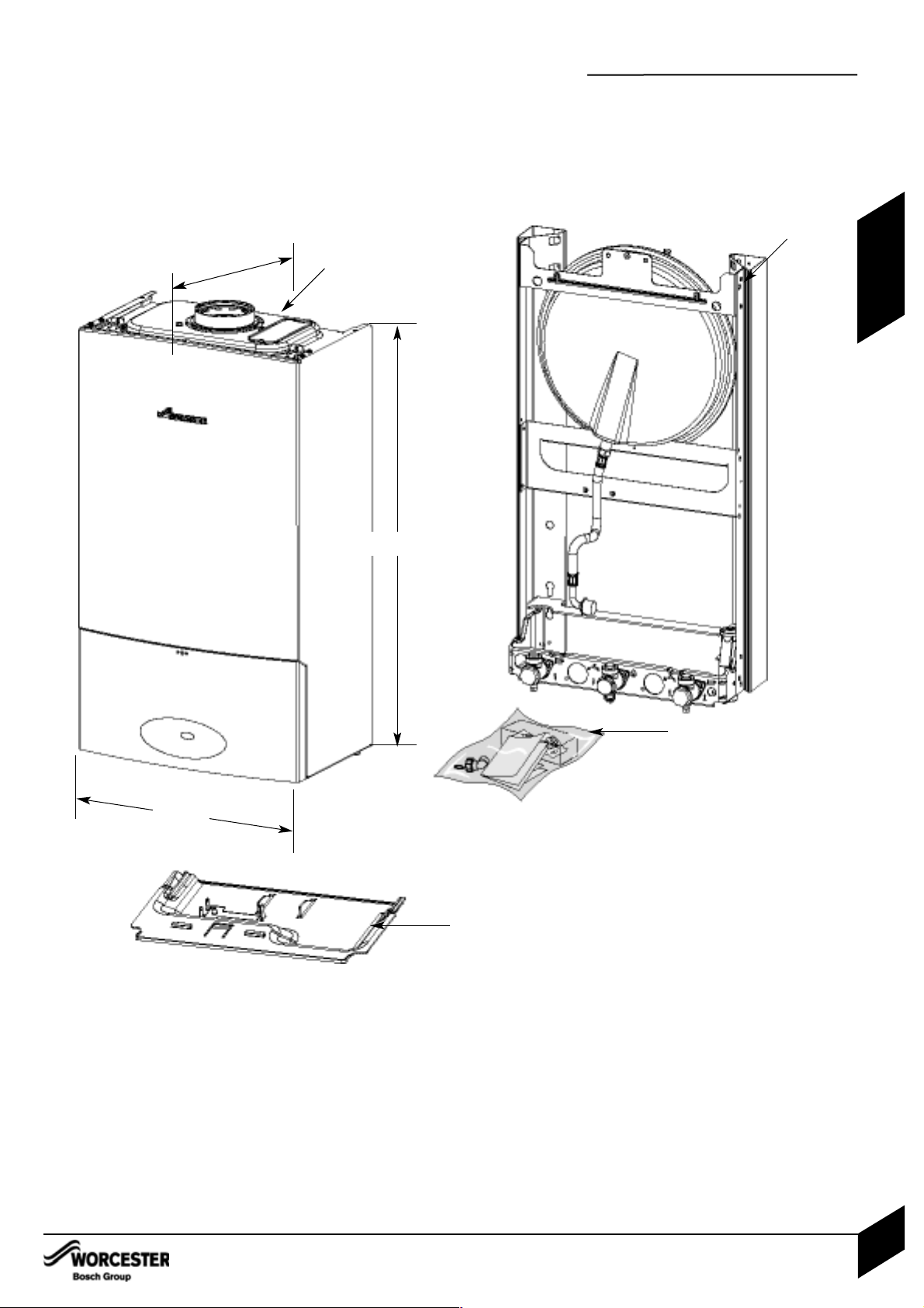
STANDARD PACKAGE:
A - Wall hung gas fired condensing boiler for
central heating and indirect domestic hot water
B - Boiler support frame/pre-plumbing jig
C -Hardware literature pack
D - Bottom Panel
SPECIFICATIONS:
Pre-wired and pre-plumbed
Galvanised steel inner frame
Digital control system
Automatic ignition
Direct burner ignition electrodes
Built-in frost thermostat
Built-in fault finding diagnostics
Modulating automatic gas valve
Combustion air fan with speed regulator
CH temperature sensor & control
Pump anti-seizure protection
Flue gas temperature limiter
Condensate trap & syphon
700mm
400mm
A
D
330mm
GENERAL INFORMATION
INSTALLATION & SERVICING INSTRUCTIONS FOR WORCESTER BOSCH GREENSTAR 12i System/24i System
8 716 107 375a (02/05)
4
APPLIANCE
INFORMATION
B
C
D
(When fitted to wall frame)
Depth to wall

TECHNICAL DATA
INSTALLATION & SERVICING INSTRUCTIONS FOR WORCESTER BOSCH GREENSTAR 12i System/24i System
8 716 107 375a (02/05)
5
TECHNICAL DATA
APPLIANCE
INFORMATION
Gas flow rate - Max. 10 minutes from lighting
Natural Gas G20 m3/h 1.33 2.67 - -
Propane Gas (LPG) kg/h - - 0.46 1.91
Central Heating
Max. rated heat input KW 12.32 24.62 12.32 24.62
Min. heat input KW 3.70 7.38 5.95 9.64
Max. rated heat output 40/30°C KW 12.85 25.67 25.67 25.67
Max. rated heat output 50/30°C KW 12.74 25.45 12.74 25.45
Max. rated heat output 80/60°C KW 12 24 12 24
Max. flow temperature °C 82 82 82 82
Min. output °C 4.0 7.90 6.37 10.3
Max. flow temperature to cylinder (when used with integral optional diverter valve) °C 75 75 75 75
Max. permissible operating pressure bar 2.5 2.5 2.5 2.5
Available pump head at 21°C system temperature rise m 2.0 2.0 2.0 2.0
Flue
Flue Gas Temp. 80/60°C, rated/min. load °C 62/56 78/63 62/57 79/64
Flue Gas Temp. 40/30°C, rated min. load °C 41/33 54/35 43/35 55/38
CO2level at max. rated heat output % 9.8 9.8 11.0 11.0
CO2level at min. rated heat output % 9.2 9.2 10.5 10.5
NOx - class 5555
Condensate
Max. condensation rate l/h 0.93 2.0 0.93 2.0
pH value, approx. 4.8 4.8 4.8 4.8
Electrical
Electrical power supply voltage AC...V 230 230 230 230
Frequency Hz 50 50 50 50
Max. power consumption W 140 140 140 140
General Data
SEDBUK band AAAA
Appliance protection rating IP X4D X4D X4D X4D
Permissable ambient temperatures °C 0-50 0-50 0-50 0-50
Nominal capacity of appliance Itr 3.9 3.9 3.9 3.9
Noise output level (Max central heating) dB(A) 42 42 42 42
Packaged boiler weight kg 44.4 44.4 44.4 44.4
Total boiler weight kg 39.5 39.5 39.5 39.5
Lift weight kg 27.1 27.1 27.1 27.1
SEDBUK % 90.1 90.2 91.4 92.0
DESCRIPTION NATURAL GAS L.P.G.
UNITS 12i System 24i System 12i System 24i System
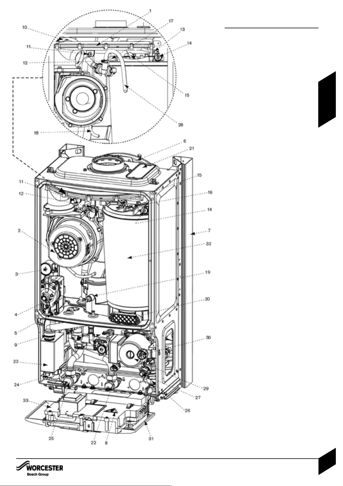
LAYOUT & COMPONENTS
The diagram opposite shows the controls in the
servicing position and excludes the outer case.
1 AIR / GAS MANIFOLD
2FAN
3 AIR / GAS ADJUSTMENT SCREW
4GAS VALVE
5 INLET PRESSURE TEST POINT
6 EXPANSION VESSEL
7 WALL MOUNTING FRAME
8 COVER FOR EXTERNAL WIRING
CONNECTIONS
9 CONDENSATE CONNECTION FROM
HEAT EXCHANGER
10 FLUE PRESSURE SWITCH
11 FAN PRESSURE TEST POINT
12 MANUAL VENT POINT
13 IGNITION AND FLAME SENSE ELECTRODES
14 OVERHEAT THERMOSTAT
15 FLAME VIEWING MIRROR
16 SECURING NUT, AIR /
GAS MANIFOLD CLAMP
17 SENSOR - BOILER FLOW
18 FLUE AIR PRESSURE SWITCH
CONNECTION
19 FLUE OVERHEAT THERMOSTAT
20 ACCESS POINT FOR CLEANING HEAT
EXCHANGER/SUMP
21 REMOVABLE TOP CASE PANEL FOR
SERVICING
22 GAS INLET CONNECTION 22mm
COMPRESSION
23 TRAP / SYPHON
24 TRAP / SYPHON OUTLET
CONNECTION ( 22mm PLASTIC PIPE)
25 FLOW
26 RETURN
27 DRAIN POINT
28 SILICONE TUBE (USE TO VENT AIR
FROM HEAT EXCHANGER)
29 PUMP
30 SYSTEM PRESSURE GAUGE
31 CONTROL PANEL IN SERVICE
POSITION
32 HEAT EXCHANGER
33 ACCESS COVER FOR TRANSFORMER &
PCB
LAYOUT & COMPONENTS
INSTALLATION & SERVICING INSTRUCTIONS FOR WORCESTER BOSCH GREENSTAR 12i System/24i System
8 716 107 375a (02/05)
6
APPLIANCE
INFORMATION
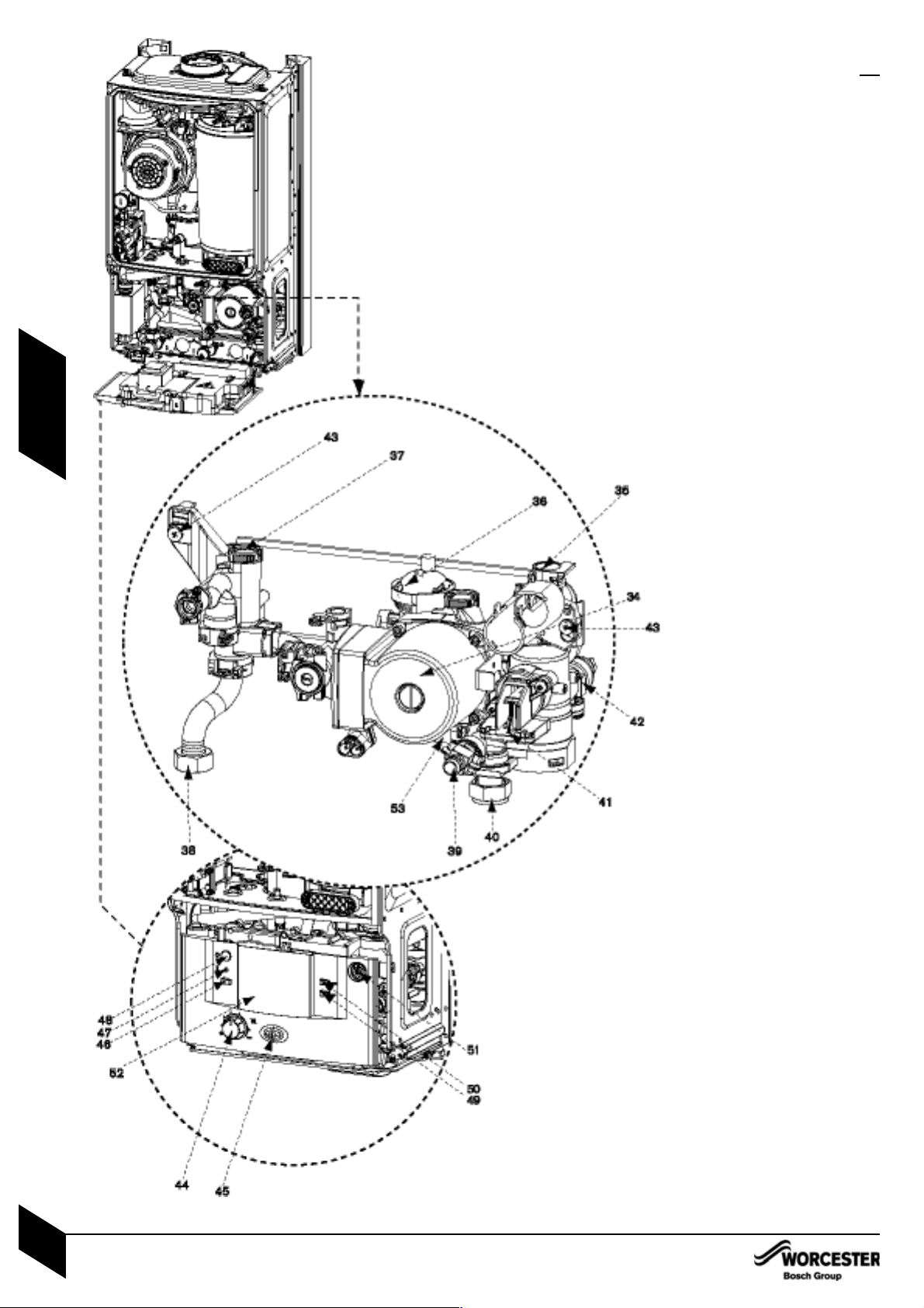
LAYOUT & COMPONENTS
34 SYSTEM PUMP
35 UNUSED PORT
36 AUTO AIR VENT
37 FLOW CONNECTION FROM BOILER
HEAT EXCHANGER
38 FLOW CONNECTION TO
SERVICE VALVE
39 DRAIN POINT
40 RETURN CONNECTION TO
SERVICE VALVE
41 OPTIONAL INTEGRAL DIVERTER VALVE
POSITION
42 PRESS URE REL IEF VALVE
43 COMPACT HYDRAULIC MOUNTING
SCREW (2) TO BOILER
44 CH TEMPERATURE CONTROL
45 MAINS ON/OFF INDICATOR/
DIAGNOSTIC LIGHT (BLUE)
46 SERVICE MODE BUTTON
47 BURNER ON INDICATOR LIGHT (GREEN)
48 MASTER SWITCH ON/OFF
49 NOTUSED
50 FAULT RESET BUTTON
51 SYSTEM PRESSURE GAUGE
52 POSITION FOR OPTIONAL
PROGRAMMER
53 INTERNAL BYPASS WITHIN
PLASTIC MOULDING
LAYOUT & COMPONENTS
INSTALLATION & SERVICING INSTRUCTIONS FOR WORCESTER BOSCH GREENSTAR 12i System/24i System
8 716 107 375a (02/05)
7
APPLIANCE
INFORMATION

CLEANING PRIMARY SYSTEMS
BEFORE CLEANING THE SYSTEM:
ENSURE TH E SYSTEM AND PIPEWORK IS
IN GOOD WORKING ORDER
KEEP THE EXISTING BOILER/
CIRCULATING PUMP WHERE POSSIBLE
OR USE A POWER FLUSHING MACHINE
TO AID THE CLEANSING PROCEDURE
BEFORE INSTALLING A NEW BOILER.
CLEANING THE PRIMARY SYSTEM:
1 Fill the system with cold water and
check for leaks.
2 Open all drain cocks and drain the
system.
3 Close drain cocks and add a suitable
flushing agent at the correct strength for
the system condition in accordance with
the manufacturer's instructions.
Circulate the flushing agent before the
boiler is fired up.
4 Run the boiler/system at normal operating
temperature as directed by the manufacturer
of the flushing agent.
5 Drain and thoroughly flush the system to
remove the flushing agent and debris.
IMPORTANT: All the following Pre-Installation sections must be read and
requirements met before starting boiler or flue installation.
CAUTION: ISOLATE THE MAINS SUPPLIES BEFORE STARTING ANY WORK AND
OBSERVE ALL RELEVANT SAFETY PRECAUTIONS.
IMPORTANT: Debris from the system can
damage the boiler and reduce efficiency.
Failure to comply with the guidelines for
the use of water treatment with the
appliance will invalidate the appliance
warranty.
1
2
3
4
5
KEY
Valve
Flushing
Agent
CLEANING PRIMARY SYSTEMS
INSTALLATION & SERVICING INSTRUCTIONS FOR WORCESTER BOSCH GREENSTAR 12i System/24i System
8 716 107 375a (02/05)
8
PRE -
INSTALLATION
MAINS SUPPLY
ELECTRIC SUPPLY:
• Supply: 230V - 50Hz, 50 watts not including
pump.
• Cable: PVC insulated 0.75mm2(24 x 0.2mm)
temperature rated to 90°C.
• External 3A fuse to BS1362.
• The appliance must be earthed.
• IPX4D.
• All pipes to the boiler must be cross-bonded.
• Mains supply to the boiler and system wiring
centre must be through one common fused
double pole isolator situated adjacent to the
appliance.
• Wiring must comply with IEE wiring regulations
and any local regulations which may apply to
fixed wiring to a stationary appliance.
• Any system connected to the boiler must not
have a separate electrical supply.
GAS SUPPLY:
• Boilers using NG must be connected to a
governed meter.
• LPG boilers must be connected to a
regulator.
• Installation and connection of the gas supply
to the boiler must be in accordance with
BS6891.
• Under no circumstances should the size of
the gas supply pipe be less than that of the
appliance inlet connection.
• The meter or regulator and pipework to the
meter must be checked, preferably by the gas
supplier, to ensure it is in good working order
and can meet the gas flow and pressure
requirements in addition to the demand from
any other appliance being served.
MAINS SUPPLY
INSTALLATION & SERVICING INSTRUCTIONS FOR WORCESTER BOSCH GREENSTAR 12i System/24i System
8 716 107 375a (02/05)
9
PRE -
INSTALLATION
WATER SYSTEMS & PIPEWORK
INSTALLATION & SERVICING INSTRUCTIONS FOR WORCESTER BOSCH GREENSTAR 12i System/24i System
8 716 107 375a (02/05)
10
PRE -
INSTALLATION
WATER SYSTEMS & PIPEWORK
PLASTIC PIPEWORK & UNDER FLOOR
HEATING:
• Any plastic pipework must have a polymeric
barrier with 600mm (minimum) length of
copper or steel pipe connected to the boiler.
• Plastic pipework used for underfloor heating
must be correctly controlled with a
thermostatic blending valve limiting the
temperature of the circuits to approx. 50°C.
CONNECTIONS/VALVES:
• All system connections, taps and mixing
valves must be capable of sustaining a
pressure up to 3 bar.
• Radiator valves should conform to
BS2767:10.
• All other valves should conform to BS1010.
• On new installations TRV’s must be used on
all radiators except where a room thermostat
is sited. On all installations they should at
least be fitted in the sleeping areas. See note
below on open radiator/bypass
• A drain cock is required at the lowest point
on the system.
• An air vent is required at the highest point on
the system.
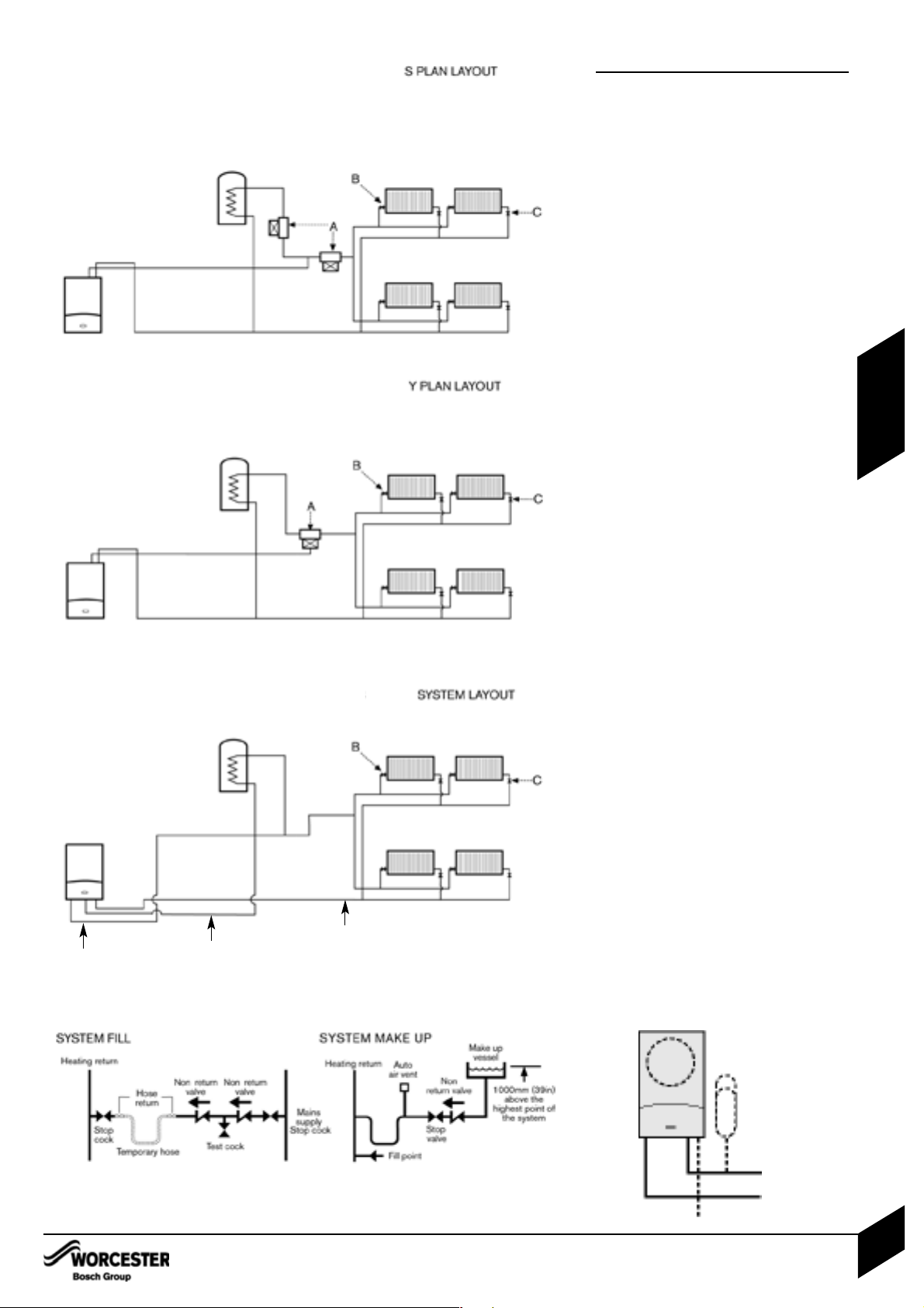
S and Y PLAN SYSTEM:
• NB The boiler is fitted with its own internal
bypass.
A Diverter Valve
B Radiator Valve (Flow)
C Lockshield Valve (Return)
• NB A drain cock should be fitted at the
lowest point of the heating circuit and
beneath the appliance.
OPTIONAL INTERNAL DIVERTER VALVE:
This boiler is designed to operate on a sealed
system only. The boiler will require a second
return pipe from the water cylinder to the wall
mounting frame and terminate in 15mm copper
pipe.
• The CH sealed system must be filled using a
WRAS approved filling loop or comply with
the diagram opposite for system fill.
• Where the system volume is more than 100
litres or exceeds 2.65 bar at maximum
heating temperature, an extra expansion
vessel (B) must be fitted as close as possible
to the appliance in the central heating return.
• Pressurise the extra expansion vessel (B) to
the same figure as the expansion vessel built
into the appliance.
• Do not use galvanised pipes or radiators.
WITH EXTERNAL DIVERTER VALVE
Boiler flow
Return from
cylinder
Return from
central heating
WITH OPTIONAL INTERNAL DIVERTER VALVE FITTED
(NOT SUPPLIED WITH BOILER)
A
B
CONDENSATE PIPEWORK
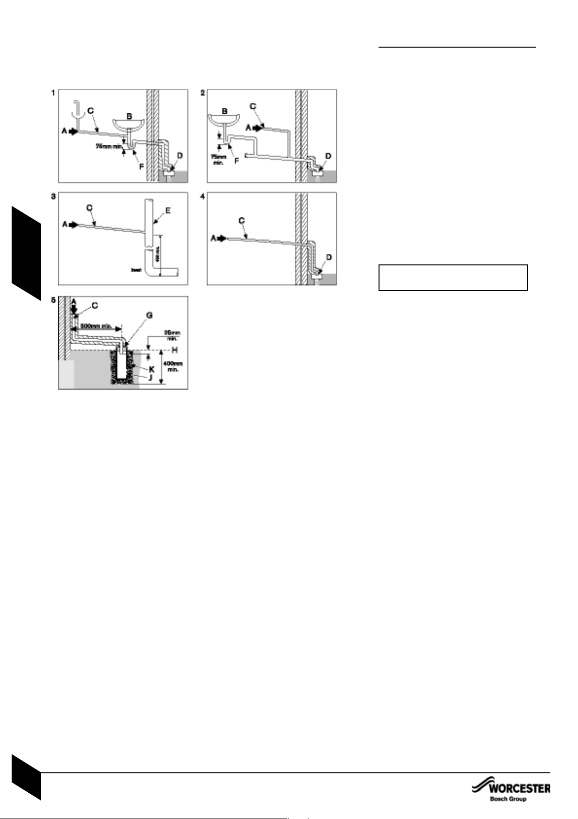
CONDENSATE PIPEWORK:
• The condensate pipe must be a minimum of
22mmØ plastic pipe.
• The condensate pipework must fall at
least 50mm per metre towards the outlet
and should take the shortest practicable
route.
• The pipework must follow one of the options
shown opposite into an internal serviceable
trap (min. 75mm) such as a sink/washing
machine waste or discharge direct into a vent
stack (E) 450mm min. above pipe invert, or
into a gulley (D) below ground but above the
water level.
• Use waterproof pipe insulation in exposed
positions and for external pipework.
1 Internal sink/washing machine drain
2 Internal waste drainage system
3 Soil/vent stack
4 External drainage system
5 External condensate absorption point
A - Condensate from boiler
B - Sink
C - 22mmØ plastic condensate pipe
D - Gulley
E - Internal soil and vent stack
F - Serviceable waste trap (75mm min)
G - 300mm x 100mmØ sealed plastic tube
H - Ground level
J - Drainage holes 50mm from base of tube
(12mmØ at 25mm centres) facing away from
building
K - Limestone chippings
IMPORTANT: Ensure there are no
blockages in the pipe run.
CONDENSATE PIPEWORK
INSTALLATION & SERVICING INSTRUCTIONS FOR WORCESTER BOSCH GREENSTAR 12i System/24i System
8 716 107 375a (02/05)
11
PRE -
INSTALLATION
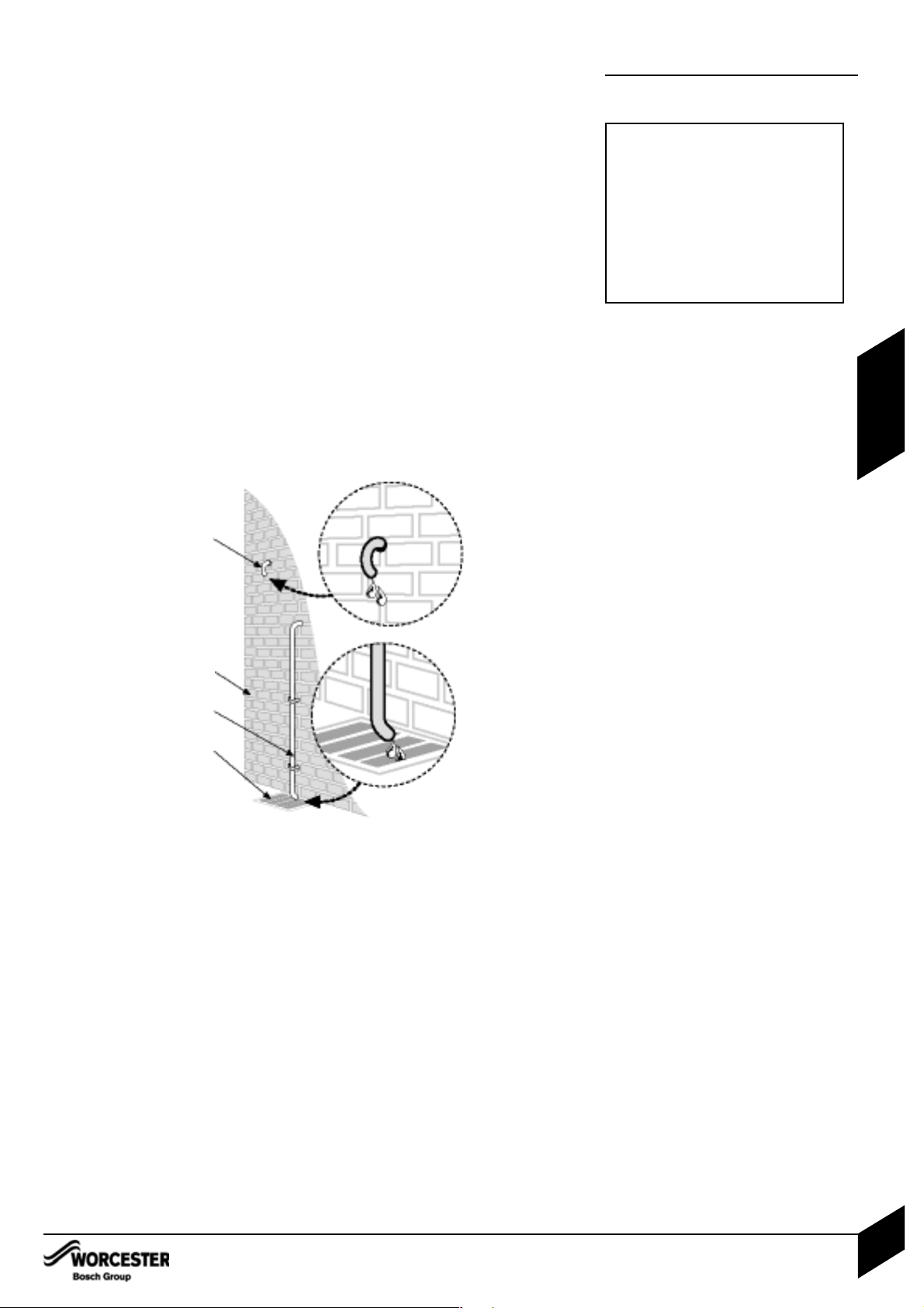
PRESSURE RELIEF PIPEWORK
PRESSURE RELIEF PIPEWORK:
• The pressure relief drain pipe (M) from the
boiler should be at least 15mm diameter
copper pipe and run downwards away from
any electrics or other hazard, preferably to an
external drain or soakaway.
• Pipe (M) should be finished with a partial
bend, near the outlet to face the external wall
(as shown) to help prevent hazard.
L - Outside wall
O,M - Drain pipe
N - External drain
IMPORTANT: The pressure relief valve
is a safety device for the boiler and if
activated may discharge boiling water
steam through the relief valve drain
pipe.
Care should be taken when siting the
outlet pipe so that it does not cause an
obstruction or discharge above a
window, entrance or other public access
where it could cause a hazard.
PRESSURE RELIEF PIPEWORK
INSTALLATION & SERVICING INSTRUCTIONS FOR WORCESTER BOSCH GREENSTAR 12i System/24i System
8 716 107 375a (02/05)
12
PRE -
INSTALLATION
M
N
O
L
BOILER LOCATION &
CLEARANCES
This boiler is only suitable for installing internally
within a property at a suitable location onto a
fixed, rigid non-combustible surface at least the
same size as the boiler and capable of supporting the boiler weight.
COMPARTMENTS:
Follow the requirements of BS6798 and
BS5440 Part 2 and note:
• Minimum clearances must be maintained
• An access door is required to install, service
and maintain the boiler and any ancilliary
equipment.
• If fitting the boiler into an airing cupboard
use a non-combustible perforated material
(maximum hole sizes of 13mm) to separate
the boiler from the airing space.
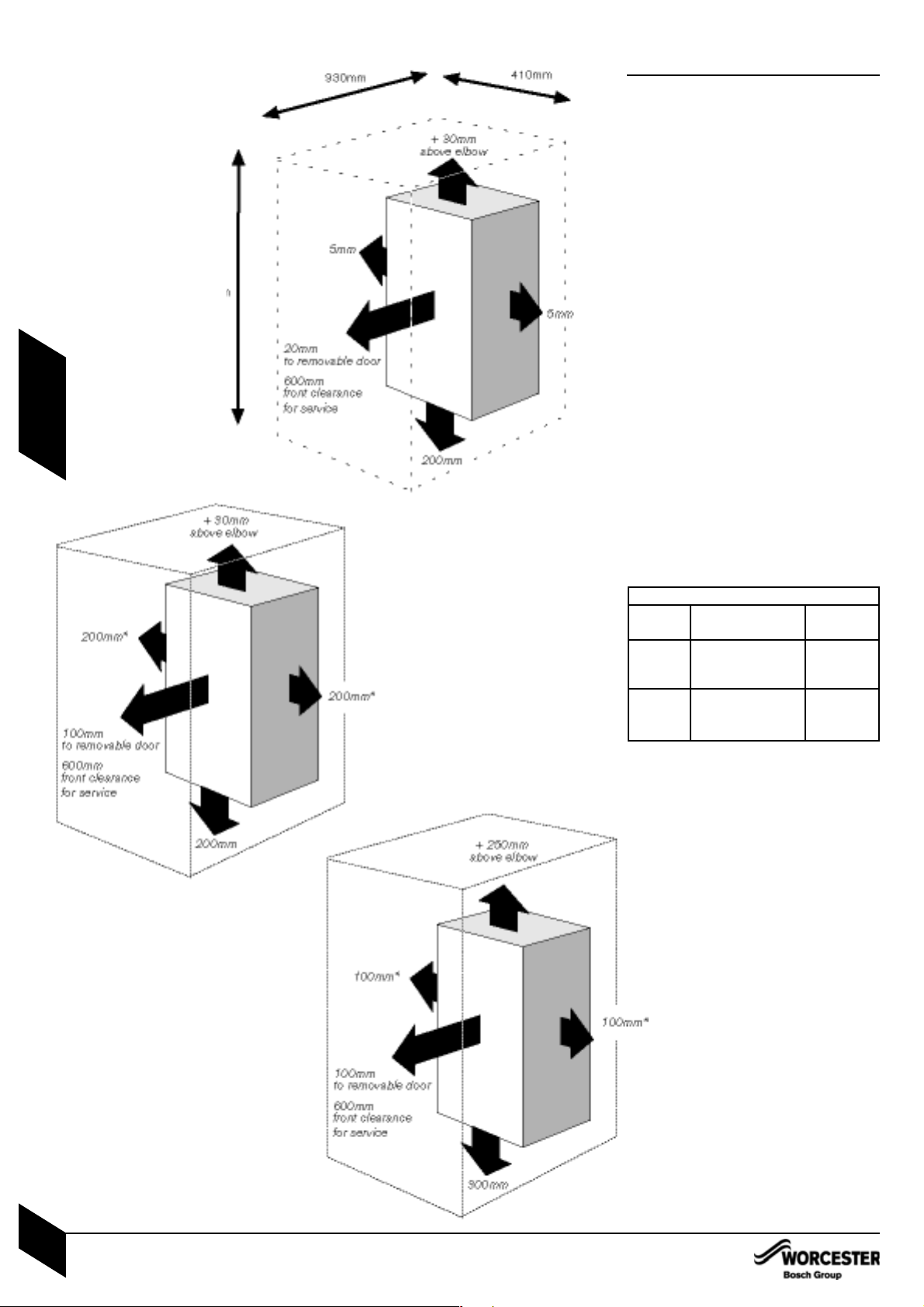
BOILER CLEARANCES:
The diagram opposite shows the minimum
space required to install and service the boiler.
If a boiler is installed in a compartment with
clearances less than shown in the diagrams A
and B, ventilation is required. Refer to tables
below for ventilation requirements.
BOILER CLEARANCES - UNVENTILATED
COMPARTMENTS:
The diagrams (A and B) opposite show two
options for the minimum space required to
install and service the boiler inside an unventilated compartment.
*This space can be reduced to 50mm for one
side only as long as both the side clearances
add up to the total of both the side
measurements shown or more.
12 & 24 kW
Vent To room or Direct to
position internal space outside
High Minimum free Minimum
level area 122 cm
2
free area
61 cm
2
Low Minimum free Minimum
level area 122 cm
2
free area
61cm
2
SERVICING CLEARANCES
VENTED COMPARTMENT
VENTILATION FREE
COMPARTMENTS
INSTALLATION CLEARANCES
Using 100mm flue kit
1080mm
Using 125mm flue kit
- 1110mm
BOILER LOCATION & CLEARANCES
INSTALLATION & SERVICING INSTRUCTIONS FOR WORCESTER BOSCH GREENSTAR 12i System/24i System
8 716 107 375a (02/05)
13
PRE -
INSTALLATION
A
B
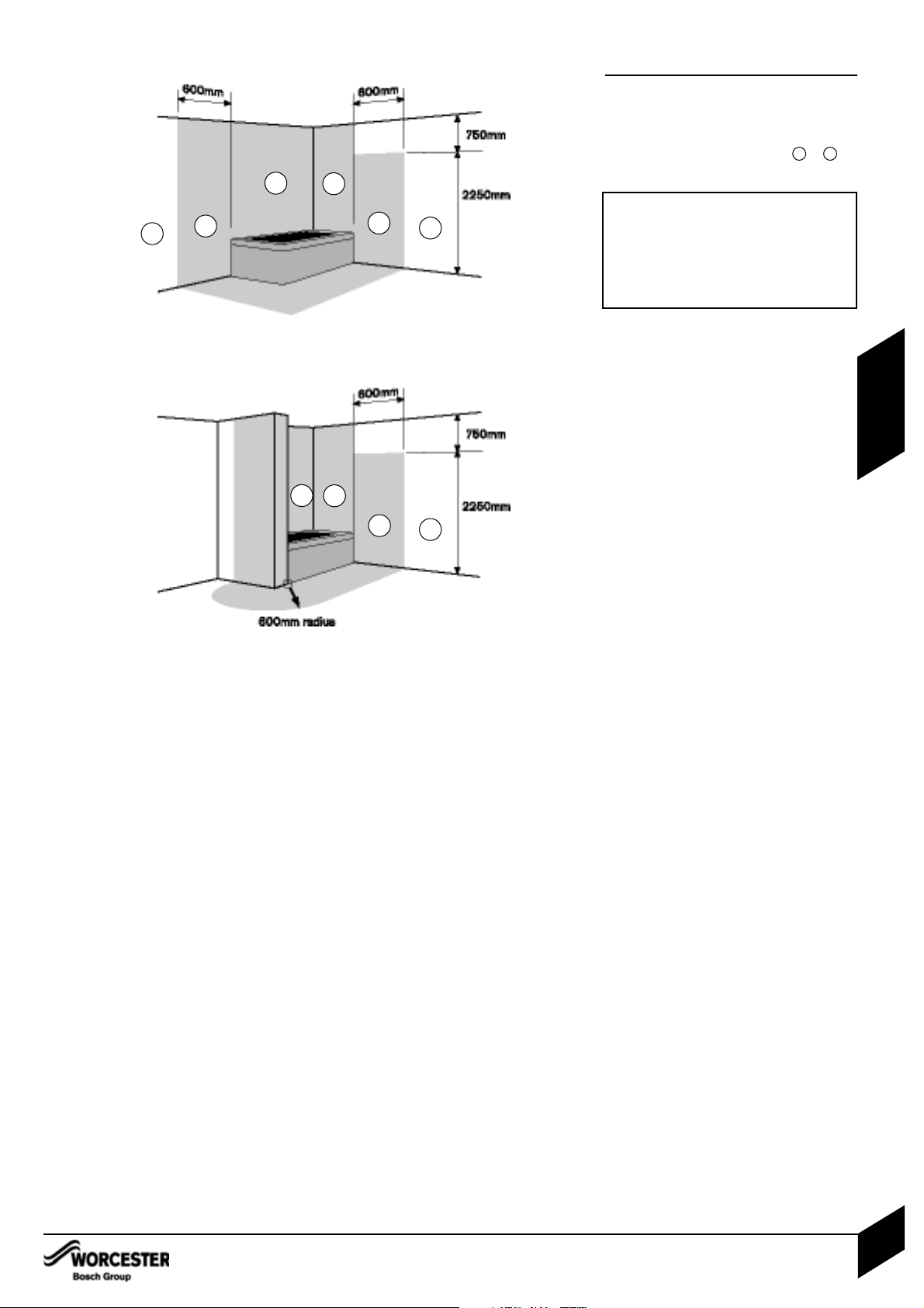
BATHROOMS:
The boiler can be installed in zones 2 or 3 .
See IEE wiring regulations.
BOILER LOCATION &
CLEARANCES
BOILER LOCATION & CLEARANCES
INSTALLATION & SERVICING INSTRUCTIONS FOR WORCESTER BOSCH GREENSTAR 12i System/24i System
8 716 107 375a (02/05)
14
PRE -
INSTALLATION
IMPORTANT: any switch or appliance
control using mains electricity must not be
able to be touched by a person using the
bath or shower.
Electrical switches, fused spur and socket
outlets must not be situated in the
bathroom.
1
1
2
3
2
3
1
1
2
3
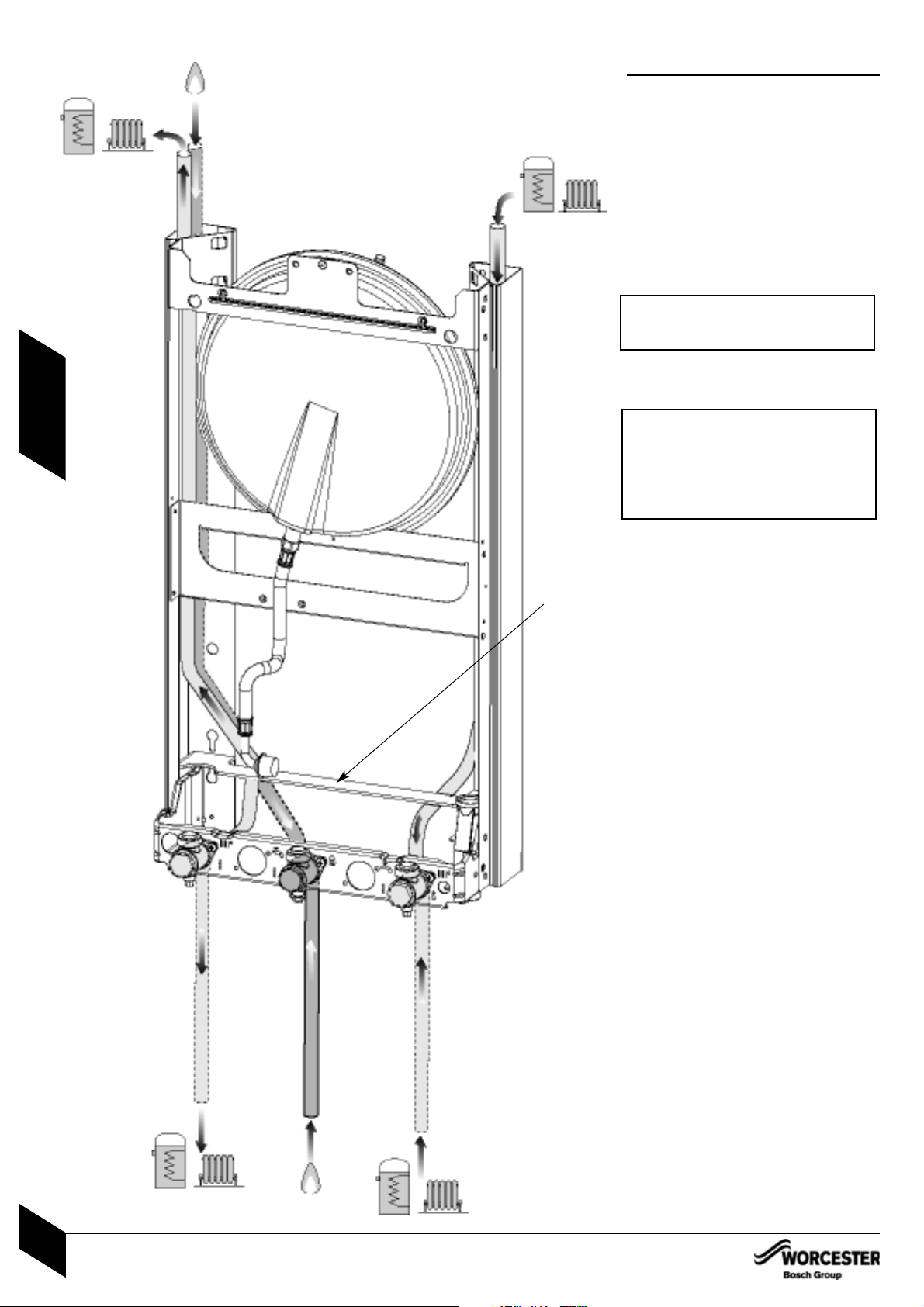
PLUMBING MANIFOLD
CONNECTIONS:
Heating System: 22mm compression fittings
Gas: 22mm compression fittings
Use the fittings supplied in the Lit/Hardware
pack.
• If the boiler pipes are to be run behind the
appliance ensure that the pipes pass through
the slot in the yellow plastic guide (A). This is
fitted to the boiler frame.
Return 22mm
Flow 22mm
PLUMBING MANIFOLD
INSTALLATION & SERVICING INSTRUCTIONS FOR WORCESTER BOSCH GREENSTAR 12i System/24i System
8 716 107 375a (02/05)
15
PRE -
INSTALLATION
Gas Supply (alternative from above appliance) 22mm
Mains Gas Supply 22mm
A
Further guidance on pipe routing can be
found printed on the boiler template
(supplied with the boiler).
IMPORTANT: IF FITTING OPTIONAL
INTEGRAL DIVERTER VALVE
Disregard this page and refer to the
correct version for installing the integral
diverter valve in the ADDITIONAL
INFORMATION section at the back of this
book.
Return 22mm
Flow 22mm
FLUE TERMINAL POSITIONS
• The flue must be fitted and terminated in
accordance with the recommendations of
BS5440 : Part 1.
• The flue must not cause an obstruction.
• Discharge and any noise from the flue outlet
must not cause a nuisance.
• Flue gases have a tendency to plume and in
certain weather conditions a white plume of
condensation will be discharged from the flue
outlet. This could be a nuisance, for example,
near security lighting.
• The air inlet/outlet duct and the terminal of
the boiler must not be closer than 25mm to
any combustible material.
Detailed recommendations on protection of
combustible materials are given in
BS 5440:1.
• A protective terminal guard must be fitted if
the terminal is 2m or less above a surface
to which people have access.
The guard must be spaced equally (minimum
50mm) around the flue and fixed to the wall
with plated screws.
See Contact Information (inside front cover).
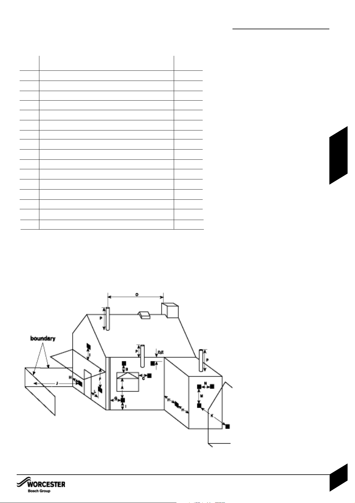
FLUE TERMINAL POSITIONS
INSTALLATION & SERVICING INSTRUCTIONS FOR WORCESTER BOSCH GREENSTAR 12i System/24i System
8 716 107 375a (02/05)
16
PRE -
INSTALLATION
Minimum dimensions of flue terminal positions for balanced room sealed flues with
fanned draught:
DRWG. TERMINAL POSITION DISTANCE
REF:
A
1
Directly below an opening, air brick, opening windows, etc. 300mm
B
1
Above an opening, air brick, opening window, etc. 300 mm
C
1
Horizontally to an opening, air brick, opening window, etc. 300 mm
D Below gutters, soil pipes or drain pipes 75mm
E Below eaves 200mm
F
2
Below balconies or car port roof (lowest point) 200mm
G From a vertical drain pipe or soil pipe 150mm
H From an internal or external corner 300mm
I Above ground, roof or balcony 300mm
J From a surface facing the terminal 600mm
K From a terminal facing the terminal 1200mm
L
2
From an opening in the car port (e.g. door, window) into the dwelling 1200mm
M Vertically from a terminal on the same wall 1500mm
N Horizontally from a terminal on the same wall 300mm
O From a non combustible vertical structure on the roof
P Above intersection with the roof
1 In addition, the terminal should not be nearer than 150mm (fanned draught) to an opening
in the building fabric formed for the purpose of accommodating a built-in element such as a
window frame.
2 Not recommended.
See instructions supplied with vertical flue kits.
*
*
*
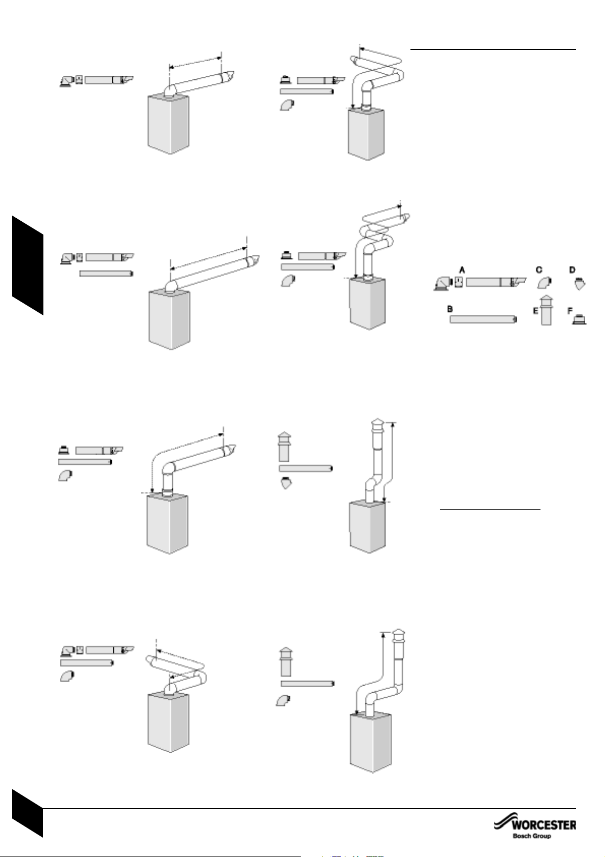
FLUE OPTIONS
• The diagrams (opposite) show the
components used and the maximum flue
length for each configuration of 100mm and
125mm flues.
• Shaded flue components indicate the
standard 100mm horizontal flue.
• Only straight flue sections can be reduced in
length and cut.
• The flue terminal end can be fitted from the
inside or outside of the building.
• Fixing kits are supplied with the flue extension
kits.
• Horizontal 125mm and Vertical 100mm and
125mm flue kits are available with separate
instructions. Contact your supplier or
Worcester Bosch.
A - Standard horizontal flue (100mm diameter
shown)
B - Straight flue extension
C - Flue bend 90°
D - Flue bend, 45°
E - Vertical terminal (vertical adaptor supplied
with terminal)
F - Vertical adaptor (used with horizontal
terminal)
Calculating the flue length:
Measure the total flue length required, noting
that the maximum straight flue length including
the terminal is:
Horizontal 60/100mm: 4600mm
Horizontal 80/125mm: 13000mm
Vertical 60/100mm: 6400mm
Vertical 80/125mm: 15000mm
Then reduce the total straight flue length for
each extra flue bend (excluding the flue elbow)
by:
2000mm for 90°
1000mm for 45°
Flue Extension lengths:
Horizontal & Vertical 60/100mm: 960mm
Horizontal & Vertical 80/125mm: 1000mm
Flue Terminal lengths:
Horizontal 60/100mm: 800mm including terminal
Horizontal 80/125mm: 1200mm
Vertical 60/100mm: 1140mm to top of terminal
Vertical 80/125mm: 1365mm to top of terminal
STANDARD FLUE HORIZONTAL
Ø100
MAX 686 A x 1
MIN 250 A x 1*
Ø125
MAX 1070 A x 1
MIN 250 A x 1*
* Requires cutting
MAXIMUM FLUE HORIZONTAL
Ø100 - 4600mm
A x 1 + B x 5
Ø125 - 13000mm
A x 1 + B x 13
MAXIMUM FLUE VERTICAL START + 1 BEND
Ø100 - 4600mm
A x 1 + C x 1 + B x 5 +
Fx1
Ø125 - 13000mm
A x 1 + C x 1 + B x 13 +
Fx1
Ø100 - 2600mm
A x 1 + B x 3 + C x 1
Ø125 - 11000mm
A x 1 + B x 11 + C x 1
MAXIMUM FLUE HORIZONTAL + 1 BEND
MAXIMUM FLUE VERTICAL
START + 2 BENDS
Ø100 - 2600mm
A x 1 + C x 2 + B x 4 +
Fx1
Ø125 - 11000mm
A x 1 + C x 2 + B x 13 +
Fx1
Ø100 - N/A
Ø125 - 9000mm
A x 1 + C x 3 + B x 11 +
Fx1
MAXIMUM FLUE VERTICAL
WITH 2 x 45° BENDS
Ø100 - 4400mm
(including terminal)
B x 5 + D x 2 + E x 1
Ø125 - 13000mm
(including terminal)
B x 13 + D X 2 + E x 1
Ø100 - 2400mm
(including terminal)
B x 4 + C x 2 + E x 1
Ø125 - 11000mm
(including terminal)
B x 13 + C x 2 + E x 1
VERTICAL FLUE WITH
2 x 90° BENDS
A
A
B
A
B
F
C
A
B
C
F
B
C
A
F
B
C
A
E
B
D
E
B
C
MAXIMUM FLUE VERTICAL
START + 3 BENDS
FLUE OPTIONS
INSTALLATION & SERVICING INSTRUCTIONS FOR WORCESTER BOSCH GREENSTAR 12i System/24i System
8 716 107 375a (02/05)
17
PRE -
INSTALLATION

A - Straps
B - Outer carton
C - Installer pack
D - Bottom panel
E - Wall mounting frame
F - Wall template ( in wall frame protective wrapping)
G - Inner packaging
IMPORTANT HANDLING INSTRUCTIONS
• It is advised that two people are used to carry
the carton from the van to the point of delivery.
• Once the carton has been delivered, the outer
carton is removed first. Care should be taken
when releasing the straps. If a sharp implement
is used make sure the outer carton is not
pierced and that the implement is used in such
a way so that it may not cause personal injury.
All sharp objects must be covered or the blade
retracted after use and put away in a safe
place. The wall mounting frame, Installer
pack, template and bottom panel are now
removed. Care should be taken when lifting the
boiler from the base and the proper technique
for safe lifting of any heavy object should be
strictly observed.
Additional requirements for roof space
installation:
• The boiler should be first unpacked before
ascending ladder to loft space.
• Two sets of steps should be used.
• Two people should share the lifting of the
boiler up to the loft hatch, where the boiler is
entered into the loft space tilted and slid on its
back into the loft.
Once the appliance is removed from its
packaging check the contents against the
packing list.
Before installing appliance ensure system has
been cleaned as explained on page 8.
1. Remove straps (A) and open the top of the
boiler packaging.
2. Remove template (F) and wall mounting
frame (E) from the packaging.
3. Remove boiler bottom panel (D) and
installer pack (C).
UNPACKING WALL FRAME AND
ANCILLARY ITEMS
LIFTING AND CARRYING PRECAUTIONS:
• Lift only a manageable weight, or ask for
help.
• When lifting or putting things down, bend
the knees, and keep the back straight
and feet apart.
• Do not lift and twist at the same time.
• Lift and carry objects close to the body
I
IM PORTANT: All the previous Pre-Installation sections must be read
and requirements met before starting boiler or flue installation.
E
F
A
B
C
D
G
UNPACKING WALL FRAME AND
INSTALLATION & SERVICING INSTRUCTIONS FOR WORCESTER BOSCH GREENSTAR 12i System/24i System
8 716 107 375a (02/05)
18
INSTALLATION
1
2
3
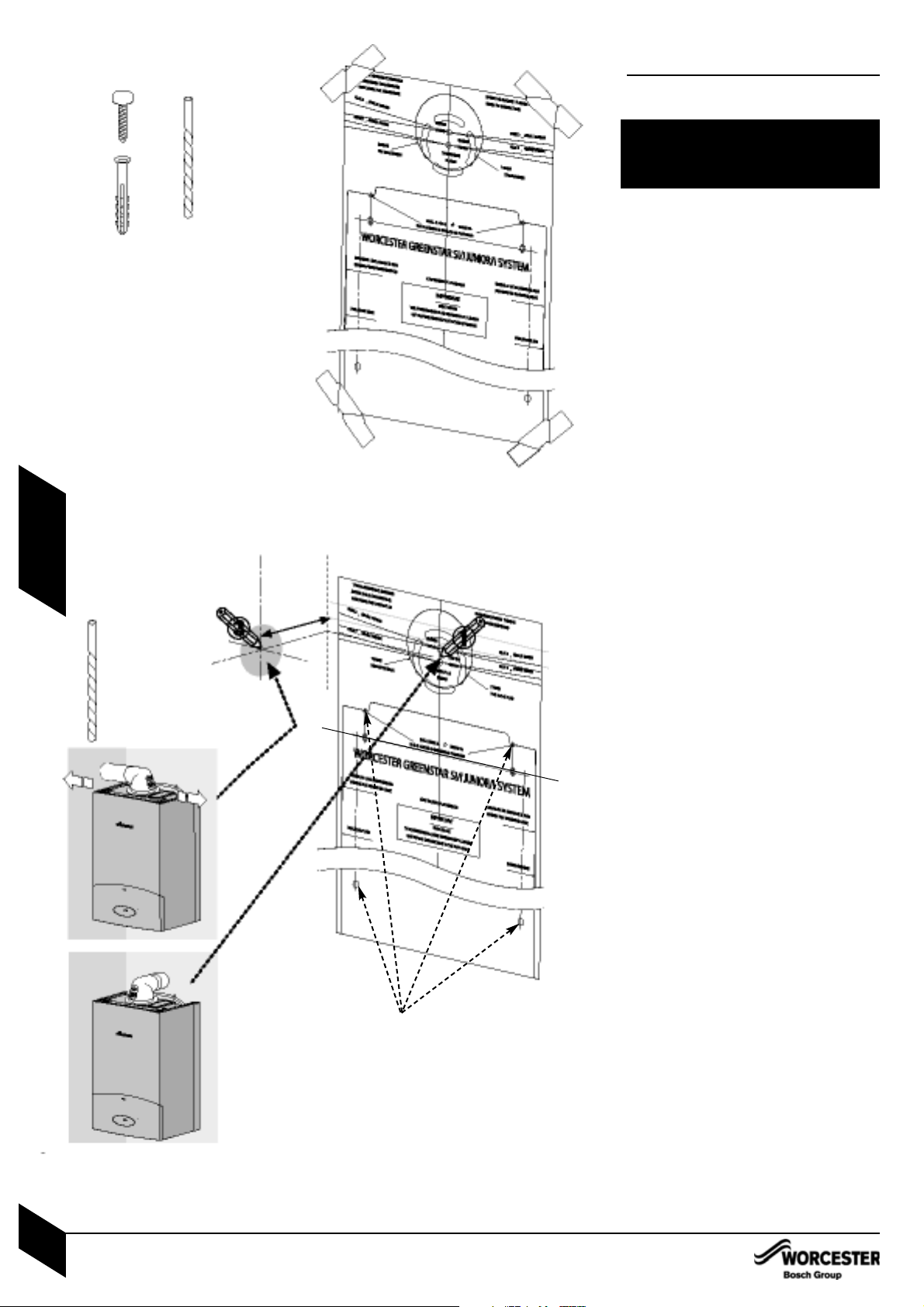
SAFETY:
All relevant safety precautions must be undertaken.
Protective clothing, footwear, gloves and safety
goggles must be worn as appropriate.
FIXING THE MOUNTI NG FRAME:
• The boiler template shows the relative
positions of the flue and the top and bottom
fixing of the mounting frame.
Fix the template to the wall in the desired
position (A).
Drill 4 holes for the wall mounting frame
through the template (2).
NOTE: The template has been sized to allow for
minimum clearances of 5mm sides, 200mm
base and 30mm above a Ø100mm flue elbow.
REAR FLUE OUTLET
• The drawing (B) opposite shows the boiler
template with the flue centre lines of both the
100mm and 125mm flue systems.
Mark centreline of flue to be used (1) the
external diameter of the hole can also be
marked if required.
• If a Ø100mm diameter flue is to be used,
a125mm diameter hole is required. However, if
using the weather sealing collar by pushing it
through from inside the property, then a
150mm diameter hole is required to
accommodate this.
• The terminal section of the 100mm flue has an
inbuilt 3° angle.
If extensions are to be added then the complete
flue must rise at an angle of 3°.
• The 125mm Ø flue system will require the flue
to rise at an angle of 3°.
Drill hole using a core drill or similar.
SIDE OUTLET:
Mark from the centre line of the wall template
to the wall which the flue will pass through (3).
Allow for a rise of 52mm per metre length of
flue, to give a 3° angle.
Clear any debris from the site.
CAUTION: Ensure there are no pipes,
electric cables, damp proof courses or
other hazards before drilling.
X 6
X 6
10mm Ø
WALL MOUNTING TEMPLATE
FLUE OPENING
127 m m
WALL MOUNTING PLATE FLUE OPENING
INSTALLATION & SERVICING INSTRUCTIONS FOR WORCESTER BOSCH GREENSTAR 12i System/24i System
8 716 107 375a (02/05)
19
INSTALLATIONCOMMISSIONING
2
A
B
4
7
6
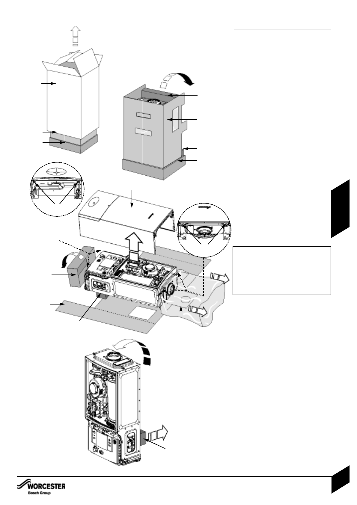
UNPACKING THE APPLIANCE
UNPACKING THE APPLIANCE
A - Outer carton
B - Inner sleeve (unwraps from front)
C - Packaging base
D - Protective wrapping
E - Appliance outer case
F - Protective inner packaging
4. Remove outer carton (A) and place
safely away from the working area.
5. With the outer packaging removed and
the inner sleeve (B) still in place gently
lay the boiler on its back.
6. The boiler will lie at an angle to the
floor to allow the boiler outer casing (E)
to be removed. The inner sleeve (B)
opens as shown. Remove the protective
wrapping (D) and undo the four screws,
two at the bottom of the boiler (H) and
two at the top (H) (see diagrams 6.1 and
6.2). Remove any packaging within the
boiler and the packaging base (C).
7. Stand boiler upright and remove the
protective inner packaging (F) at the rear
of the boiler.
UNPACKING THE APPLIANCE
INSTALLATION & SERVICING INSTRUCTIONS FOR WORCESTER BOSCH GREENSTAR 12i System/24i System
8 716 107 375a (02/05)
20
INSTALLATION
A
5
B
C
F
B
C
F
H
H
B
C
D
E
F
F
6.1
6.2
If fitting the optional integral diverter
valve, the copper pipe within the kit
should be fitted to the boiler before
hanging on the wall mounting frame.
See “OPTIONAL DIVERTER VALVE”
Section in these instructions or the
instructions supplied with the optional
diverter valve kit.
 Loading...