

Bosch Worcester GR8700iW 30 S NG, Worcester GR8700iW 35 S LPG, Worcester GR8700iW 35 SB NG, Worcester GR8700iW 30 S LPG, Worcester GR8700iW 30 SB LPG Installation And Maintenance Instructions Manual
...
Installation and Maintenance Instructions
Gas fired condensing system boiler
Greenstar 8000 Style
GR8700iW 30 S | GR8700iW 35 S | GR8700iW 30 SB | GR8700iW 35 SB
6720883855 (2019/01) UK/IE

Table of contents
Table of contents
1 Explanation of symbols and safety instructions . . . . . . . . . . . 3
1.1 Explanation of symbols . . . . . . . . . . . . . . . . . . . . . . . . . . 3
1.2 General safety instructions . . . . . . . . . . . . . . . . . . . . . . . 4
2 Regulations . . . . . . . . . . . . . . . . . . . . . . . . . . . . . . . . . . . . . . . . . . 6
3 Product Information . . . . . . . . . . . . . . . . . . . . . . . . . . . . . . . . . . 6
3.1 About the appliance . . . . . . . . . . . . . . . . . . . . . . . . . . . . . 6
3.2 Misuse. . . . . . . . . . . . . . . . . . . . . . . . . . . . . . . . . . . . . . . . 6
3.3 Scope of delivery . . . . . . . . . . . . . . . . . . . . . . . . . . . . . . . 7
3.4 Declaration of Conformity . . . . . . . . . . . . . . . . . . . . . . . . 7
3.5 Appliance type overview . . . . . . . . . . . . . . . . . . . . . . . . . 7
3.6 Product identification . . . . . . . . . . . . . . . . . . . . . . . . . . . 7
3.7 Pipe work positions and flue outlet. . . . . . . . . . . . . . . . . 8
3.8 Designation of components. . . . . . . . . . . . . . . . . . . . . . . 9
3.9 Product data for energy consumption. . . . . . . . . . . . . . 10
3.10 Standard accessories. . . . . . . . . . . . . . . . . . . . . . . . . . . 10
4 Pre-Installation. . . . . . . . . . . . . . . . . . . . . . . . . . . . . . . . . . . . . .11
4.1 System preparation . . . . . . . . . . . . . . . . . . . . . . . . . . . .11
4.1.1 Artificially softened water . . . . . . . . . . . . . . . . . . . . . . . 11
4.1.2 Water systems and pipe work . . . . . . . . . . . . . . . . . . . .11
4.1.3 System layouts examples. . . . . . . . . . . . . . . . . . . . . . . . 12
4.1.4 System fill . . . . . . . . . . . . . . . . . . . . . . . . . . . . . . . . . . . . 13
4.2 Mains supply. . . . . . . . . . . . . . . . . . . . . . . . . . . . . . . . . .14
4.2.1 Electrical supply . . . . . . . . . . . . . . . . . . . . . . . . . . . . . . . 14
4.2.2 Gas supply . . . . . . . . . . . . . . . . . . . . . . . . . . . . . . . . . . .14
4.3 Appliance location and clearances . . . . . . . . . . . . . . . . 14
4.3.1 Appliance location . . . . . . . . . . . . . . . . . . . . . . . . . . . . . 14
4.3.2 Rooms containing a bath or shower . . . . . . . . . . . . . . . 15
4.3.3 Appliance clearances. . . . . . . . . . . . . . . . . . . . . . . . . . .15
4.4 Flue systems considerations . . . . . . . . . . . . . . . . . . . . . 16
4.4.1 Flue length . . . . . . . . . . . . . . . . . . . . . . . . . . . . . . . . . . . 16
4.4.2 Flue options . . . . . . . . . . . . . . . . . . . . . . . . . . . . . . . . . . 17
4.4.3 Plume management system. . . . . . . . . . . . . . . . . . . . . . 19
4.4.4 Flue terminal positions . . . . . . . . . . . . . . . . . . . . . . . . . 19
4.4.5 Plume re-direct and plume management terminal
positions . . . . . . . . . . . . . . . . . . . . . . . . . . . . . . . . . . . . . 22
4.5 Condensate discharge . . . . . . . . . . . . . . . . . . . . . . . . . . 24
4.5.1 Appliance siphonic condensate trap. . . . . . . . . . . . . . . 24
4.5.2 Condensate pipe work. . . . . . . . . . . . . . . . . . . . . . . . . . 24
4.5.3 Internal connections . . . . . . . . . . . . . . . . . . . . . . . . . . . 25
4.5.4 External connections . . . . . . . . . . . . . . . . . . . . . . . . . . . 25
4.6 Pressure relief discharge. . . . . . . . . . . . . . . . . . . . . . . . 27
4.6.1 Pressure relief pipe work. . . . . . . . . . . . . . . . . . . . . . . . 27
4.6.2 Alternative PRV connections - Combined PRV/
condensate. . . . . . . . . . . . . . . . . . . . . . . . . . . . . . . . . . . 28
4.7 Cleaning primary systems . . . . . . . . . . . . . . . . . . . . . . . 28
4.7.1 Flushing the system . . . . . . . . . . . . . . . . . . . . . . . . . . . . 29
5 Installation . . . . . . . . . . . . . . . . . . . . . . . . . . . . . . . . . . . . . . . . . 29
5.1 Position the appliance . . . . . . . . . . . . . . . . . . . . . . . . . . 31
5.1.1 Mounting frame fixing . . . . . . . . . . . . . . . . . . . . . . . . . . 31
5.2 Appliance connections . . . . . . . . . . . . . . . . . . . . . . . . . 32
5.3 Hanging the appliance . . . . . . . . . . . . . . . . . . . . . . . . . . 33
5.4 Flue turret/adaptor installation . . . . . . . . . . . . . . . . . . . 35
5.5 Electrical connection . . . . . . . . . . . . . . . . . . . . . . . . . . . 36
5.5.1 Installer connections . . . . . . . . . . . . . . . . . . . . . . . . . . . 36
5.5.2 Cable preparations . . . . . . . . . . . . . . . . . . . . . . . . . . . . 38
5.5.3 External controls - domestic installations. . . . . . . . . . . 38
6 Commissioning. . . . . . . . . . . . . . . . . . . . . . . . . . . . . . . . . . . . . . 39
6.1 Pre-Commissioning checks . . . . . . . . . . . . . . . . . . . . . . 39
6.2 Water treatment. . . . . . . . . . . . . . . . . . . . . . . . . . . . . . . 39
6.2.1 Filling the appliance and adding Inhibitor. . . . . . . . . . . 39
6.2.2 Adjusting the operating pressure of the heating
system . . . . . . . . . . . . . . . . . . . . . . . . . . . . . . . . . . . . . . 40
6.3 Starting the appliance . . . . . . . . . . . . . . . . . . . . . . . . . . 40
6.3.1 Control panel overview . . . . . . . . . . . . . . . . . . . . . . . . . 40
6.3.2 Turn on the appliance . . . . . . . . . . . . . . . . . . . . . . . . . . 40
6.3.3 Siphon filling mode . . . . . . . . . . . . . . . . . . . . . . . . . . . . 40
6.4 Chimney sweep mode . . . . . . . . . . . . . . . . . . . . . . . . . . 41
6.5 Parameters when optional integral diverter valve
kit is fitted. . . . . . . . . . . . . . . . . . . . . . . . . . . . . . . . . . . . 41
6.6 Checking gas inlet pressure. . . . . . . . . . . . . . . . . . . . . . 42
6.6.1 Checking the gas supply pressure. . . . . . . . . . . . . . . . . 42
6.7 Checking the gas rate. . . . . . . . . . . . . . . . . . . . . . . . . . . 43
6.8 Checking for gas leaks during operation. . . . . . . . . . . . 43
6.9 CO and combustion check. . . . . . . . . . . . . . . . . . . . . . . 43
6.10 Checking flue integrity. . . . . . . . . . . . . . . . . . . . . . . . . . 44
6.11 Flue gas analysis. . . . . . . . . . . . . . . . . . . . . . . . . . . . . . . 45
6.12 Finishing commissioning . . . . . . . . . . . . . . . . . . . . . . . . 45
6.12.1 Fitting the combustion casing . . . . . . . . . . . . . . . . . . . . 45
6.12.2 Fitting the appliance casing. . . . . . . . . . . . . . . . . . . . . . 46
6.12.3 Appliance/product guarantee . . . . . . . . . . . . . . . . . . . . 47
7 Settings in the service menu . . . . . . . . . . . . . . . . . . . . . . . . . . 47
7.1 Operating the service menu . . . . . . . . . . . . . . . . . . . . . 47
7.2 Service menu . . . . . . . . . . . . . . . . . . . . . . . . . . . . . . . . . 48
7.2.1 Overview of the service menu . . . . . . . . . . . . . . . . . . . . 48
7.2.2 Benchmark and Info menu. . . . . . . . . . . . . . . . . . . . . . . 50
7.2.3 Settings menu . . . . . . . . . . . . . . . . . . . . . . . . . . . . . . . . 51
7.2.4 Function check menu. . . . . . . . . . . . . . . . . . . . . . . . . . . 54
7.2.5 Reset menu. . . . . . . . . . . . . . . . . . . . . . . . . . . . . . . . . . . 54
7.3 Thermal disinfection . . . . . . . . . . . . . . . . . . . . . . . . . . . 54
8 Inspection and maintenance . . . . . . . . . . . . . . . . . . . . . . . . . . 55
8.1 Inspection and maintenance considerations . . . . . . . . 55
8.2 Resources for inspection and maintenance . . . . . . . . . 55
8.3 Inspection and maintenance steps . . . . . . . . . . . . . . . . 55
8.4 Component access . . . . . . . . . . . . . . . . . . . . . . . . . . . . 56
8.5 Fan pressure test . . . . . . . . . . . . . . . . . . . . . . . . . . . . . . 56
8.6 Check working gas inlet pressure . . . . . . . . . . . . . . . . . 57
8.7 Flue gas analysis. . . . . . . . . . . . . . . . . . . . . . . . . . . . . . . 57
8.8 Checking the flue integrity. . . . . . . . . . . . . . . . . . . . . . . 57
8.9 Cleaning the siphon and heat exchanger . . . . . . . . . . . 57
8.9.1 Checking the burner . . . . . . . . . . . . . . . . . . . . . . . . . . . 58
8.9.2 Checking the non-return valve in the air-gas
manifold . . . . . . . . . . . . . . . . . . . . . . . . . . . . . . . . . . . . . 58
8.9.3 Fan removal . . . . . . . . . . . . . . . . . . . . . . . . . . . . . . . . . . 59
8.9.4 Cleaning the heat exchanger . . . . . . . . . . . . . . . . . . . . . 59
8.9.5 Checking electrodes . . . . . . . . . . . . . . . . . . . . . . . . . . . 61
8.9.6 Cleaning the siphon . . . . . . . . . . . . . . . . . . . . . . . . . . . . 61
8.10 Setting the air/gas ratio . . . . . . . . . . . . . . . . . . . . . . . . . 62
2
Greenstar 8000 Style – 6720883855 (2019/01)
Table of contents
8.10.1 Checking and, if required, adjusting the gas/air
ratio . . . . . . . . . . . . . . . . . . . . . . . . . . . . . . . . . . . . . . . . 63
9 Replacement parts . . . . . . . . . . . . . . . . . . . . . . . . . . . . . . . . . . .64
9.1 Draining the appliance . . . . . . . . . . . . . . . . . . . . . . . . . .64
9.2 Overheat thermostat removal . . . . . . . . . . . . . . . . . . . .65
9.3 Pressure sensor removal . . . . . . . . . . . . . . . . . . . . . . . .65
9.4 Pressure relief valve removal . . . . . . . . . . . . . . . . . . . . . 65
9.5 Replacing the gas valve . . . . . . . . . . . . . . . . . . . . . . . . .65
9.6 Checking/replacing the motor of the 3-way valve. . . . .66
9.7 Replacing the optional 3-way valve . . . . . . . . . . . . . . . .66
9.8 Following inspection/maintenance . . . . . . . . . . . . . . . .66
10 Fault finding and diagnosis . . . . . . . . . . . . . . . . . . . . . . . . . . . .67
10.1 Operating and fault displays . . . . . . . . . . . . . . . . . . . . .67
10.1.1 General information . . . . . . . . . . . . . . . . . . . . . . . . . . . .67
10.1.2 Fault code table . . . . . . . . . . . . . . . . . . . . . . . . . . . . . . .67
10.1.3 Faults that are not displayed . . . . . . . . . . . . . . . . . . . . . 69
11 Environmental protection and disposal . . . . . . . . . . . . . . . . .69
12 Technical Specifications/Logs . . . . . . . . . . . . . . . . . . . . . . . . .70
12.1 Technical data. . . . . . . . . . . . . . . . . . . . . . . . . . . . . . . . .70
12.1.1 Specifications System . . . . . . . . . . . . . . . . . . . . . . . . . .70
12.2 Ionisation current . . . . . . . . . . . . . . . . . . . . . . . . . . . . . .71
12.3 Component resistance characteristics . . . . . . . . . . . . .71
12.3.1 Sensor values . . . . . . . . . . . . . . . . . . . . . . . . . . . . . . . . .71
12.4 Code plug . . . . . . . . . . . . . . . . . . . . . . . . . . . . . . . . . . . .71
12.5 Pump characteristic map of the heating pump. . . . . . .71
12.6 Setting values for central heating/DHW output . . . . . .72
12.7 Electrical wiring . . . . . . . . . . . . . . . . . . . . . . . . . . . . . . .73
12.8 Gas boiler system commissioning checklist . . . . . . . . .75
12.9 Inspection and maintenance checklist . . . . . . . . . . . . .76
12.10 Service record . . . . . . . . . . . . . . . . . . . . . . . . . . . . . . . . 77
1 Explanation of symbols and safety instructions
1.1 Explanation of symbols
Warnings
In warnings, signal words at the beginning of a warning are used to
indicate the type and seriousness of the ensuing risk if measures for
minimising danger are not taken.
The following signal words are defined and can be used in this document:
DANGER:
DANGER indicates that severe or life-threatening personal injury will
occur.
WARNING:
WARNING indicates that severe to life-threatening personal injury may
occur.
CAUTION:
CAUTION indicates that minor to medium personal injury may occur.
NOTICE:
NOTICE indicates that material damage may occur.
Important information
The info symbol indicates important information where there is no risk to
people or property.
Additional symbols
Symbol Meaning
▶ a step in an action sequence
a reference to a related part in the document
• a list entry
– a list entry (second level)
Table 1
Greenstar 8000 Style – 6720883855 (2019/01)
3

Explanation of symbols and safety instructions
1.2 General safety instructions
H Please read these instructions carefully before
starting installation.
• These instructions are applicable to the Worcester
appliance model(s) stated on the front cover of this
manual only and must not be used with any other
make or model of appliance.
• These instructions apply in the UK and Ireland only
and must be followed except for any statutory
obligations.
• This appliance must be installed by a competent
registered gas engineer, such as a Gas Safe
registered engineer including a British Gas
engineer. Failure to install correctly could lead to
prosecution.
• If you are in any doubt, contact the Worcester
Technical help-line
(0330 123 3366).
• Distance learning and training courses are available
from Worcester.
• The BENCHMARK Commissioning Checklist can be
found on page 75 of this Installation manual.
H Notes for the target group
These installation instructions are intended for gas,
plumbing, heating and electrical contractors. All
instructions must be observed. Failure to comply with
instructions may result in material damage and
personal injury, including danger to life.
▶ Read the installation instructions (heat source,
heating controller, etc.) before installation.
▶ Observe the safety instructions and warnings.
▶ Observe national and regional regulations,
technical rules and guidelines.
▶ Record all work carried out.
H Intended use
The appliance may only be used for heating water or
domestic hot water in domestic properties.
▶ Observe the details on the data plate and the
specifications (installation manual) to ensure
correct use of this appliance.
▶ Worcester Bosch offer flue gas systems which are
suitable for use with the appliance. It is the
responsibility of the designer/installer of the flue to
ensure this flue gas system operates correctly and
in a safe manner.
H If you smell gas
A gas leak could potentially cause an explosion. If you
smell gas, observe the following rules:
▶ Prevent flames or sparks:
– Do not smoke, use a lighter or strike matches.
– Do not operate any electrical switches or unplug
any equipment.
– Do not use the telephone or ring doorbells.
▶ Turn off the gas at the meter or regulator.
▶ Open windows and doors.
▶ Warn your neighbours and leave the building.
▶ Prevent anyone from entering the building.
▶ Move well away from the building: call the National
Gas Emergency Service on 0800 111 999.
▶ L.P.G. boilers: Call the supplier’s number on the
side of the gas tank.
H Risk to life from carbon monoxide poisoning
There is a risk to life from escaping flue gases
▶ Do not modify the flue gas system.
▶ Ensure that flue pipes and gaskets are undamaged.
If flue pipes are damaged or leaking:
▶ Turn off and isolate the appliance.
▶ Open windows and doors.
▶ If necessary, leave the building and warn your
neighbours.
▶ Prevent anyone from entering the building.
▶ Rectify any damage to the flue system immediately.
H Installation and maintenance
Installation and maintenance must only be carried out
by a competent registered gas engineer, such as Gas
Safe registered engineer or British Gas engineer.
▶ Carry out a gas tightness test after completing work
on gas-carrying components.
▶ Only use original spares.
H Electrical work
Electrical work must only be carried out by a qualified
electrician:
▶ Before starting electrical work;
– Ensure that the electricity supply is safely
Isolated and secured to prevent inadvertent reconnection.
Information on safe isolation can be found in the
Health and Safety Executive guidance HSG85.
– Using test equipment approved to GS38 to
confirm that the electricity supply is
disconnected.
▶ Refer to the manufacturer’s information when
installing non Worcester components and systems
to the Worcester appliance.
4
Greenstar 8000 Style – 6720883855 (2019/01)

Explanation of symbols and safety instructions
H Handover to the user
When handing over, instruct the user how to operate
the heating system and inform the user about its
operating conditions.
▶ Explain how to operate the heating system and draw
the user's attention to any safety relevant action.
▶ Explain that modifications and repairs must only be
performed by a competent, registered gas
engineer, such as a Gas Safe registered engineer or
British Gas engineer.
▶ Leave the installation instructions with the
completed Benchmark Checklist (or a certificate
confirming compliance with IS 813, Eire only) and
the operating instructions with the user or at the gas
meter.
H Servicing
Advise the user to have the system serviced annually
by a competent, registered gas engineer, such as a Gas
Safe registered engineer or British Gas engineer.
Approved spares must be used to help maintain the
efficiency, safety and reliability of the appliance.
H Benchmark Service Record
The service engineer must complete the Benchmark
Service Record at the back of this manual after each
service.
Benchmark places
responsibilities on both
manufacturers and
installers.
The purpose is to ensure that customers are provided
with the correct equipment for their needs, that it is
installed, commissioned and serviced in accordance
with the manufacturer's instructions by competent
persons and that it meets the requirements of the
appropriate Building Regulations. The Benchmark
Checklist can be used to demonstrate compliance
with Building Regulations and should be provided to
the customer for future reference.
Installers are required to carry out installation,
commissioning and servicing work in accordance with
the Benchmark Code of Practice which is available
from the Heating and Hot water Industry Council who
manage and promote the scheme.
Visit centralheating.co.uk for more information.
H Health and safety
The appliance contains no asbestos and no
substances have been used in the construction
process that contravene the COSHH Regulations
(Control of Substances Hazardous to Health
Regulations 1988).
H Combustion and corrosive materials
Do not store or use any combustible materials (paper,
thinners, paints etc.) inside or within the vicinity of the
appliance.
Chemically aggressive substances can corrode the
appliance and invalidate any warranty.
H Fitting and modification
Fitting the appliance and any controls to the appliance
may only be carried out by a competent engineer in
accordance with the current Gas Safety (Installation
and Use) Regulations.
Flue systems must not be modified in any way other
than as described in the fitting instructions. Any
misuse or unauthorised modifications to the
appliance, flue or associated components and
systems could invalidate the warranty. The
manufacturer accepts no liability arising from any such
actions, excluding statutory rights.
H General manual handling guidelines
▶ Only remove packaging at the time of the final
installation.
▶ Always use Health and Safety guidance for manual
handling of an appliance.
– Never lift or carry more than the safe guidance
limit on your own.
– Always use appropriate methods and equipment
when lifting/carrying an appliance.
▶ Never lift or carry packages by the shipping straps.
▶ During handling and unpacking, wear safety gloves
to prevent injuries to your hands through sharpedged appliance components.
▶ Dispose of packing materials appropriately.
H Important handling instructions
Care should be taken when transporting, lifting and
carrying the appliance.
▶ Use a means of transport suitable for handling
appliances (e.g. sack truck with strap, stair
climbing or step trolley).
▶ When handling appliances, secure them against a
fall.
▶ Let only trained personnel undertake the handling.
▶ The correct method for handling heavy objects
should be strictly observed, at all times.
Greenstar 8000 Style – 6720883855 (2019/01)
5

Regulations
2 Regulations
Installation regulations
Current Gas Safety (Installation and Use) Regulations:
All gas appliances must be installed by a competent, registered gas
engineer, such as a Gas Safe registered engineer or British Gas engineer
in accordance with the current regulations.
Failure to install appliances correctly could lead to prosecution.
The appliance must be installed in accordance with, and comply to, the
current:
Gas Safety Regulations, IET Regulations, Building Regulations, Building
Standards (Scotland) (Consolidation),
Building Regulations (Northern Ireland), local water by-laws,
Health and Safety Document 635 (The Electricity at Work Regulations
1989) and any other local requirements.
EU Regulations No. 811/2013 - Energy Labelling.
Building Regulations Part L1A 2013 - new dwellings
If the installation is in a new build property or it is a first time installation
in an existing property, the heating systems must conform to current
building regulations Part L1A.
The exception to this are single storey, open plan dwellings where the
living area is more than 70% of the total usable floor area. Then this type
of dwelling can be controlled as one zone.
An alternative would be individual electronically controlled TRVs.
2
For dwellings with a floor area over 150m
temperature control for each zone is required. It is best practice to fit
Thermostatic Radiator Valves (TRV's) to all radiators except the area
where the room thermostat is sited.
Building Regulations Part L1B 2010 - existing dwellings
For appliance replacements on an existing system, it is not necessary to
zone the upstairs and downstairs separately, compliance with the zone
requirements can be achieved by a single room thermostat or
programmable room thermostat.
While the system is drained down, it is best practice to fit Thermostatic
Radiator Valves (TRV's) to all radiators except the area where the room
thermostat is sited.
British Standards
Where no specific instruction is given, reference should be made to the
relevant British Standard codes of Practice.
• BS7074:1
– Code of practice for domestic and hot water supply
• BS6891
– Installation of low pressure gas pipe work up to 28mm (R1)
• BS5546
– Installation of gas hot water supplies for domestic purposes
• EN12828
– Central heating for domestic premises
• BS5440:1
– Flues and ventilation for gas appliances of rated heating not
exceeding 70kW (net): Flues
• BS5440:2
– Flues and ventilation for gas appliances of rated heating not
exceeding 70kW (net): Air Supply
• BS7593
– Treatment of water in domestic hot water central heating systems
• BS6798
– Installation of gas fired boilers of rated input up to 70kW (net)
• BS7671
– IET Wiring Regulations
, separate time and
Irish Standards
The current relevant Irish standards should be followed, including:
• ECTI
– National rules for electrical installations
• IS 813
– Domestic Gas Installations
LPG Installations
An appliance using LPG must not be installed in a room or internal space
below ground level unless one side of the building is open to the ground.
Timber framed buildings
Where the appliance is to be fitted to a timber framed building the
guidelines laid down in BS5440: Part 1 and IGE “Gas Installations in
Timber Frame Buildings” should be adhered to.
Potable water
All seals, joints and compounds (including flux and solder) and
components used as part of the secondary domestic water system must
be approved by WRAS.
CH Water
Salt based artificially softened water must not be used to fill the central
heating system.
3 Product Information
3.1 About the appliance
The boiler has the following features:
• Pre-wired and pre-plumbed
• Galvanised steel inner frame
• Digital control system
• Automatic ignition
• Direct burner ignition electrodes
• Built-in frost protection
• Built-in fault finding diagnostics
• Automatic gas valve
• Modulating combustion air fan with speed regulator
• CH temperature sensor & control
• Pump anti-seizure protection
• Flue gas temperature sensor
• Condensate siphonic trap
• Plate type DHW heat exchanger
• Low Energy Modulating pump
3.2 Misuse
Appliance must be used as per the intended use statement. Operation
outside the parameters of the intended use is considered misuse and
could cause harm to people and damage to property.
Accessories should be as per accessories list. Minimum operational
parameters are included in this document.
Using the appliance outside of its intended use may also invalidate the
manufacturer's guarantee.
6
Greenstar 8000 Style – 6720883855 (2019/01)
Product Information
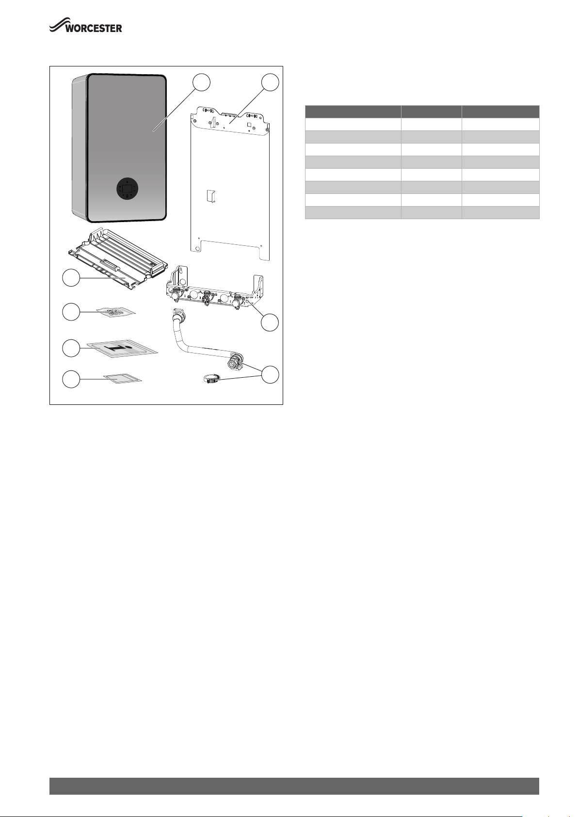
3.3 Scope of delivery
8
7
3.5 Appliance type overview
This appliance are for use with:
21
3
• Natural Gas or L.P.G. (Cat.II 2H3P type C13, C33 & C53)
This document refers to the following appliance types:
Appliance type Part number Gas Council number
GR8700iW 30 S NG 7 738 100 805 41-406-87
GR8700iW 35 S NG 7 738 100 806 41-406-86
GR8700iW 30 SB NG 7 738 100 837 41-406-83
GR8700iW 35 SB NG 7 738 100 838 41-406-82
GR8700iW 30 S LPG 7 738 100 854 41-406-89
GR8700iW 35 S LPG 7 738 100 855 41-406-88
GR8700iW 30 SB LPG 7 738 100 856 41-406-85
GR8700iW 35 SB LPG 7 738 100 857 41-406-84
Table 2 Type overview
The name of the appliance consists of the following parts:
• GR8700iW: Type name
• 30 or 35: Heat output in kW
• S: System appliance
• B: Black font panel
• NG: Gas type (Natural Gas)
• LPG: Gas type (Liquid Petroleum Gas)
3.6 Product identification
6
5
Fig. 1 Scope of delivery
[1] Wall mounted gas condensing boiler
[2] Mounting bracket
[3] Mounting plate
[4] PRV Discharge pipe (including securing clips)
[5] Guarantee card
[6] Set of printed documents for product documentation
[7] Fixing materials (screws with accessories)
[8] Lower cover
3.4 Declaration of Conformity
The design and operation of this product comply with European
Directives and the supplementary national requirements. Conformity
has been demonstrated by the CE marking.
You can ask for a copy of the declaration of conformity for this product.
For this see the contact address on the back cover of these instructions.
4
0010023673-001
Data plate
The data plate includes the product performance information, approval
data and serial number. The data plate location can be found in the
product overview.
Additional type plate
The product name and the most important product data are shown on
the additional data plate. The additional type plate can be found on the
outside of the product in an easily accessible location.
Greenstar 8000 Style – 6720883855 (2019/01)
7
Product Information
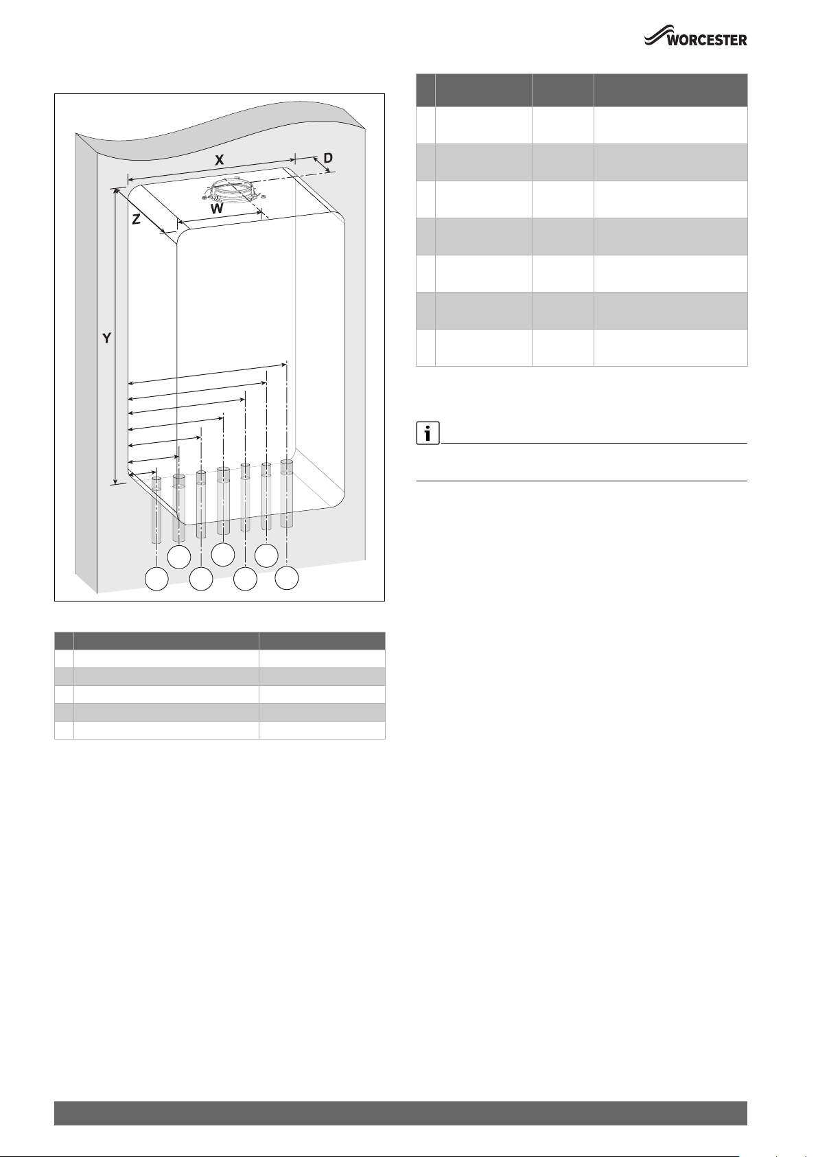
3.7 Pipe work positions and flue outlet
# Function From left
case edge
1 Condensate Outlet 58mm 22mm
2 CH Flow 90mm 22mm
3 Cylinder Return 1)155mm 15mm
4 Gas inlet 220mm 22mm
1)
5 Cylinder Flow
6 CH Return 350mm 22mm
7 PRV Discharge 384mm 15mm
1) Only available if optional integral diverter valve kit is fitted.
Table 4 Pipe dimensions
For servicing purposes, keep condensate and pressure release valve
discharge pipes away from other hydraulic components.
285mm 15mm
Diameter of pipe
• Rubber push fit connection
• Compression fitting
• Compression fitting
• Compression fitting
• Compression fitting
• Compression fitting
• Compression fitting
2
1
Fig. 2 Pipe and flue outlet dimensions
Description Dimensions (mm)
X Appliance width 440
Y Appliance height 780
Z Appliance depth 365
W Flue centre from appliance left side 220
D Flue centre from rear of appliance 87
Table 3 Appliance and flue outlet dimensions
4
3
6
5
7
0010023464-001
8
Greenstar 8000 Style – 6720883855 (2019/01)
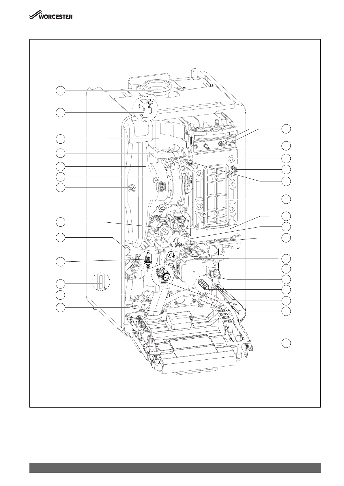
3.8 Designation of components
13
12
11
10
9
8
7
Product Information
14
15
16
17
18
19
20
6
5
4
21
22
23
24
3
25
26
2
27
1
28
29
Fig. 3 Product overview System boilers, combustion cover removed
[1] KEY accessory housing slot (wireless Gateway)
[2] Condensate trap
[3] Data plate 1
[4] Pressure sensor
[5] Pressure gauge
[6] Venturi (sealed)
Greenstar 8000 Style – 6720883855 (2019/01)
0010023657-001
[7] Schrader Valve
[8] Fan
[9] Expansion vessel
[10] Heating flow
[11] Air-gas manifold with non-return valve
[12] Ignition transformer
9

Product Information
[13] Flue
[14] Ignition electrodes
[15] Flame sensing electrode
[16] Flow temperature sensor at flow pipe
[17] Heating block temperature limiter
[18] Flow temperature sensor at heating block
[19] Inspection cover
[20] Condensate sump
[21] Gas valve
[22] Automatic air vent valve (pump)
[23] Data plate 2
[24] Diverter valve (accessory)
[25] Heating pump
[26] Drain point
[27] Pressure relief valve (heating circuit)
[28] Central heating return
[29] Control unit
3.9 Product data for energy consumption
The product data on energy consumption can be found in the operating
instructions for the user.
3.10 Standard accessories
The appliance has the option to fit an integral diverter valve kit, whichhas
multiple controls options for the use with vented and unvented hotwater
cylinders. The details can be found in the Installation Instructionsfor the
diverter valve kit.
10
Greenstar 8000 Style – 6720883855 (2019/01)
4 Pre-Installation
NOTICE:
Risk of damage to system or appliance!
Before installation
▶ All the following Pre-Installation sections must be read and
requirements met before starting appliance or flue installations.
4.1 System preparation
4.1.1 Artificially softened water
It is possible to have an ion exchange water softener fitted to the cold
water system of the property. However, the appliance requires an
untreated cold water connection taken from the mains supply, before the
water softener, to the primary water filling point of the heating system.
Alternatively there are water softening/treatment appliances that do not
adjust or alter the pH levels of the water. With these appliances it may not
be necessary to provide an untreated water by-pass to the primary water
filling point of the heat system.
NOTICE:
▶ Salt based softened water must not be used to fill the central heating
system.
4.1.2 Water systems and pipe work
Pre-Installation
Hot water:
• Taps and mixing valves must be capable of sustaining a pressure up to
10 bar.
• Hot water temperature and flow rate are affected by the size and
insulation of pipe work making up the distribution system and are
controlled by the hot water tap and the water main inlet pressure. A
mixing valve can be fitted if a more permanent temperature setting is
required.
• If using more than one outlet at once causes water flow starvation, fit
flow balancing valves or Ball-O-Fix valves to the appropriate outlets.
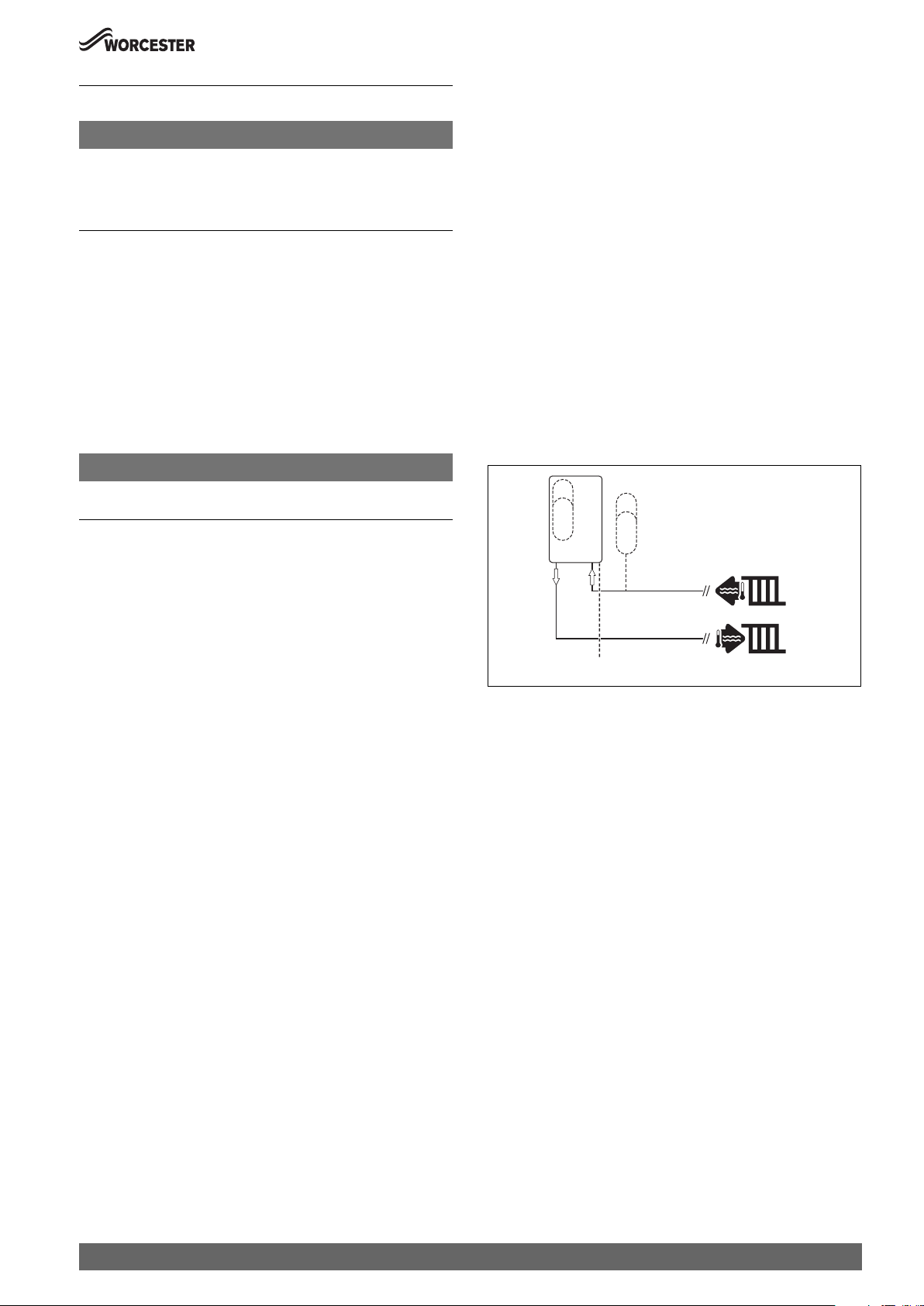
Primary system considerations - Combi & System appliances
Sealed system
• The CH sealed system must be filled using a WRAS approved filling
loop or comply with examples in 4.1.4 "System fill" section.
• Where the system volume is more than 100 litres or exceeds 2.5 bar
at maximum heating temperature an additional expansion vessel [2]
must be fitted as close as possible to the appliance in the central
heating return.
• Pressurise the extra expansion vessel [2] to the same value as the
built-in expansion vessel - refer to the Technical data page.
1
2
Primary system plastic pipework:
• Any plastic pipe work must have a polymeric barrier, complying with
BS 7921 and installed to BS 5955 with 600mm (minimum) length of
copper connected to the appliance.
• Plastic pipe work used for under-floor heating must be correctly
controlled with a thermostatic blending valve limiting the
temperature of the circuits to approximately 50°C with 1000mm
(minimum) length of copper or steel pipe connected to the
appliance.
Primary system/connections/valves:
• Do not use galvanised pipes or radiators.
• All system connections, taps and mixing valves must be capable of
sustaining a pressure of 3 bar.
• Radiator valves should conform to BS 2767:10.
• All other valves should conform to BS 1010.
• It is best practice to fit Thermostatic Radiator Valves (TRV's) to all
radiators, except the area where the room thermostat is sited which
must be fitted with lockshield valves that are left open.
• If the circulating pump speed is fixed and system circulation can be
significantly adjusted or stopped by TRV's or zone valves, a system
bypass should be installed to give at least a 3 metre circuit when
activated. However; any appliance fitted with a modulating pump
may not require a system bypass.
• Drain cocks are required at all the lowest points on the system.
• Air vents are required at all high points on the system.
3
Fig. 4 Additional expansion vessel
[1] Appliance expansion vessel
[2] Additional expansion vessel
[3] Pressure relief discharge
[4] Heating return
[5] Heating flow
4
5
0010021117-001
Showers/Bidets:
• If a shower head can be immersed in water or comes closer than
25mm from the top edge of a bath or shower tray spill-over level then
an anti-siphon appliance must be fitted to the shower hose.
• Bidets with direct hot and cold mains water can be used (with the
approval of the local water authority) and must be the over rim
flushing type with shrouded outlets to prevent the fitting of hand held
sprays.
Greenstar 8000 Style – 6720883855 (2019/01)
11
Pre-Installation
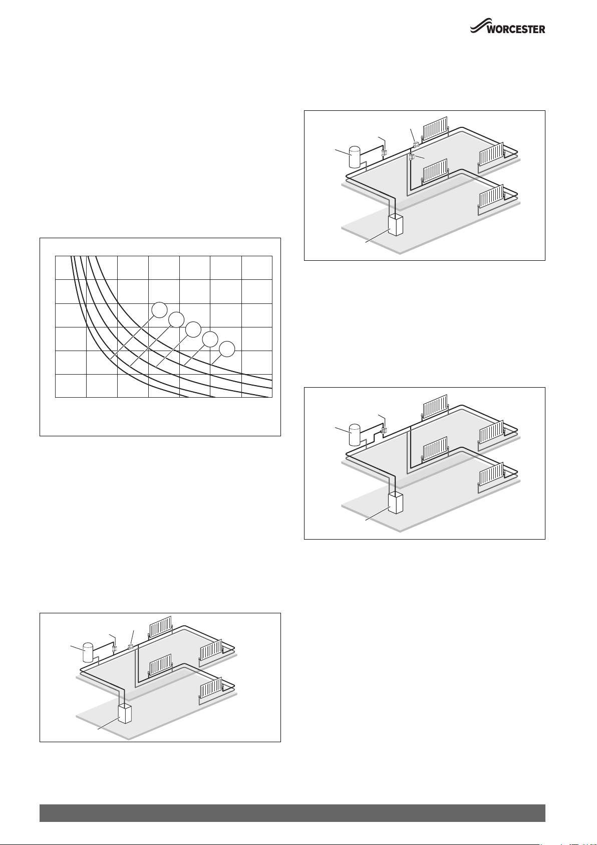
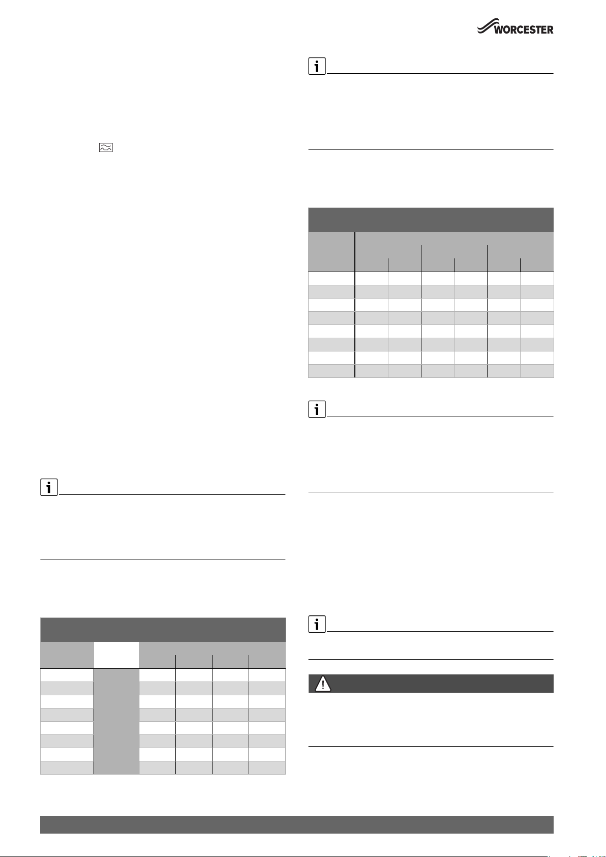
Checking the size of the expansion vessel
To determine whether an additional expansion vessel is required: Follow
the steps below:
▶ Calculate the total system volume (litres). Plotting a line vertically on
the chart ( Fig. 5).
▶ Determine the central heating maximum operating flow temprature
(73 °C for condensing). Plot a line horizontally on the chart ( Fig.
5).
▶ Determine the pre charge in the expansion vessel based on static
head, 1 meter = 0.1 bar. (default = 10 metres).
▶ Select a curve from the key below (1-5).
If the dissected lines are in area A then no additional expansion is
required.
If the dissected line is in are B then an additional expansion vessel must
be installed ( Fig. 4).
T[°C]
90
80
70
60
5
4
B
3
2
50
1
A
40
Sealed primary system - Cylinder and 2 x central heating zones:
Typical S-Plan Plus example
• The cylinder return must be the last connection on the common
return pipe to prevent reverse circulation.
2
2
3
2
1
Fig. 7 Cylinder and 2 x heating zones
[1] Appliance
[2] Zone valves
[3] Hot water cylinder
Sealed primary system - 3-way valve, cylinder and central heating
zone:
Typical Y-Plan example
• The cylinder return must be the last connection on the common
return pipe to prevent reverse circulation.
0010021230-001
30
0 100 200 300 400 500 600 700
V[l]
0010016558-002
Fig. 5 Curves for the expansion vessel
1 Pre-charge pressure 0.5 bar (minimum)
2 Pre-charge pressure 0.75 bar
3 Pre-charge pressure 1.0 bar (default setting)
4 Pre-charge pressure 1.2 bar
5 Pre-charge pressure 1.3 bar
T Maximum operating temperature [ °C]
V Total System Volume [l]
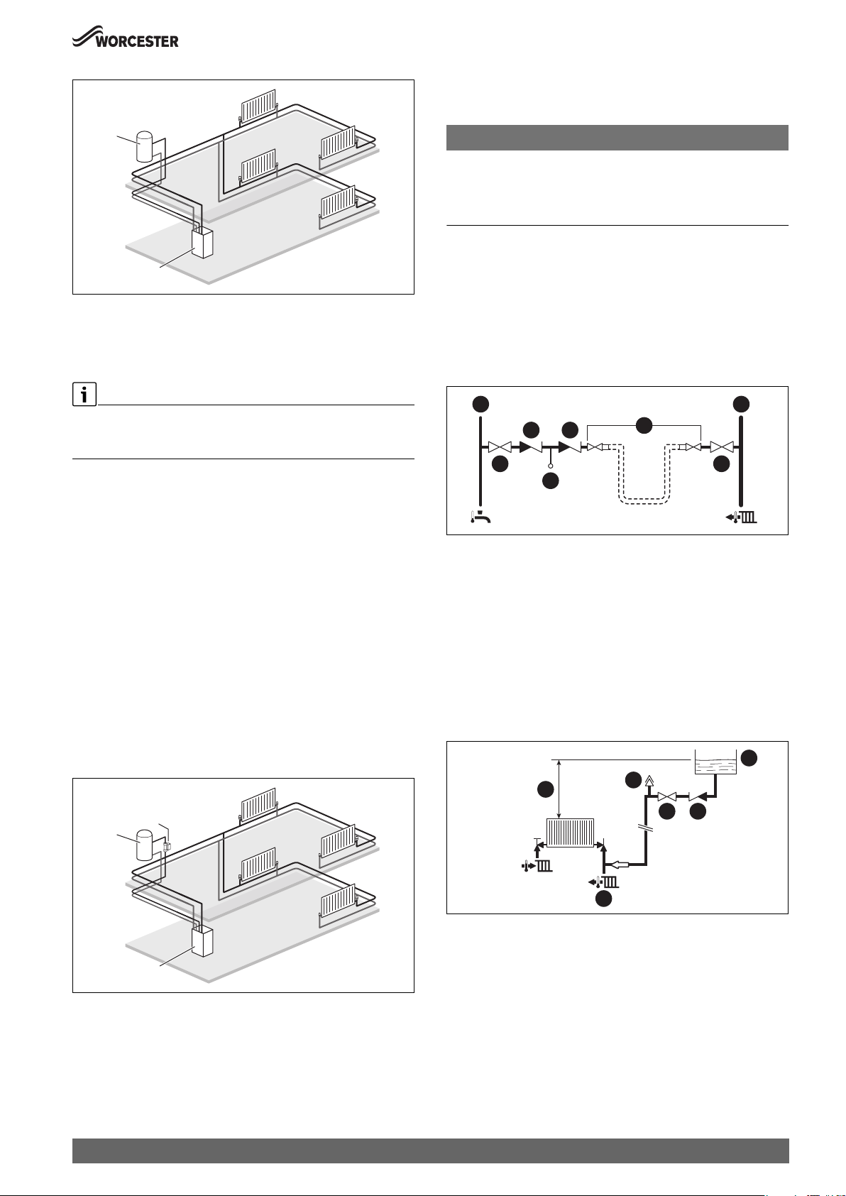
4.1.3 System layouts examples
Sealed primary system - Cylinder and central heating zone:
Typical S-Plan example
• The cylinder return must be the last connection on the common
return pipe to prevent reverse circulation.
2
2
3
2
3
1
Fig. 8 3-way valve, cylinder and heating zone
[1] Appliance
[2] 3-Way zone valve
[3] Hot water cylinder
Optional integral diverter valve kit
This appliance is designed to operate on a sealed system only. The
appliance will require to fit a separate flow and return pipe from the
water cylinder to the wall mounting frame and terminate in 15mm
copper pipe.
Details for the connection of the integral diverter valve kit components
are found within the Installation Instructions for the kit.
0010021231-001
1
Fig. 6 Cylinder and heating zone
[1] Appliance
[2] Zone valves
[3] Hot water cylinder
12
0010021229-001
Sealed primary system - Internal diverter valve kit:
• This appliance is designed to operate on a sealed system only. The
appliance will require a second flow and return pipe from the hot
water cylinder to the wall mounting frame and terminate in 15mm
copper pipe. The following system layouts show a simplified example
of the pipe configuration to the appliance.
Greenstar 8000 Style – 6720883855 (2019/01)
4.1.4 System fill
Filling primary sealed systems
Pre-Installation
3
1
0010021286-001
Fig. 9 Example layout - Internal diverter valve kit
[1] Appliance with internal diverter valve kit
[3] Unvented hot water cylinder
Unvented cylinders
In all cases the cylinder manufacturer must be contacted for
confirmation their product is suitable for the installation layout shown in
figure 9.
Although the accepted common practice of a 2-port motorised valve
installed in the primary flow pipe to the cylinder and wired to the dualthermostat supplied with the cylinder. It is possible to use the integral
diverter valve kit and not need the 2-port motorised valve to cut the flow
of heat to the cylinder to comply with Building Regulation Part G3.
• The integral diverter valve kit cylinder sensor must be used.
• The general layout (figure 9) can be used for unvented cylinder by
utilising the high limit thermal cut out of the cylinder dual-thermostat
to interrupt the permanent live to the appliance, preventing any heat
being produced from the appliance.
Example layout with unvented cylinder & cylinder safety valve.
If required by the cylinder manufacture to fit/use the cylinder safety valve
then this can also be carried out (figure 10) with the integral diverter
valve kit.
• The cylinder safety valve and dual-thermostat (control thermostat
and high limit thermal cut out) are wired to interrupt the permanent
live to the appliance, preventing any heat being produced from the
appliance.
2
3
NOTICE:
Filling the primary sealed system
The system must not be filled with salt based softened water.
▶ Ensure the primary water filling point uses an untreated cold water
connection from the mains supply, before a water softener.
• Filling the system must comply with one of the following methods
shown.
• The filling point must be at low level and must never be a permanent
connection to the mains water supply.
• Filling loops must be WRAS approved.
• If the external filling link is sited away from the appliance, then a
pressure gauge should be installed at the filling point.
External filling loop
1
3 3
5
6
22
4
0010012942-001
Fig. 11 External filling loop system fill example
[1] Cold mains inlet pipe
[2] Stop valve
[3] Check valve
[4] Test point
[5] Hose union
[6] Central heating flow pipe
Top-up tank system fill
In situations where the cold mains pressure is not sufficient to pressurise
the system to between 1 and 1.5bar an alternative can be to use a top-up
tank.
7
9
8
2 3
1
Fig. 10 Example layout - Internal diverter valve kit with unvented
cylinder and cylinder safety valve
[1] Appliance with internal diverter valve kit
[2] Cylinder safety valve (unvented cylinder)
[3] Unvented hot water cylinder
Greenstar 8000 Style – 6720883855 (2019/01)
0010021233-001
6
0010012943-001
Fig. 12 Top-up tank system fill example
[2] Stop valve
[3] Check valve
[6] Central heating flow pipe
[7] Top-up tank
[8] Automatic air vent
[9] Minimum height above the highest point of the system - 1000mm
(39 in)
13
Pre-Installation
4.2 Mains supply
4.2.1 Electrical supply
• Supply: 230V AC - 50 Hz
• This appliance must not be connected to a three phase supply.
• The wiring between the appliance and the electrical supply must
comply with the latest IET wiring regulations that apply to wiring a
fixed appliance.
• Type A RCDs must be employed where additional protection is
required.
• External 3fuse to BS1362.
• The appliance must be earthed.
• Cable: PVC insulated 0.75mm
2
(24 x 0.2mm) temperature rated to
90 °C, to BS EN50525.
• Any additional components that are connected to the appliance with
mains electrical supply must not have a separate supply.
• Additional equipment wired to the appliance must comply with the
latest IET wiring regulations.
• Appliance IP rating - IPX4D
4.2.2 Gas supply
• Appliances using Natural Gas (NG) must be connected to a governed
meter.
• Appliances using Liquid Petroleum Gas (LPG) must be connected to
a regulator.
• Installation and connection of the gas supply to the appliance must
be in accordance with BS6891.
• Gas pipe sizing should be calculated to ensure no more than the
permitted mbar drop between the meter/governor to the appliance
inlet. ( chapter 12.8).
• The meter or regulator and pipe work to the meter or regulator must
be checked, preferably by the gas supplier. This is to ensure that the
equipment is in good working order and can meet the gas flow and
pressure requirements, in addition to the demand from any other
appliance being served.
Pipe sizing (NG & LPG)
Natural Gas:
▶ When using this table to estimate the gas flow rate in pipe work of a
known length, the effective length will be increased by 0.5m for each
90° elbow and tee fitted and by 0.3m for each 90° bend. This method
is only a estimate - for more complex design please refer to BS6891
2015 and training given in ACS.
Liquid Petroleum Gas (LPG):
Discharge rates for copper tube with 2.5mbar differential pressure
between the ends for LPG.
Discharge rates for LPG (m3/hr & kW)
with straight horizontal copper tube
Tubing Outside diameter
Length (m) 15mm 22mm 28mm
kW m3/hr kW m3/hr kW m3/hr
3 38.4 1.49 207 8.01 412 15.92
6 26.1 1.01 135 5.21 230 8.86
9 20.5 0.79 108 4.19 215 8.33
12 17.9 0.70 94 3.62 187 7.25
15 15.5 0.60 82 3.20 168 6.51
18 13.5 0.53 74 2.86 145 5.61
21 12.9 0.50 67 2.58 135 5.24
24 12.0 0.47 61 2.58 126 4.87
Table 6 Liquid Petroleum Gas (LPG)
Liquid Petroleum Gas (LPG):
▶ When using this table to estimate the Gas flow rate in pipe work of a
known length, the effective length will be increased by 0.6m for each
90° elbow or tee and by 0.3m for each 90° bend or straight coupler.
This method is only a estimate - for more complex design please refer
to BS6891 2015 and training given in ACS.
Gas pipe work:
▶ Gas installation pipe work must be designed to ensure the pressure
loss between the meter outlet (NG) or storage and regulator (LPG)
and the inlet to each appliance does not exceed 1mbar (NG) 2.5mbar
(LPG) table ”Allowed mbar pressure drop”.
Natural Gas (NG):
Discharge rates for copper tube with 1mbar differential pressure
between the ends for Natural Gas.
Discharge rates for Natural Gas (m3/hr)
with straight horizontal copper tube
Pipe Pipe Size (mm)
Length (m) 15 22 28 35
3
2.9 8.7 18 32
6 1.9 5.8 12 22
9
1.5 4.6 9.4 17
12 Discharge 1.3 3.9 8 15
15
m3/hr 1.1 3.4 7 13
20 0.95 2.9 5.9 11
25
0.92 2.5 5.2 9.5
30 0.88 2.3 4.7 8.5
Table 5 Natural Gas
4.3 Appliance location and clearances
4.3.1 Appliance location
• Follow local regulations for the location within the property that the
appliance is to be installed.
• This appliance is only suitable for installing internally within a
property at a suitable location onto a flat, fixed rigid surface capable
of supporting the appliance weight.
• The appliance is not suitable for external installation.
No surface protection is required againat heat transfer from the
appliance
DANGER:
Danger from explosive and flammable materials:
Storage of explosive and flammable materials.
▶ Do not store flammable materials (paper, curtains, clothing, primer,
paint, …) in proximity to the appliance.
14
Greenstar 8000 Style – 6720883855 (2019/01)
Pre-Installation
NOTICE:
Damage to appliance:
Contaminated combustion air.
▶ Do not use any cleaners containing chlorine or hydrogen halide (i.e.
spray cans, primers, cleaners, paint and glue).
▶ Do not store or use these substances in the appliance, room.
▶ Avoid the build up of dust.
NOTICE:
Damage to appliance:
Extreme temperatures may cause damage to the heating system.
▶ Ensure the ambient temperature is above 0 °C and below 35 °C.
NOTICE:
Damage to system:
The heating system pipe work can be damaged by frost if installed in an
internal unheated area, such as a loft, basement or garage.
The appliance internal frost protection only monitors the system water
temperature within the appliance to provide protection for the
appliance.
▶ Install a frost thermostat and pipe thermostat connected in series, to
protect the system pipe work.
We recommend that the frost thermostat is sited in the coldest
unheated area in which pipe work is located and that it is set to call for
heat at 5 °C. The Pipe stat should be located on whichever pipe is
furthest from the heated area where warmer water will be drawn from
considering the direction of flow, and set to end the demand at 15 °C.
▶ The system pipe work in the internal unheated area should be
insulated.
▶ If the appliance is to be shut down for an extended period, drain the
central heating system.
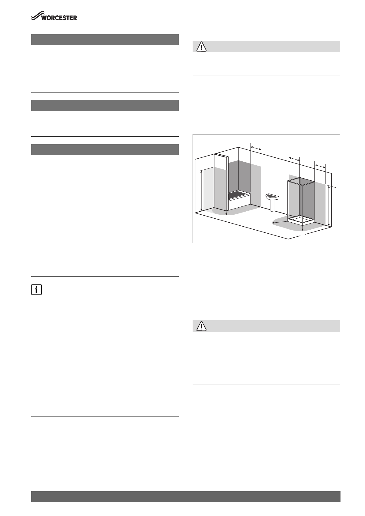
4.3.2 Rooms containing a bath or shower
CAUTION:
Risk of electric shock
▶ Any switch or appliance control using mains electricity must not be
within reach of a person using the bath or shower.
• In all cases the installation must be in accordance with the latest
amendments to the latest edition of the IET Wiring Regulations
(BS7671).
• Check the IP rating of any control units to be used on this appliance.
• Circuit breaking appliances should be used in accordance with the
regulations.
• Figure 13 is for guidance only.
600mm
600mm
600mm
1
1
2*
2250mm
2*
A
2
2
1
2
A
A
0010017086-001
Fig. 13 Bathroom installations
[1] Zone 1
[2] Zone 2
[2*] Without the end wall, zone 2 must extend 600mm from the bath
[A] 600mm radius from the bath or shower
2250mm
The appliance must be installed where:
▶ The area is well lit, allowing to clearly see the appliance to carry out
any work or checks.
▶ An engineer can gain clear and safe access to work on the product or
component, including making adequate provision for visual
inspection of flues in voids.
▶ The homeowner can gain clear and safe access to the controls, check,
top up or reset the appliance.
▶ Roof space installations must fully conform to BS 5410 part 1: roof
space installations.
▶ Products in roof spaces must have permanent fixed lighting, a
permanent fixed retractable ladder and a fixed floor area sufficient to
allow access for normal use and servicing around the product and
between and the access hatch.
We would also recommend that a remote pressure gauge and filling
loop are sited where the customer can gain easy access for checking
and topping up.
4.3.3 Appliance clearances
Appliance clearances
• The following details covering the installation, service and
maintenance clearances for the appliance.
CAUTION:
Risk of damage to appliance or property
The appliance will overheat if the clearance space around the appliance
is restricted by objects.
▶ Do not restrict this space with the addition of cupboards, shelves etc.
next to or around the appliance.
▶ Do not store any combustible materials on or next to the appliance,
such as clothes, towels, paper or plastic bags.
Greenstar 8000 Style – 6720883855 (2019/01)
15
Pre-Installation
0010012940-001
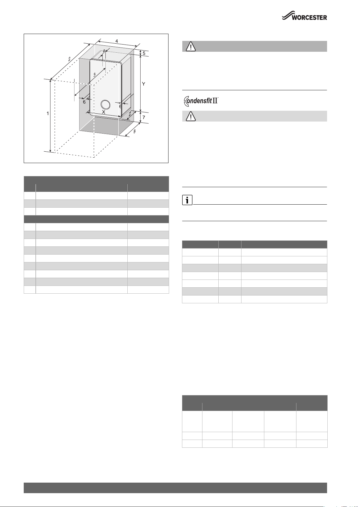
Fig. 14 Appliance minimum clearances
Minimum clearances
Description Dimensions (mm)
X Appliance width 440
Y Appliance height 780
Z Appliance depth 365
Installation/Maintenance
1 Overall clearance height 1,150/1,190 *
2 Overall clearance depth 965
3 In front of appliance 600
4 Overall clearance width 450
5 Above the appliance 170/210 *
6 Either side of appliance 5
7 Below the appliance 200
8 Compartment depth 385
9 Appliance to removable door 20
Table 7
[*] Height for either 60/100 flue or 80/125 flue
Appliances in compartments
Follow the latest requirements of BS6798 and BS5440 and note:
• Minimum clearances must be maintained.
• An access door is required to install, service and maintain the
appliance and any ancillary equipment.
• If the appliance is installed in an unventilated airing/storage
cupboard, there is no requirement to make a partition between the
appliance and the storage space as long as the minimum clearances
around the appliance are maintained.
4.4 Flue systems considerations
WARNING:
Flue systems
Possible flue gas escape
▶ Use Worcester, Bosch Group approved Condensfit II flue systems
only, no other manufacturer’s flue have been tested or approved for
use with Worcester, Bosch Group appliances.
CAUTION:
Concealed flue systems:
▶ Where a flue system is going to be concealed, provision must be
made for service and inspection.
▶ Voids containing concealed flues must have at least one inspection
hatch no less than 300mm square.
▶ Flue joints within the void must not be more than 1.5 metres from the
edge of the inspection hatch.
▶ Inspection hatches should be located at changes of direction.
▶ If this is not possible, bends should be viewable from both directions.
Refer to the manual supplied with the Worcester, Bosch Group flue kit for
complete installation instructions.
Flue kit part numbers
Part number Flue Ø Description
7 738 112 869 60/100 Telescopic horizontal flue kit (Silver)
7 716 191 082 60/100 Telescopic horizontal flue kit
7 716 191 171 60/100 Extended telescopic horizontal flue kit
7 733 600 048 60/100 Horizontal high level telescopic flue kit
7 719 003 702 80/125 Telescopic horizontal flue kit
7 719 002 430 60/100 Vertical balanced flue kit
7 719 002 431 80/125 Vertical balance flue kit
Table 8 Flue kit assembly part numbers
4.4.1 Flue length
The maximum flue length will depend on the following factors:
• 60/100mm flue system
– Vertical/horizontal flue type
– Appliance output
– Plume management length
• 80/125mm flue system
– Vertical/horizontal flue type
– Appliance output
16
Horizontal maximum flue lengths
Maximum horizontal flue lengths (L)
Output 60/100 80/125
No Plume
management
+ 500mm
of plume
management
+4500mm of
plume
management
No plume
management
available
35kW 10,000mm 10,000mm 7,200mm 29,000mm
30kW 17,000mm 17,000mm 14,200mm 25,000mm
Table 9 Maximum flue lengths - Horizontal flues
Greenstar 8000 Style – 6720883855 (2019/01)
Pre-Installation
Vertical maximum flue lengths
Flue length [L] Flue length [L]
Output 60/100 80/125
35kW 14,000mm 29,000mm
30kW 21,000mm 25,000mm
Table 10 Maximum flue lengths - Vertical flues
Flue system bends
NOTICE:
Effective flue lengths of bends:
Each bend used has an equivalent straight flue length.
▶ Refer to the table below.
Effective flue length
Bend 60/100 80/125
45° 0.5m 0.5m
90° 1.5m 1.5m
Table 11 Effective length of bends
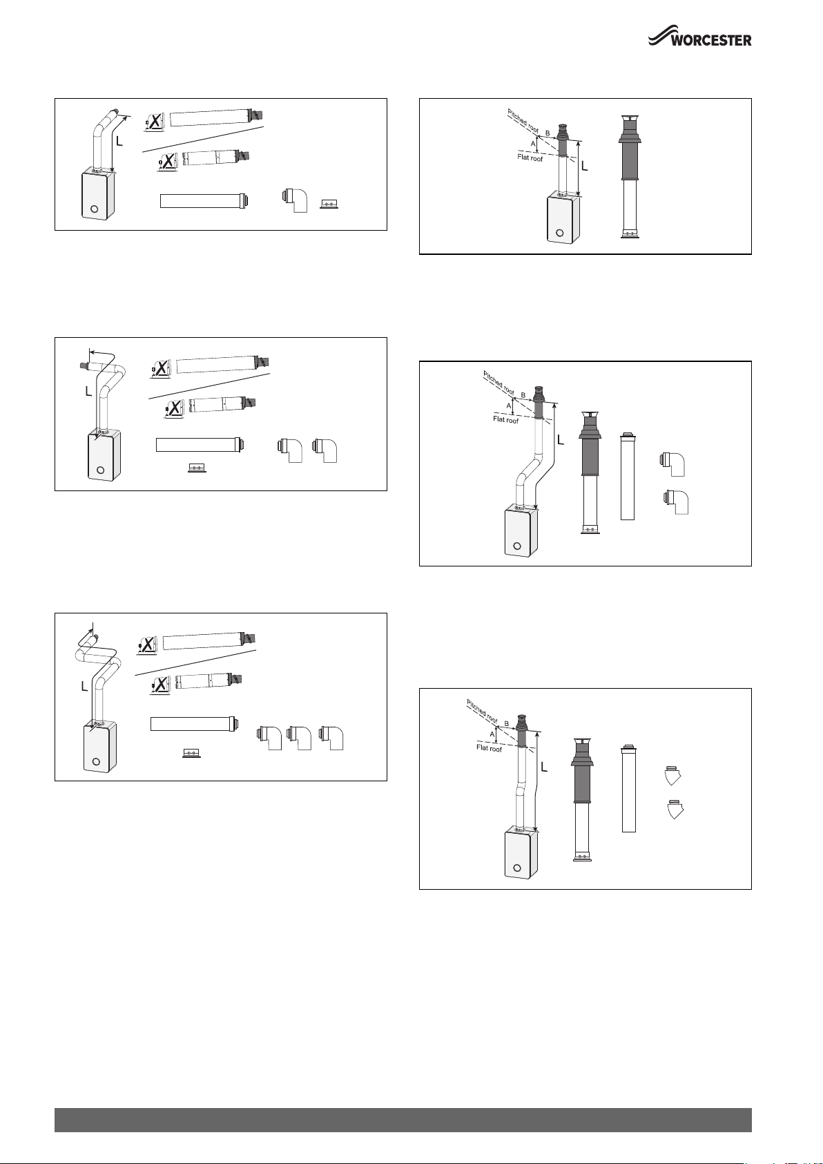
4.4.2 Flue options
The systems have diiferent maximum flue lengths, refer to the following
example flue options for those maximum flue lengths.
Horizontal high level flue assembly
60/100 mm
383 mm - 603 mm
Horizontal fixed length flue assembly
1050 mm
330 mm Min
0010015192-001
Fig. 17 Horizontal flue option
• Flue length [L] (adaptor bend included in length calculation)
– 60/100 = 330 - 1,050mm
– 80/125 = N/A
Extended horizontal flue
0010015193-001
Fig. 18 Horizontal flue option
• Flue length [L] (adaptor bend included in length calculation)
– Maximum flue length as stated in "Horizontal maximum flue
lengths".
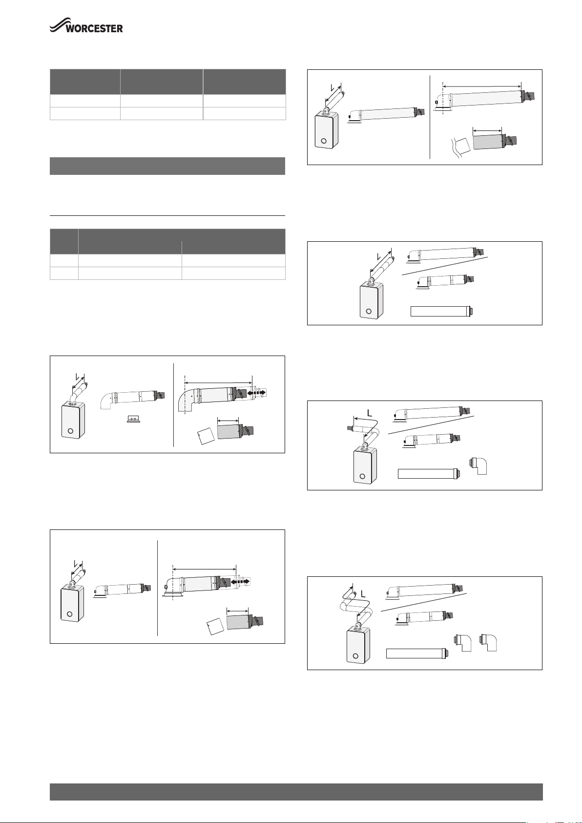
Horizontal flue with additional 90° elbow
130 mm Min
Fig. 15 Horizontal flue option
• Flue length [L] (initial bend included in length calculation)
– 60/100 = 202 - 603mm
– 80/125 = N/A
Telescopic horizontal flue assembly
60/100 mm
[A] 350 mm - 570 mm
[B] 570 mm - 790 mm
130 mm Min
Fig. 16 Horizontal flue option
Telescopic horizontal flue assembly [A]
• Flue length [L] (adaptor bend included in length calculation)
– 60/100 = 180 - 570mm
– 80/125 = 405 - 600mm
Extended telescopic horizontal flue assembly [B]
• Flue length [L] (adaptor bend included in length calculation)
– 60/100 = 570 - 790mm
– 80/125 = N/A
0010015190-001
0010015194-001
Fig. 19 Horizontal flue option
• Flue length [L] (adaptor bend included in length calculation)
– Maximum flue length as stated in "Horizontal maximum flue
lengths" minus the 90° bend equivalent straight flue length as
stated in Table 11 "Effective length of bends".
Horizontal flue with additional 90° elbows
0010015191-001
0010015195-001
Fig. 20 Horizontal flue option
• Flue length [L] (adaptor bend included in length calculation)
– Maximum flue length as stated in "Horizontal maximum flue
lengths" minus 2 x 90° bends equivalent straight flue length as
stated in Table 11 "Effective length of bends".
Greenstar 8000 Style – 6720883855 (2019/01)
17
Pre-Installation
A
A
A
High level horizontal flue
Fig. 21 Horizontal flue option
• Flue length [L] (initial bend included in length calculation)
– Maximum flue length as stated in "Horizontal maximum flue
lengths".
High level horizontal flue with additional 90° elbow
0010015196-001
0010015197-001
Vertical balanced flue assembly
= 300 mm
B = 500 mm
0010015199-001
Fig. 24 Vertical flue option
• Flue length [L]
– Maximum flue length as stated in "Vertical maximum flue
lengths".
Vertical balanced flue with 90° elbow offset
Fig. 22 Horizontal flue option
• Flue length [L] (initial bend included in length calculation)
– Maximum flue length as stated in "Horizontal maximum flue
lengths" minus the 90° bend equivalent straight flue length as
stated in Table 11 "Effective length of bends".
High level horizontal flue with additional 90° elbows
Fig. 23 Horizontal flue option
• Flue length [L] (initial bend included in length calculation)
– Maximum flue length as stated in "Horizontal maximum flue
lengths" minus 2 x 90° bends equivalent straight flue length as
stated in Table 11 "Effective length of bends".
= 300 mm
B = 500 mm
0010015200-001
Fig. 25 Vertical flue option
• Flue length [L]
– Maximum flue length as stated in "Vertical maximum flue lengths"
minus 2 x 90° bends equivalent straight flue length as stated in
Table 11 "Effective length of bends".
Vertical balanced flue with 45° elbow offset
0010015198-001
= 300 mm
B = 500 mm
0010015201-001
Fig. 26 Vertical flue option
• Flue length [L]
– Maximum flue length as stated in "Vertical maximum flue lengths"
minus 2 x 45° bends equivalent straight flue length as stated in
Table 11 "Effective length of bends".
18
Greenstar 8000 Style – 6720883855 (2019/01)
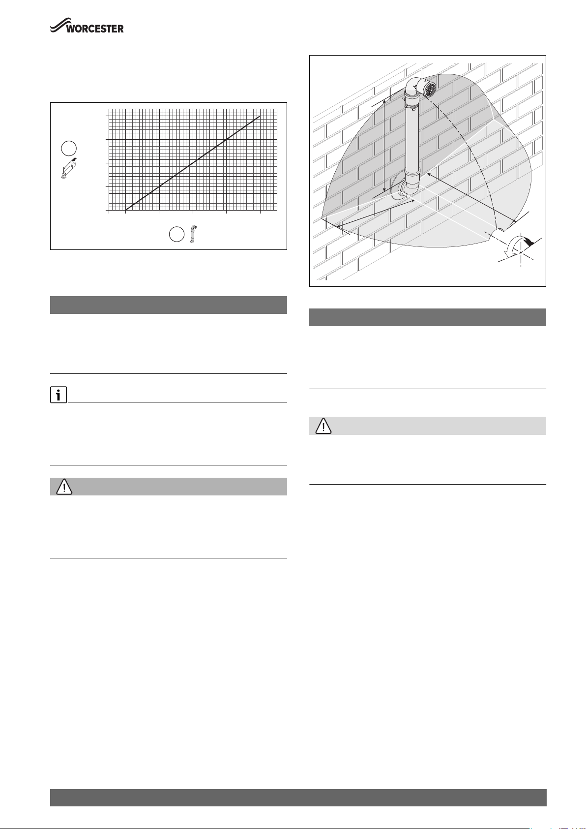
4.4.3 Plume management system
For every extra 1000mm of plume management after the first 500mm,
the internal 60/100 flue length must be reduced by 700mm, up to a
maximum of 4500mm of plume management.
2,800
2,100
1
1,400
Pre-Installation
m
m
00
5
[mm]
700
0
500 1,500 2,500 3,500 4,500
[mm]
2
0010023114-001
Fig. 27 Reduction to flue length as plume length increases graph
[1] Reduction to flue length [mm] (maximum reduction 2,800mm)
[2] Plume length [mm] (maximum plume length 4,500mm)
NOTICE:
Plume management length:
▶ The plume management length must be a minimum of 500mm and
must not exceed the maximum straight length for a horizontal Ø 60/
100mm flue with a 60mm plume management system as stated
previously.
Horizontal plume management runs
▶ The initial horizontal run from the terminal elbow must have a
minimum 10° fall back, (stop tabs in the elbow prevent less than 10°)
to the appliance for proper disposal of condensate.
▶ Any further horizontal runs after an elbow can be 3°.
WARNING:
Minimum plume management length:
The minimum distance of 500mm must be maintained between air inlet
and exhaust.
▶ Do not terminate the plume management inside the terminal
exclusion zone (shaded area) shown in figure 28.
5
0
0
m
m
mm
00
5
±80°
0010013548-001
Fig. 28 Terminal exclusion zone
NOTICE:
Cutting the 500mm pipe
If the 500mm plume management pipe kit is cut, an additional elbow will
be required to join the pipe work.
▶ The Plume management extension kit contains the components
required for such a configuration.
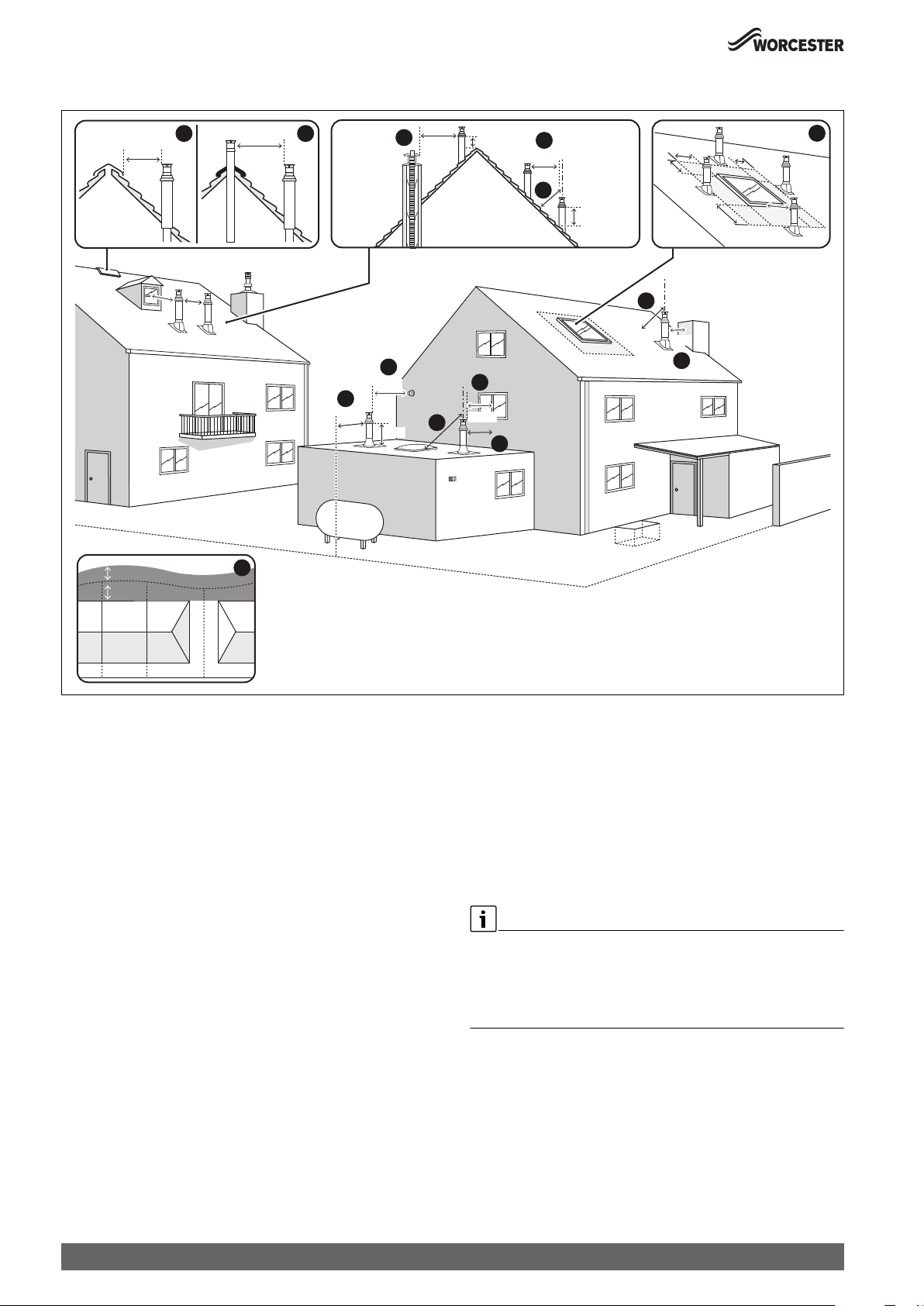
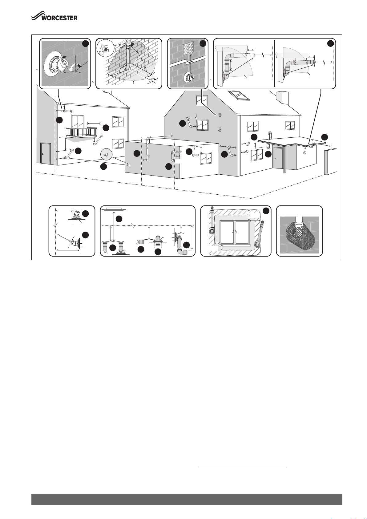
4.4.4 Flue terminal positions
CAUTION:
Flue terminal positions
▶ All measurements are the minimum clearances required.
▶ Terminals must be positioned so to avoid combustion products
entering the building.
Greenstar 8000 Style – 6720883855 (2019/01)
19
Pre-Installation
Vertical flue terminal positions
1/2
1/2
1500
1500
RIDGE FLUERIDGE VENT
1
600
BOUNDARY LINE
BOUNDARIES
9
1500
2
3
300
8
1200
300
2
1500
4
600
300
1
1500
500
2
600
400
7
300
5
400
600
600
7
500
5
2000
600
1500
6
Fig. 29 Vertical flue terminal positions
Key to figure 29:
[1] 1,500mm measured horizontally between a vertical flue terminal
and an opening or vented window. 500mm measured horizontally
between a vertical flue terminal and an opening or vented window
providing the flue terminal is at least 300mm above the opening.
[2] Minimum clearance to an additional flue, 600mm to a room
sealed flue or 1,500mm to an open flue.
[3] 300mm clearance from a vertical flue terminal adjacent to a
boundary line, unless it will cause a nuisance. BS 5440: Part 1
recommends that care is taken when siting a terminal in relation to
boundary lines.
[4] 600mm minimum clearance measured from an opening or vented
skylight to a vertical flue terminal. If the terminal is within
1,500mm of the opening or vented skylight then it must be at
least 300mm above the opening.
[5] 500mm clearance measured horizontally from a vertical flue to a
vertical structure.
[6] The flue must not penetrate the roof in the shaded area.
The terminal must be at least 1500mm from the opening or vent
when sited below the window or 600mm when sited to either side
or above.
0010021441-001
[7] 400mm measured diagonally from a pitched roof or 500mm in
regions with heavy snow fall. 300mm measured vertically from
the air intake to the closest intersection with the roof.
[8] 1,200mm separation between a vertical flue measured
horizontally and a horizontal flue terminal.
Not required if the horizontal flue is 1,200mm above.
[9] For the purpose of determining suitable flue terminal positions for
gas appliances, the boundary can be considered to extend to the
centre line of any adjacent routes or waterways e.g. paths,
streets, rights of way, canals, rivers or railways.
Note:
▶ Where a vertical flue terminates in an area that is enclosed on 3 sides,
the flue must be no more than 1,000mm below the lowest roof line.
You must ensure that all clearances are maintained and that products
of combustion disperse safely from the area.
20
Greenstar 8000 Style – 6720883855 (2019/01)
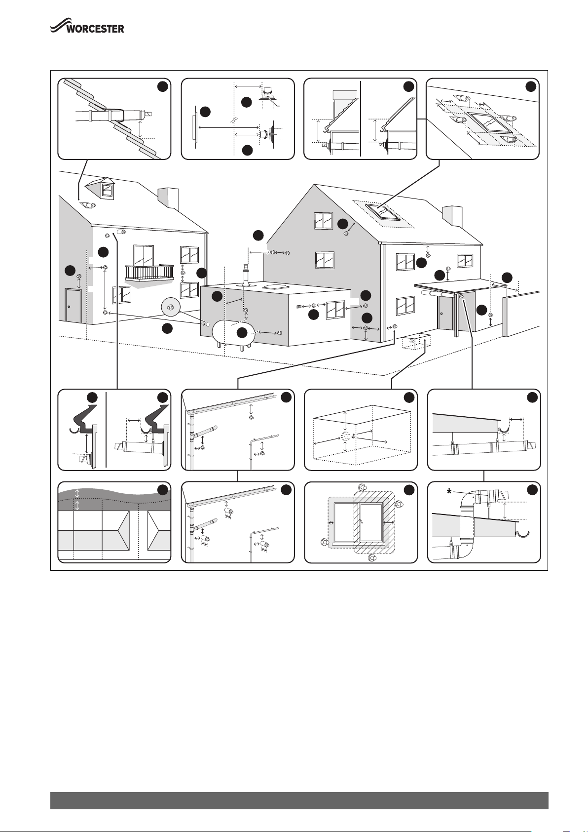
Horizontal flue terminal positions
Pre-Installation
11
300
300
1500
300
10
BOUNDARY LINE
OPENING
OPPOSITE
14
2000
300
3
600
TOP
TOP
600
600
SKYLIGHTDORMA
6
600
600
600
1500
6
5
1
600
200
300
10
200
1
10
300
7
5
600
10
25
300
300
8
600
13
1200
300
1000
300
300
300
11
3
300
11
300
5
1200
4
BOUNDARY LINE
200
1/2
1/2
1
100
BOUNDARIES
2
200
25
75
25
75
25
9
25
100
25
25
100
25
25
100
Fig. 30 Horizontal flue terminal positions
Key to figure 30:
[1] 200mm below eaves and 75mm below gutters, pipe and drains.
[2] The dimension below eaves, gutters, pipes and drains can be
reduced to 25mm, as long as the flue terminal is extended by
100mm past any overhang. The telescopic flue joint must be
sealed with suitable silicone sealant if it is external to the building.
[3] 300mm adjacent to a boundary line, unless it will cause a
nuisance. BS 5440: Part 1 recommends that care is taken when
siting terminal in relation to surfaces or boundary lines.
[4] 1,200mm separation measured between terminals facing each
other.
[5] 600m distance to a surface or boundary line facing a terminal,
unless it will cause a nuisance. BS 5440: Part 1 recommends that
care is taken when siting terminal in relation to surfaces or
boundary lines.
1
BELOW GROUND OPEN LIGHT WELL
<1000
300
300
300
2
12
600
15
300150
[6] The terminal must be at least 1500mm from the opening or vent
when sited below the window or 600mm when sited to either side
or above.
[7] 600mm diagonally to an opening door, air vent or opening
window.
[8] 1,200mm separation between a vertical flue measured
horizontally and a horizontal flue terminal.
Not required if the horizontal flue is 1,200mm above.
[9] For the purpose of determining suitable flue terminal positions for
gas appliances, the boundary can be considered to extend to the
centre line of any adjacent routes or waterways e.g. paths,
streets, rights of way, canals, rivers or railways.
[10] 300mm to an internal or external corner. 300mm above a
surface, such as the ground/ floor level or roof surface.
* If the terminal section is less than 150mm and has two screws
securing it to the elbow, the terminal section will not require a
supporting bracket.
16
100
25
10
300
0010021442-001
Greenstar 8000 Style – 6720883855 (2019/01)
21
Pre-Installation
[11] 300mm above, below and either side of an opening door, air vent
or opening window.
[12] Below ground level in an open lightwell. The flue must be at least
600mm from the opposing surface and have at least 300mm
clearance either side and below. The flue terminal must be no
more than 1000mm from the top of the lightwell.
[13] Flues should clear any LPG storage by 1,000mm horizontally and
300mm above.
[14] Proximity of flue duct outlet to boundaries, 2000mm distance to
an opening in adjacent building facing a terminal. BS 5440: Part
1 recommends that care is taken when siting terminal in relation
to boundary lines.
[15] 300mm from an opening or vented window, 150mm to a fixed
unvented window.
[16] The dimension below eaves, balconies and car ports can be
reduced to 25mm, as long as the flue terminal is extended to clear
any overhang. The telescopic flue joint of the terminal must be
sealed with suitable silicon sealant if it is external to the building.
Note:
▶ Installations in car ports are not recommended.
▶ The flue cannot be lower than 1,000mm from the top of a light well
due to the build up of combustion products.
▶ Dimensions from a flue terminal to a fanned air inlet to be determined
by the ventilation equipment manufacturer.
▶ A flue terminal guard shall be fitted whenever a terminal or air inlet is
fitted less than 2,000mm above ground, above a balcony or above a
flat roof to which people have access.
4.4.5 Plume re-direct and plume management terminal positions
Maximum and minimum plume management lengths:
▶ A minimum distance of 500mm must be maintained between the
plume management outlet and the flue air intake.
▶ The maximum plume management length is 4.5 metres for the
appliances detailed on the front of this manual.
▶ The 45° bend is equivalent to 0.5 metres of straight plume
management and the 90° bend is equivalent to 1.0 metres.
NOTICE:
▶ All measurements are the minimum clearances required.
▶ Refer to “Horizontal flue terminal positions” for all concentric flue
terminal positions unless the flue position is specified in figure 31
“Plume re-direct and plume management terminal positions”.
▶ Terminals must be positioned so to avoid combustion products
entering the building.
▶ Support the flue at approximately one metre intervals and at a change
of direction, use suitable brackets and fittings.
22
Greenstar 8000 Style – 6720883855 (2019/01)
Pre-Installation
180°
200
300
2
200
300
150
300
600
BOUNDARY LINE
300
±80°
9
1
200
150
1200
BOUNDARY LINE
2
TOP
3
TOP
±45°
11
12
2000
600
0
0
5
0
5
6
5
5
0
0
EXCLUSION ZONE
8
OPENING
OPPOSITE
300
7
TOP
0
±80°
600
300
300
BOUNDARY LINE
6
600
5
600
300
10
10
300
150
1,500
150
4
300
1500
300
13
≥140
0
0
≥5
EXCLUSION ZONE
25
25
150
100
14
200
600
15
300
100
00
≥5
EXCLUSION ZONE
7
10
300
150
TOP
8
300
9
150
FLUE TERMINAL GUARD
7 716 191 176
0010021676-001
Fig. 31 Plume re-direct and plume management terminal positions
Key to figure 31 - Plume re-direct terminal positions:
[1] This feature allows some basic plume re-direction options on a
standard telescopic horizontal flue terminal.
300mm minimum clearances to a opening e.g. window.
However the minimum clearances to an opening in the direction
that the plume management is facing, must be increased to
1,500mm.
Where the flue is less than 150mm to a drainpipe and plume
redirection is used the deflector should not be directed towards
the drainpipe.
[2] 300mm adjacent to a boundary line, unless it will cause a
nuisance. BS 5440: Part 1 recommends that care is taken when
siting terminal in relation to surfaces or boundary lines.
[3] Where the flow of products of combustion is not at right angles to
the boundary, the 600mm dimension may be measured in the
direction of flow as long as the terminal is not less than 300mm
from the boundary.
[4] When redirecting the flue discharge the terminal end must be at
least 1,500mm from any opening in the direction of the discharge
to prevent combustion products from entering the building.
Key to figure 31 - Plume management terminal positions:
[5] 600mm distance facing a surface or a boundary line, unless it will
cause a nuisance. BS 5440:Part 1 recommends that care is taken
when siting a terminal in relation to surfaces or boundary lines.
[6] Proximity of flue duct outlet to boundaries, 2000mm distance to
an opening in adjacent building facing a terminal. BS 5440: Part
1 recommends that care is taken when siting terminal in relation
to boundary lines.
[7] 300mm adjacent to a boundary line, unless it will cause a
nuisance. BS 5440: Part 1 recommends that care is taken when
siting terminal in relation to surfaces or boundary lines.
[8] 300mm distance from a boundary line to the air intake as long as
the exhaust terminal faces away from the boundary line. The
exhaust terminal must have a minimum 300mm clearance to a
surface below and there must be at least 600mm clearance when
measured horizontally in a straight line from the exhaust terminal
to any other surface.
[9] Plume Management kit air intake can be reduced to 150mm
providing the flue exhaust outlet is no less than 300mm adjacent
to a boundary line.
[10] Above, below and either side of an opening door, air vent or
opening window.
Using a Plume Management kit the air intake measurement can be
reduced to 150mm providing the flue exhaust outlet has a
300mm clearance.
[11] Below balcony or overhange. The air intake clearance can be
reduced to 150mm providing the flue exhaust outlet has a
200mm clearance.
[12] 1,200mm between terminals facing each other
1)
.
[13] Internal/external corners. The air intake clearance can be reduced
to 150mm providing the flue exhaust outlet has a 300mm
clearance.
[14] Clearances no less than 200mm from the lowest point of the
balcony or overhang.
[15] If a plume management kit is installed within the confines of a
carport or other covered, partially enclosed extension, then the
1) 600mm in case two plume management kits are used on opposing terminals.
Each terminal should use a minimum length of 500mm plume management.
Greenstar 8000 Style – 6720883855 (2019/01)
23
Pre-Installation
exhaust terminal must be positioned at least 1200mm away from
any opening into the building which is sited within the footprint of
the carport.
If the exhaust terminal is extended at least 300mm beyond the
footprint of the carport then the distance from the terminal to an
opening within the carport can be reduced to 600mm.
The exhaust terminal can also be routed though the roof of the
carport providing 25mm clearance is provided around the flue
pipe to any flammable material and that it extends at least 300mm
above the roof.
The air intake must have a minimum 150mm clearance to any
opening in the building in order to ensure the integrity of the
structure is maintained. If the exhaust terminates within the
footprint of the carport then the carport must have at least 2 sides
completely open. If the exhaust terminates at least 300mm
beyond the footprint of the carport then the carport must have at
least one completely open side. The exhaust terminal must be
positioned to ensure that plume will not cause nuisance or
damage to vehicles and that minimum clear distances in front of
the terminal will not be impeded by vehicles.
Note:
▶ Installations in car ports are not recommended.
▶ The flue cannot be lower than 1,000mm from the top of a light well
due to the build up of combustion products.
▶ Dimensions from a flue terminal to a fanned air inlet to be determined
by the ventilation equipment manufacturer.
▶ Plume kits running horizontally must have at least a 3° fall back to the
appliance for proper disposal of condensate, except or the initial
horizontal run from the terminal.
The initial plume kit horizontal run will have at least a 10° fall back to
the appliance, due to the terminal elbow design, for proper disposal
of the condensate.
4.5 Condensate discharge
Full details on condensate discharge.
▶ Follow the latest version of BS6798 and HHIC guidance.
For correct installation and trouble free operation of the appliance the
following advice should be followed:
1. To minimize the risk of freezing, wherever possible: the
condensate drain should be installed internally.
2. All condensate pipe work must ‘fall’ from the appliance by a minimum
of 3° (52mm per metre) to ensure adequate condensate flow.
3. The pipe work route must allow air to be supplied back to the
appliance for correct operation.
4. Connection to a rainwater down pipe must include an air break.
Also:
• The condensate pipe work connected to the condensate drain outlet
on the appliance should have a minimum internal diameter (ID) of
19mm.
• Keep external pipe work as short as possible and do not exceed 3
metres length.
Unless there is no means of routing the pipe internally. Further
precautions against freezing must be taken if external pipe runs
exceed 3m.
• External pipe work should have a minimum internal diameter (ID) of
30mm.
• Minimise the number of bends and connectors.
• Remove burrs after cutting pipe.
• Remove surplus solvent from the interior of the pipe.
• The condensate pipe work shall be run in standard drainpipe
material, e.g. poly(vinyl chloride) (PVC), unplasticized (vinyl
chloride) (PVC-U), acrylonitrilebutadiene.styrene (ABS),
polypropylene (PP) or chlorinated poly(vinyl chloride) (PVC.C).
4.5.1 Appliance siphonic condensate trap
The appliance has a large capacity condensate trap reducing the risk of
condensate discharge pipe work freezing up in prolonged cold
temperatures.
The expanded siphonic operation discharges every 10 to 20 minutes.
Resulting in:
• Increased velocity and flow rate.
• With less frequent siphonic actions per hour, the condensate pipe
work is empty for longer.
• Significantly reducing freezing potential for a 48 hour period at 15 °C, provided the installation parameters listed below are followed.
24
4.5.2 Condensate pipe work
NOTICE:
General consideration
▶ Where a new or replacement appliance is being installed, access to
an internal “gravity discharge” point should be one of the factors
considered in determining appliance location.
▶ Condensate pipe connection at the appliance:
The condensate pipe must have a nominally outside diameter of
22mm plastic pipe.
▶ Ensure there are no blockages in the pipe run.
▶ Ensure that the discharge method for the installation can effectively
handle the condensate waste from the appliance.
Greenstar 8000 Style – 6720883855 (2019/01)
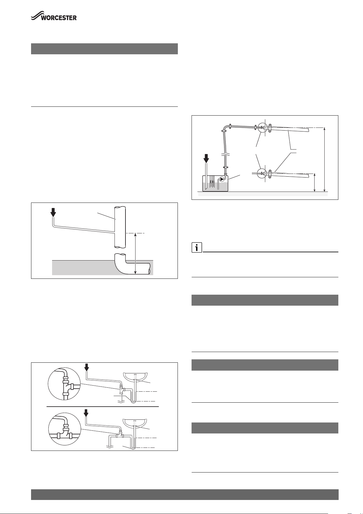
Pre-Installation
Condensate pipe work - Unheated internal areas
NOTICE:
Unheated internal areas.
Although the large volume siphon will reduce the risk of freezing,
condensate discharge may freeze in areas during prolonged cold
temperatures.
▶ Internal pipe runs in unheated areas such as lofts, basements and
garages should be treated as external runs.
For additional information refer to “External Connections” section.
4.5.3 Internal connections
Soil stack connection
Figure 32
In order to minimise risk of freezing during prolonged cold spells, the
following methods of installing condensate drainage pipe should be
adopted.
Wherever possible, the condensate drainage pipe should be routed and
terminated so that the condensate drains away from the appliance under
gravity to a suitable internal foul water discharge point such as an
internal soil and vent stack. A suitable permanent connection to the foul
waste pipe should be used.
1
2
Condensate pump
Figure 34
Where direct connection to a “gravity discharge” pipe work is not
physically possible, or where very long internal runs would be required to
reach a suitable discharge point, condensate should be removed using a
proprietary condensate pump, of a specification recommended by the
condensate pump manufacturer.
• The pump outlet should discharge to a suitable “gravity discharge”
outlet.
– The condensate then flows, by gravity, through the 22mm plastic
pipe to the condensate discharge point.
Max.
8
C
1
7
Fig. 34 Condensate pump example
[1] Condensate discharge from appliance
[7] Condensate pump
[8] Pipe work transition
[C] Gravity discharge pipe work
Min.
0010023656-001
3
0010012746-001
Fig. 32 Disposal to soil vent stack
[1] Condensate discharge from appliance
[2] Soil and vent stack
[3] Minimum 450mm and up to 3 storeys
Waste pipe connection
Figure 33
Alternatively if the first option is not possible an internal kitchen,
bathroom or washing machine waste pipe etc. can be used.
Ensure that the condensate drain pipe is connected “down stream” of
the waste trap.
1
5
6
1
6
Fig. 33 Waste pipe disposal
[1] Condensate discharge from appliance
[5] Visible air break at plug hole
[6] 75mm sink waste trap
75mm
min.
75mm
min.
5
0010012767-001
Proprietary condensate pump
▶ Ensure minimum and maximum pump lifting heights are followed as
per condensate pump manufacturers instructions.
4.5.4 External connections
NOTICE:
Rainwater down pipe or external drain disposal
Untreated condensate must not be allowed to flow into streams or rivers
▶ A rainwater down pipe or an external drain shall only be used for
condensate disposal if the down pipe or external drain is connected
to a combined foul and rainwater drainage system
▶ Refer to BS 6798 for more information on condensate disposal
NOTICE:
Grey water recover system
Contamination of recovered water
▶ Condensate disposal shall not be allowed into a grey water recovery
system that is intended for re-use
External disposal considerations
NOTICE:
Freezing conditions
Frozen condensate will block the condensate drain pipe and stop the
appliance from running
▶ Pipe lengths should be kept to a minimum and the route as vertically
as possible.
Greenstar 8000 Style – 6720883855 (2019/01)
25

Pre-Installation
NOTICE:
Condensate waste disposal
▶ Care should be taken when siting a soak-away to avoid causing
damage to existing services
If no other discharge method is possible then the use of an externally run
condensate drainage pipe terminating at a suitable foul water discharge
point, or purpose-designed soak away, may be considered. If this
method is chosen then the following measures should be adopted:
▶ The external run be kept as short as possible and should not exceed
three metres.
Additional precaution against freezing must be taken if the external
pipe run exceeds 3m.
▶ The pipe should be run internally as far as possible before going
externally and the pipe diameter should be increased to a minimum
diameter of 32mm before it passes through the wall to the exterior.
The pipe should be insulated using suitable waterproof and weather
resistant insulation.
▶ The external pipe should take the shortest and least exposed route to
the discharge point, and should "fall" as steeply as possible away
from the appliance, with no horizontal runs in which condensate
might stand.
▶ The use of fittings, elbows etc. should be kept to a minimum and any
internal burrs on cut pipe work should be removed so that the internal
pipe section is as smooth as possible.
▶ All external pipe drainage will be improved if the end is cut at 45° as
opposed to a straight cut.
▶ In situations where there are likely to be extremes of temperature or
exposure, the use of a proprietary trace-heating system for external
pipe work, incorporating an external frost thermostat, should be
considered. All other guidance above and the instructions for the
trace heating system, should be closely followed.
▶ As well as trace heating, other methods of protecting pipe work that
is run externally should be considered to prevent freezing in
prolonged periods.
– Insulation materials can be used, these should be of class “O”
grade with an outer coating that is weather proof, bird/animal
proof, and have a UV resistant finish. A minimum of 19mm thick
insulation is recommended for 32mm external pipes.
– The use of a drain cover (such as those to prevent blockage by
leaves) may offer further protection from wind chill.
– An air break on the external pipe work can reduce the risk of the
appliance being inoperable due to the blocking and backing up of
condense.
1
10
9
11
8
14
12
13
1
9
20
8
12
10
0010012784-001
Fig. 35 Disposal into rain water down pipe
[1] Condensate discharge from appliance
[8] Pipe work transition
[9] Insulate and increase pipe size
[10] External rain water pipe to foul water
[11] External air break
[12] Air gap
[13] Strap-on fitting
[14] 43mm 90° male/female bend
[20] Rain water hopper
Open drain or gully
Figure 36
Where the pipe terminates over an open drain or gully:
• Refer to following example to dispose of condensate to an open drain
or gully.
• The pipe should terminate below the grating level, but above water
level, in order to minimise “wind chill” at the open end.
• The use of a drain cover (such as those used to prevent blockage by
leaves) may offer further protection from wind chill.
Rain water down pipe with external air break
Figure 35
• Refer to following example to dispose of condensate to a rain water
down pipe.
• An air break or rain water hopper must be utilised, between the
appliance condensate outlet and the drainpipe, outside the property,
to avoid flooding of the appliance should the downpipe become
obstructed.
26
1
8
Fig. 36 Disposal to open drain or gully
[1] Condensate discharge from appliance
[8] Pipe work transition
[9] Insulate and increase pipe size
Greenstar 8000 Style – 6720883855 (2019/01)
9
25mm min.
0010023655-001

Open drain or gully with external air break
Figure 37
Where the pipe terminates over an open drain or gully and there is a risk
of ground flooding, then the additional requirement below is
recommended:
• An air break should be installed in the external pipe work as shown to
avoid an airlock during ground flooding/adverse weather conditions
which could prevent the condensate from discharging.
Pre-Installation
400mm min.
25mm min.
1
500mm min.
9
11
10mm min.
8
1
9
11
8
10mm min.
9
12
25mm min.
Fig. 37 Disposal to open drain or gully with air break
[1] Condensate discharge from appliance
[8] Pipe work transition
[9] Insulate and increase pipe size
[11] External air break
[12] Air gap (minimum 10mm)
Condensate soak away considerations
Before deciding to use a purpose-made soak away the history of the
locality and the ability of the surrounding area to disperse the
condensate should be taken into account, e.g. areas prone to flooding
and ground with a high clay content can result in an increased risk of
freezing causing the condensate pipe to become blocked with ice and
the boiler to shut down,
Although it is possible to increase the size of the soak away and the area
with limestone chippings in clay soil areas, if the clay content is high and
prevents effective dispersal of the condensate then a soak away may not
be a suitable means of condensate disposal and an alternative method
should be used.
0010012786-001
12
9
15
15
16
16
17
19
Fig. 38 Disposal to soak-away
[1] Condensate discharge from appliance
[8] Pipe work transition
[9] Insulate and increase pipe size
[11] External air break
[12] Air gap (minimum 10mm)
[15] 100mm minimum Ø plastic pipe
[16] Drainage holes
[17] Limestone chippings
[18] Bottom of sealed tube
[19] Increase size of soak away size and the area with limestone
chippings if in clay soil area.
Not recommended for high clay soil areas.
18
0010012788-001
4.6 Pressure relief discharge
4.6.1 Pressure relief pipe work
Condensate soak away with external air break
Figure 38
• Refer to following example to dispose of condensate to a soak away.
• The condensate soak away must be sited at least 500mm away from
building footings.
• The condensate drainage pipe may be run above or below the ground
to the soak away. The following example shows drainage pipe run
above ground.
• The soak away must use a minimum of a 100mm Ø plastic tube with
two rows of three 12mm holes on 25mm centres and 50mm from the
bottom of the tube. The holes must face away from the house.
• The tube must be surrounded by at least 100mm of limestone
chippings to a depth of 400mm.
• An air break must be installed in the external pipe work as shown to
avoid an airlock during ground flooding/adverse weather conditions
which could prevent the condensate from discharging.
Minimum hole size for the condensate soak away must be 400mm deep
by Ø 300mm.
Greenstar 8000 Style – 6720883855 (2019/01)
CAUTION:
Scalding risk from hot water or steam!
▶ The pressure relief valve (PRV) is an appliance safety device and may
discharge hot water or steam when activated.
▶ The outlet pipe should be sited in such a way that it does not cause a
hazard or an obstruction when discharging, for example above a
window, entrance door or other public access way.
• The pressure relief discharge pipe [1 or 3] should be run in at least
15mm diameter copper pipe or pipe made of a material that will
withstand PRV discharge temperatures and pressures and which
complies with BS 5254 or BS EN 1451.
• Plastic pipe work must be properly supported with a maximum of
300mm between supports to prevent sagging and run downwards
away from the appliance.
• The pressure relief should discharge away from any electrical or other
hazard, preferably to an external drain or soak-away.
• The pipe [1 or 3] should be finished with a partial bend, near the
outlet to face the external wall (as shown) to help prevent freezing.
27
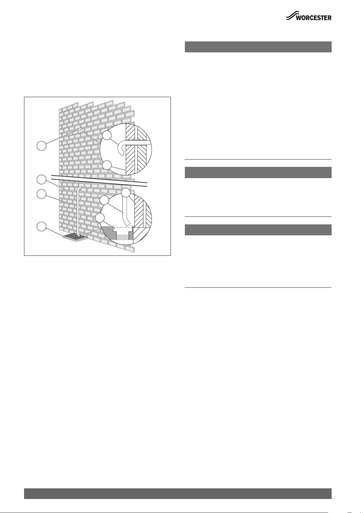
Pre-Installation
• In all normal circumstances a PRV discharge pipe installation as
described above is suffice to meet all but the most exceptional
circumstances.
– Where the PRV discharge pipe could be susceptible to damage,
vandalism, freezing etc that could cause either a blockage or
restriction in the ability to discharge safely then a tundish should
be considered. The tundish should be sited in a position where
damage to the property or occupants cannot occur from any
spillage or discharge.
1
1
2
2
3
2
3
4
4
6720818077-38.1Wo
Fig. 39 Pressure relief pipe work
[1] Discharge pipe (turned back onto external wall example)
[2] Outside wall
[3] Discharge pipe (into drain or gully example)
[4] External drain
4.6.2 Alternative PRV connections - Combined PRV/condensate
The PRV or a combined PRV/ condensate discharge can be connected
into a suitable internal waste system, the installer must ensure that all
the pipe work, including the waste pipe, is capable of withstanding PRV
temperatures and pressures.
Connection to a waste water pipe is possible by using either:
• A shielded tundish with non-return valve can be used to discharge
upstream of a trap (there must not be a trap directly in the PRV
discharge pipe without a tundish.
• A PRV can discharge directly into a suitable waste pipe downstream
of a trap. Connections must be on top of the pipe to ensure they do
not block. A Hotun (or similar) can be fitted for visual indication if
desired but is not necessary.
The guidance of BS 6798 sections 6.3.5 and 6.4.3.2a must be followed.
4.7 Cleaning primary systems
NOTICE:
Risk of damage to system or appliance!
Debris from the system can damage the appliance and reduce efficiency.
Failure to comply with the guidelines for the use of water treatment with
the appliance will invalidate the appliance guarantee and contravene the
Building Regulations.
▶ It is a requirement of the Building Services Compliance Guide which
is a second tier document to the Building Regulations to flush and
inhibit the primary water system in accordance with BS 7593.
▶ The Building Services Compliance Guide recommends that a primary
water cleanser is fitted to the system.
▶ Worcester Bosch recommend fitting a filter that will help remove both
magnetite and non-magnetic debris.
Worcester offers two filters that helps remove both magnetite and
non-magnetic debris; 22mm version, part number 7 733 600 236
and a 28mm version, part number 7 733 600 237.
NOTICE:
Risk of damage to system or appliance!
Artificially softened water must not be used to fill the central heating
system.
▶ Salt based, artificially softened water MUST NOT be used to fill the
system
NOTICE:
Sealing agents
Normally the addition of sealing agents to the system water is not
permitted as this can cause problems with deposits left in the heat
exchanger.
▶ Heating systems may lose small amounts of water over time. In cases
where all attempts to find a system micro leak have failed, Worcester,
Bosch Group supports the use of Fernox F4 leak sealer.
Before cleaning the system:
▶ Ensure that the system and pipe work is in good working order.
▶ Where possible keep the existing appliance/circulating pump in
place when flushing the system before installing the new
appliance. Alternatively use an after market power flushing
system or similar to remove magnetite and other debris from the
central heating system.
– Even new central heating systems contain contaminants that
need to be removed before treating the system with inhibitor/antifreeze.
– When an appliance is installed onto a new system then it is
possible to use the appliance whilst cleaning the system. A system
filter must be fitted to the return to reduce the risk of
contaminants entering the appliance.
▶ Follow the guidance of BS7593.
Inhibitor
Add a suitable inhibitor or combined inhibitor/anti-freeze, if the system
is exposed to freezing conditions, to the heating system in accordance
with the DWTA code of practice and manufacturer‘s guidelines.
Products approved to the BuildCert standard are deemed as compatible
with the components and equipment within the appliance and system.
28
Greenstar 8000 Style – 6720883855 (2019/01)

Installation
WARNING:
Sealing agents
▶ In cases where all attempts to find a micro leak have failed,
Worcester, Bosch Group supports the use of Fernox F4 leak sealer.
Water treatment products
Suitable water treatment products can be obtained from the following
manufacturers:
ADEY 01242 546717
www.adey.com
FERNOX 0870 601 5000
www.fernox.com
SENTINEL 0800 389 4670
www.sentinel-solutions.net
Table 12
4.7.1 Flushing the system
Flushing the system using existing appliance/circulating pump or new
appliance.
▶ Fill the system with cold water and check for leaks.
▶ Open all drain cocks and drain the system.
▶ Close drain cocks and add a suitable flushing agent compatible with
aluminium at the correct strength for the system conditions in
accordance with the manufacturer‘s instructions.
▶ Mark the position of the lockshield valves and open them fully.
▶ Fully open all TRVs.
▶ Circulate the flushing agent before the appliance is fired up.
▶ Run the appliance/system at normal operating temperature as
directed by the manufacturer of the flushing agent.
▶ Drain and thoroughly flush the system to remove the flushing agent
and debris. Do not drain the system through the PRV of new
appliances.
▶ It may be necessary to use a power flushing machine to aid the
cleansing procedure in some circumstances.
▶ Close the drain cocks and manual air vents.
▶ Existing appliance/circulating pump if continuing to use before
new appliance is installed.
– Add a suitable inhibitor to the system in accordance with the
manufacturers instructions.
– Fill the system to between 1 and 1.5 bar via a WRAS approved
filling loop.
– Vent any air from the appliance and system.
▶ New appliance.
– Once the new appliance has been installed follow the guidance in
Filling the appliance and adding inhibitor section.
5 Installation
NOTICE:
Risk of damage to appliance or accessories.
▶ All the previous pre-installation sections must be read and
requirements met before starting the appliance or flue installations.
CAUTION:
Risk of injury through incorrect lifting and carrying!
▶ Only lift a manageable weight, or ask for help.
▶ Bend the knees and keep the back straight with feet apart, when
lifting or putting down heavy objects.
▶ DO NOT lift and twist at the same time.
▶ Lift and carry object close to the body.
Appliance on site
▶ Check contents of delivery are undamaged.
▶ Remove the appliance from its packaging check the contents against
the scope of delivery.
▶ Once the appliance is unpacked the installation can commence.
Important handling instructions
• It is advised that two people are used to carry the carton from the van
to the point of delivery.
• Once the car ton has been delivered, the outer carton is removed first.
Care should be taken when releasing the straps. If a sharp implement
is used make sure the outer carton is not pierced and that the
implement is used in such a way so that it may not cause personal
injury.
• All sharp objects must be covered or the blade retracted after use and
put away in a safe place. Care should be taken when lifting the
appliance from the base and the proper technique for safe lifting of
any heavy object should be strictly observed.
Greenstar 8000 Style – 6720883855 (2019/01)
29

Installation
Unpacking
1
5
1.
2
6a 6
5a
43
1.
2.
2.
7
2.
Fig. 40 Unpacking
Additional requirements for roof space installations
• The unpacked appliance can now be moved into the loft space
• Two sets of steps should be used.
• Two people should share the lifting of the appliance up to the loft
hatch, tilt and slid on its back into the loft space.
• Ensure that the roof space has permanent fixed lighting, a permanent
fixed retractable ladder and a fixed floor area, from the hatch to the
30
0010023424-001
appliance installation point. This will allow access for installation,
normal use and servicing.
Before installing the appliance, ensure that the system has been cleaned
Greenstar 8000 Style – 6720883855 (2019/01)

5.1 Position the appliance
S
S
Installation
WARNING:
▶ Ensure the mains gas supply is isolated before starting any work
and follow all relevant safety precautions.
Appliance positioning
▶ Ensure the appliance is mounted onto a flat, fixed rigid surface
capable of supporting the appliance weight.
▶ Ensure all aspects of the installation are considered when positioning
the appliance, flue run and discharge, condensate disposal, PRV
discharge etc.
WARNING:
Damage to property!
Damage caused by drilling into pipes, electrical cables, damp proof
course or other hazards.
▶ Before drilling ensure that there are no obstructions or other hazards.
NOTICE:
Damage to appliance!
Residue, metal shavings, and contaminants in the system pipe work can
damage the appliance.
▶ Flush the system pipe work thoroughly to remove all residue.
▶ Follow the instructions with respect to cleaning primary systems.
Running pipes behind the appliance.
• Do not cross a pipe over another.
• The area around a rear flue outlet must be avoided.
5.1.1 Mounting frame fixing
Flue turret
▶ The flue turret has an in-built 3° angle giving the flue assembly the rise
from the appliance to ensure the condensate flows back to the
appliance.
Rear flue outlet [2].
▶ Mark centre line of flue to be used; the external diameter of the hole
can also be marked if required.
▶ If extensions are to be added then the complete flue must rise at an
angle of 3° from the appliance.
Side flue outlet [1].
▶ Mark from the centre line of the wall mounting template to the wall
which the flue will pass through.
▶ Allow for a rise of 52mm per metre length of flue, to give a 3° angle.
Example hole size.
• If a 60/100mm diameter flue is to be used, a 125mm diameter hole
is required.
• If using the weather sealing collar by pushing it through from inside
the property, then a 150mm diameter hole is required to
accommodate this.
Flue outlet position marked and ready to drill hole.
▶ Drill hole using a core drill or similar.
▶ Clear any debris from the site.
Appliance fixings and flue outlet drilled and ready.
▶ Remove the wall mounting template.
1
2
3
Existing wall fixings positions (CDi Classic)
ALL MOUNTING
TE
▶The existing wall fixings can be used only if they are still
4
deemed by a competent person able to support the new appliance.
Wall mounting template
▶ The wall mounting template has been sized to allow for the minimum
clearances around the appliance, ( section "Appliance
clearances").
figure 41
The appliance wall mounting template shows the relative positions of the
flue and the top and bottom fixings of the wall mounting frame.
▶ Fix the wall mounting template [3] to the wall in the desired position.
▶ Drill the holes [4] through the template for the primary fixing points
as indicated on the template.
– Additional fixing points for the appliance will be indicated on the
wall mounting template.
Fig. 41 Wall mounting template
1 Side exit flue example
2 Rear exit flue example
3 Wall mounting template
4 Primary fixing points
D 87mm
0010019928-001
Flue outlet position.
The appliance wall mounting template has the flue centre lines for the
following flue systems:
• 60/100mm
• 80/125mm
Carry handles For transportation of the appliance always use the carry handles [1] and
[2] (with the control unit in the closed position).
Greenstar 8000 Style – 6720883855 (2019/01)
31

Installation
1
2
0010023273-001
Fig. 42 Transport, lifting and handling
Preparing the appliance installation
NOTICE:
Incorrect mounting can cause material damage.
If the appliance is mounted incorrectly, it may fall off the wall.
▶ Only install the appliance on a rigid, solid wall. This wall must be able
to carry the weight of the appliance and must at least be as large as
the bearing surface of the appliance.
▶ Only use screws and wall plugs that are suitable for the wall type and
weight of the appliance.
0010023676-001
Fig. 43 Fitting the mounting bracket and the mounting plate
To make it easier to install the pipework, we recommend using a
mounting plate. More information about this accessory can be found in
our main catalogue.
▶ Remove the packaging, observing all notices in the packaging.
▶ Make sure that the gas type specified on the data plate is the same as
the gas type supplied.
▶ Make sure that the installation location is in the country of destination
specified on the data plate.
▶ Affix an installation template (if available) to the wall.
▶ Check whether the screws and wall plugs supplied with the appliance
can be used.
▶ Remove installation template from wall.
▶ Drill suitable holes for the selected wall plugs and screws.
▶ Fasten the mounting bracket to the wall using 4 screws and wall plugs
(scope of delivery).
▶ Attach the mounting plate to the lower screws and tighten.
5.2 Appliance connections
WARNING:
Appliance gas connection
▶ Ensure the mains gas supply is isolated before starting any work
and follow all relevant safety precautions.
NOTICE:
Appliance hydraulic connections
▶ Ensure all water pipe work, to be connected, is isolated/drained and
observe all relevant safety precautions.
▶ Be aware of plastic components when using a naked flame on pipe
work.
Surplus water may be present inside the appliance due to factory testing.
External condensate pipe work or internal pipe runs in unheated areas
such as lofts, basements and garages exposed to prolonged cold
temperatures should be protected chapter 4.5.
32
NOTICE:
Commissioning without water damages the appliance!
▶ Operate this appliance only when filled with water
Greenstar 8000 Style – 6720883855 (2019/01)
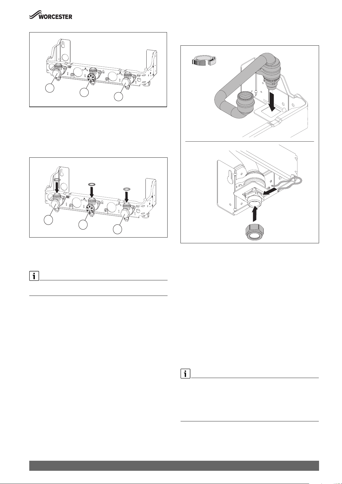
Installation
▶ Apply a smear of silicone lubricant to the seal to ease connection
later.
1
Fig. 44 Connections on the gas and the water side
[1] Heating flow valve
[2] Gas isolator
[3] Heating return valve
Preparing the wallframe
▶ Fit sealing washers to service valves before hanging appliance.
2
3
0010023669-001
1
2
Fig. 45 Fitting the sealing washers
[1] CH flow (22 mm)
[2] Gas inlet (22 mm bonded washer)
[3] CH return (22 mm)
Before hanging the appliance onto the wall mounting frame ensure that
the pressure relief Drain Pipe is connected securely.
3
0010023674-001
4.
1.
3.
2.
0010023277-001
Fig. 46 Connect PRV discharge pipe
5.3 Hanging the appliance
Before hanging the appliance
1. Remove the orange plastic protective cover strip fitted to the
appliance internal pipes by tilting the appliance forward, taking care
to protect the floor from residual water. It is not necessary to lay the
appliance on its back.
2. After soldering/connecting pipes, ensure that the appliance internal
plastic PRV pipe [1] is then connected to the Pre-plumbing manifold
(the printing on the pipe must be facing towards you).
3. Ensure that 3 black plastic ratchet clips are securely fixed and
tightened. Ratchet clip number 4 must be fitted but left loose until the
boiler is hung and connection to the PRV is made ( Fig. 45 and Fig.
48).
4. The appliance is a 2 person lift. Ensure that the control panel is in its
closed position and the top and side panels are removed before lifting
the appliance.
Greenstar 8000 Style – 6720883855 (2019/01)
Before hanging the appliance.
If fitting the optional integral diverter valve kit, the following needs to be
completed ( Optional integral diverter valve instructions for fitting
details):
▶ The internal cylinder service connections need fitting.
▶ The internal cylinder pipe work need fitting.
33

Installation
Hanging the appliance
▶ Ensure that top and side panels are removed.
▶ Fit the sealing washers to service valves.
▶ Hang the appliance on to the wall mounting frame by the centre hook.
▶ Unlock the condensate trap and pull it forwards ( Fig. 90).
▶ Check the positioning of the sealing washers on the pipe
connections.
▶ Tighten the union nuts on the pipe connections starting with the CH
return on the right.
It is recommended the lifting operation is carried out by 2 people,
observing all precautions for safe lifting of heavy objects
Do not lift by the top case panel. There are two handling holes
incorporated into the inner casing left and right in the lower section of
the appliance.
1.
Fitting the condensate pipework
▶ Secure the pipe to the wall at the last joint.
▶ Ensure the pipe protrudes through the wall frame by 25mm.
▶ If exiting through the wall, to run externally, the pipe must have a 3°
fall and be increased to a 32mm insulated pipe.
25mm
6720806944-04.1Wo
Fig. 49 Fitting the condensate pipes to the mounting plate
Condensate connection
Never terminate or discharge into any open source, including; sink,
bath, shower, bidet, toilet etc.
2.
0010023675-001
Fig. 47 Hanging the boiler
5. Make connections between the boiler and the pre-plumbing manifold
and the pre-plumbing manifold and the system pipes.
▶ Connect the gas supply to the boiler gas cock 22mm compression.
▶ Connect cold water in and DHW out to the boiler‘s 15mm
compression connectors.
▶ Connect the CH flow and CH return pipes to the boiler‘s 22mm
compression connections.
▶ Connect the condensate discharge pipe work to the boiler‘s
condensate outlet connections.
Fitting the drain pipe on the heating pressure relief valve
1. 2.
Any external condensate pipe work of an excessive run should be
protected with weather resistant insulation to help prevent freezing.
▶ Ensure that the condensate drain is 22mm diameter plastic pipe. It
must fall at least 52mm per metre towards the outlet.
▶ Refer to Fig. 50, condensate connection:
▶ Align the installation side plastic pipe work through the pre-plumbing
manifold.
▶ Connect the installation side plastic pipe work to the end of the
condensate hose.
▶ Push the plastic pipe work inside the condensate hose at least
25mm.
3.
0010023577-001
Fig. 48 Fitting the pipe on the (heating) pressure relief valve
34
0010023670-001
Fig. 50 Condensate connection
Greenstar 8000 Style – 6720883855 (2019/01)
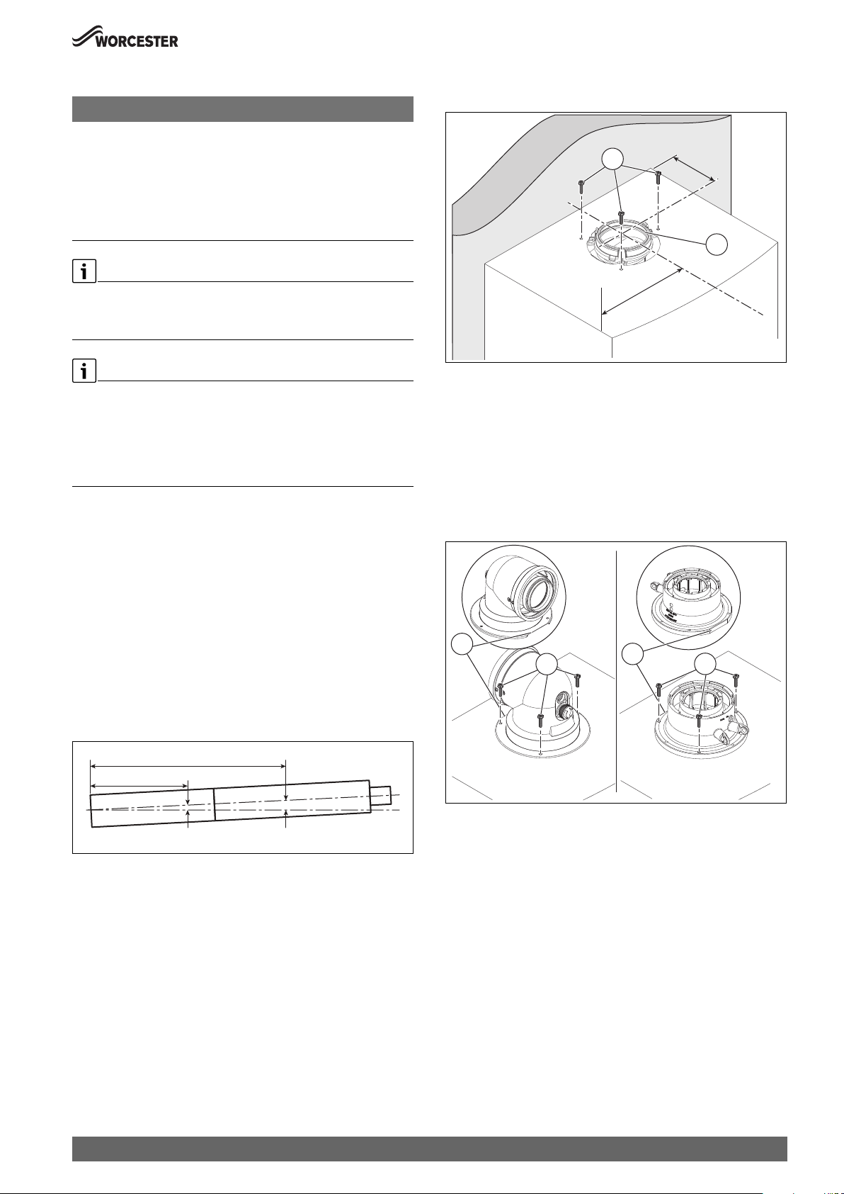
Installation
5.4 Flue turret/adaptor installation
NOTICE:
Flue installation
▶ Refer to the Flue Kit Installation instructions provided with your flue
kit to correctly install the flue with this appliance.
▶ Do not exceed the maximum straight length for a horizontal or vertical
flue or a 60mm plume management system (if used) as stated in the
relevant Installation and Maintenance Instructions manual or
addendum.
Telescopic flue
▶ Cutting the flue to an exact measurement is not required as the
telescopic flue terminal can allow for some adjustment.
Apply silicone lubricant to sealing surfaces, to ease assembly of flue
components.
Refer to the manual supplied with the flue kit for complete installation
instructions.
▶ For plume management effective lengths and the effective flue
lengths, chapter 4.4.
Additional notes and reminders:
• Ensure that all cut lengths are square and free from burrs.
• Ensure that the flue and seals are not damaged.
• The flue is sealed when assembled correctly, the components are
pushed fully home and secured.
• The flue rises from the appliance at an angle of 3° or 52mm per metre
length.
• Support the flue at each flue extension joint and at each change of
direction, use suitable brackets and fittings:
– Flue bracket (silver) 100mm part number: 7 738 112 876.
– Support Bracket Kit (silver) 7 738 112 876.
– Flue bracket 100mm part number: 7 716 191 177.
– Flue brackets 100mm x 6 part number: 7 716 191 178.
– Flue bracket 125mm part number: 7 716 191 179.
▶ Check the appliance flue seal [2] is correctly seated and apply
silicone grease.
D
2
W
al
1
l
W
6720806944-84.1Wo
Fig. 52 Flue turret centre
[D] 87mm
[W] 220mm
▶ Align the flue turret/vertical adaptor to the appliance flue outlet with
flat facing [3] to the rear of the appliance.
The flue turret/adaptor should be pushed straight down, on to the
appliance.
▶ The three inner flue tube retaining screws [1] are, re-used for the flue
turret and replacement retaining screws [4] supplied with the
adaptor kit are used to secure turret/adaptor to the appliance.
3
1
3
4
2,000mm
1,000mm
104mm52mm
Fig. 51 Slope for condensate disposal
▶ Remove the three inner flue tube retaining screws [1].
– The inner tube will be held in place in the appliance.
Greenstar 8000 Style – 6720883855 (2019/01)
6720806944-85.1Wo
Fig. 53 Flue turret/adaptor connection
0010013472-001
35

Installation
3.
3.
5.5 Electrical connection
DANGER:
Risk of electric shock!
▶ Isolate electrical components from the power supply (230 V AC)
(fuse, circuit breaker) and secure against unintentional reconnection before carrying out any work.
Information on safe isolation can be found in the Health and Safety
Executive guidance HSG85.
▶ Check for zero potential before proceeding with work, using test
equipment approved to GS38 to confirm that the electricity supply is
disconnected.
Electrical considerations:
▶ All electrical work must be carried out by a competent and authorised
person.
▶ All work must comply with the current IET Wiring Regulations.
▶ The isolator shall be situated next to the appliance for new systems
and, where practicable, replacement appliances.
▶ The mains electrical supply to the appliance must be through either,
a fused double pole isolator or a fused three pin plug and unswitched
socket.
▶ The isolator must have contact separation of 3mm minimum between
poles. Any system connected to the appliance must not have a
separate electrical supply.
▶ Any additional components that are connected to the appliance that
require 230 Volts must be connected to the same supply as the
appliance.
▶ Type A RCDs must be employed where additional protection is
required.
▶ External fuse 3 Amps.
▶ When stripping the wires, ensure copper strands do not fall into the
control box.
5.5.1 Installer connections
Connect external accessories
▶ Flip down the control appliance ( Fig. 54).
▶ Open the cover.
2.
1.
1.
NOTICE:
Risk of damage from hot appliance components.
Hot appliance components can damage electrical cables.
▶ Ensure all electrical cables are in the correct cable guides and away
from hot appliance components.
Cable routing
▶ Route cables through support guides and retaining clips.
▶ Run power cables separately from signal cables. Interference from
power cables can induce spurious faults on signal cables, ensure that
there is at least 100mm separation from each other.
▶ Ensure the cables are of sufficient length to allow the control box to
be moved to the service position.
If the power cable is of insufficient length, accessing the connection
terminal Fig.
▶ Replace with the following cable types:
– H05V2V2F x 0.75 mm
▶ Connect the cable so that the protective conductor is longer than the
other wires.
2
4.
0010023672-001
Fig. 54 Opening the cover
Access to the electrical connections once the cover is opened.
36
Greenstar 8000 Style – 6720883855 (2019/01)

Installation
1
1
1
1
01LF0
1
3
1
1
1
BUS
1
PE
C0
NPWN
S
N
PE
N
IN
V
O
L
L
N
▶ For splash water protection (IP): cut the strain relief to match the
diameter of the cable.
5-7Ø
Ø 8-9
Ø 10-12
13-14Ø
0010019570-001
Fig. 55 Adapting the strain relief to the cable diameter
▶ Guide the cable through the strain relief.
▶ Connect the cable to the terminal strip for external accessories.
▶ Secure the cable on the strain relief.
Power supply (power cables) terminal strip
Symbol Function
Without function
PC0
N
L
Without function
PW2
N
L
Without function
PW1
N
L
Table 13 Power supply (power cables) terminal strip for external
accessories
Low voltage (signal cables) terminal strip
230
230V
230V
IN
N
LL
TW1
1
230V
OUT
UT
N
PC0
PW2
P
FSFRLR
F
N
N
L
FLRL
LR
L
L
T0
1
2
T1
1
2
T0
TW1
T1
LF0
I3
I1
PW1
W
1
1
1
1
2
2
N
L
LF0
1
2
2
I3
1
2
2
BUS
1
1
1
2
2
2
2
I1
BUS
1
1
2
2
0010023776-001
PE
Fig. 57 Low voltage (signal cables) terminal strip
Low voltage (signal cables) connections
230V
PE
230V
IN
OUT
N
LL
N
230V
230V
IN
OUT
N
LL
N
T0
T
TW1
T1
2
N
1
PC0
LF0
T
1
1
2
2
2
2
PW2
N
L
L
PC0
N
FSFRLR
L
LR
LR
LR
TW
PW2
PW1
1
N
N
L
L
FS
FR
Fig. 56 Power supply (power cables) terminal strip
Power supply (power cables) connections
Symbol Function
Protective earth bar
▶ Connect the protective earth for power supply.
Power supply (power cable)
Pre-wired cable (Live and Neutral)
N
230V mains output to external controls/wiring centre
▶ If required: connect power supply for external
controls.
L
230V
IN
L
230V
OUT
N
Switch live (Live Return) to appliance
• k CH demand input
LR
LR
• j DHW demand input (active when optional
integral diverter valve is fitted)
External frost thermostat
• FS output (frost thermostat supply)
FS
FR
• FR input (frost thermostat return)
Symbol Function
Without function.
T0
1
TW1
1
2
Cylinder temperature sensor
1)
▶ Connect cylinder with cylinder temperature sensor
2
directly.
I3
I1
BUS
I
I
1
1
1
2
2
2
2
-or-
▶ Connect cylinder temperature sensor.
PW1
N
Outdoor weather compensation sensor (used when
T1
L
0010023703-001
1
LF0
1
accessory outdoor sensor is connected)
2
▶ Connect the outside temperature sensor.
Without function.
2
1)
Without function.
I3
1
2
Low voltage external room thermostat contact.
I1
1
▶ Remove link and connect the on/off temperature
2
controller.
External control system with EMS bus control,
BUS
1
1) Only available if optional integral diverter valve kit is fitted.
Worcester intelligent wall mounted controls, Boiler IQ.
2
▶ Connect 2 core cable.
Table 14 Low voltage (signal cables) terminal strip for external
accessories
Greenstar 8000 Style – 6720883855 (2019/01)
37
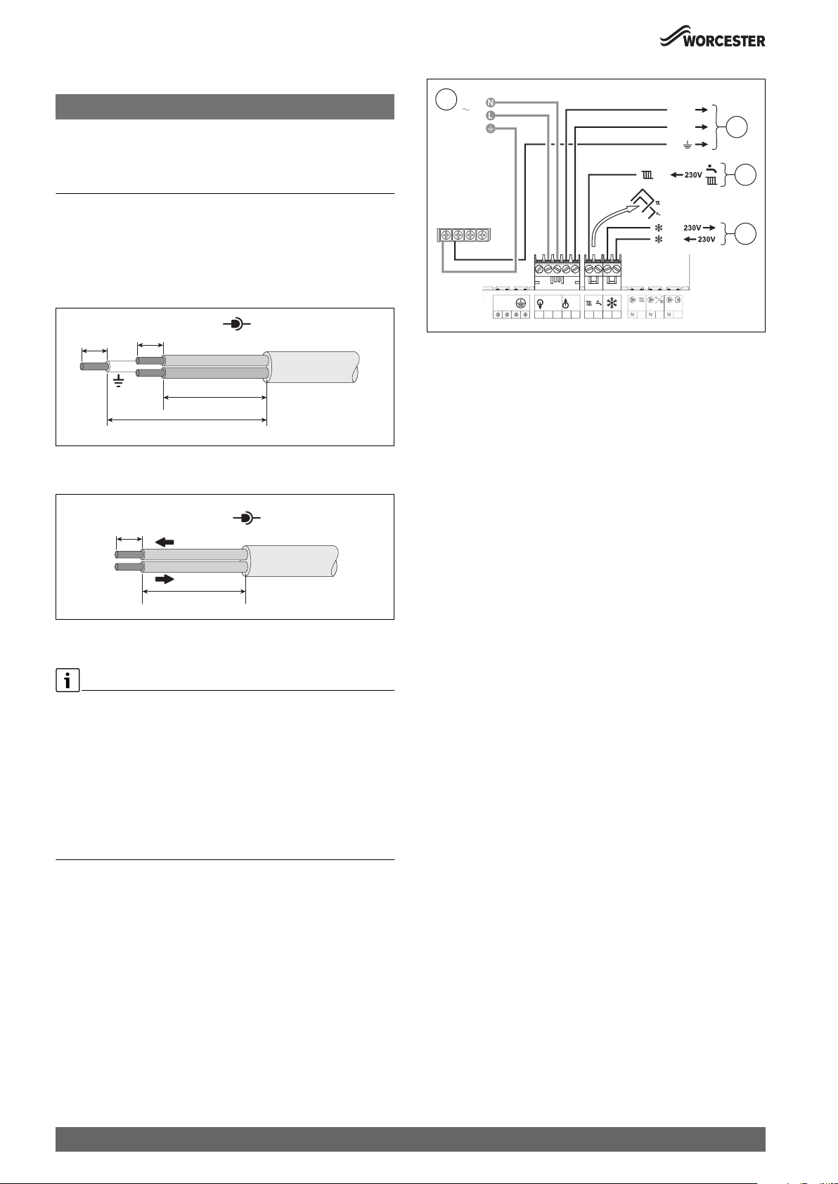
Installation
C0
N
LPW2NL
1NL
5.5.2 Cable preparations
NOTICE:
Damage to control unit!
Small pieces of wire can cause shorts and damage to electronics.
▶ When stripping wires always ensure copper strands do not fall into
the control box.
Mains voltage (power cables), example figure 58
▶ Ensure the conductors (C) can reach the appropriate terminal
connection and that the protective (earth) conductor is longer than
the other wires.
– Power cables connected to the appliance my have different
conductor lengths depending on the termination point.
230V
N
6-8mm
6-8mm
L
C
> C
Fig. 58 Mains voltage (power cables) preparation
Low voltage (signal cables), example figure 59
0010023711-001
1
230V AC
230V
PE
230V
IN
OUT
N
LN
L
P
FSFRLR
LR
LR
FS
FR
PW
L
N
230V OUT
0010022788-001
2
3
4
Fig. 60 External controls connections example
[1] 230V mains supply to the appliance.
[2] 230V supply from the appliance to the wiring centre.
[3] CH & DHW Switch Live (Demand) from the external controls.
[4] External frost protection Live supply and Switch Live (Demand).
6-8mm
0-30V
26-30mm
0010012956-001
Fig. 59 Low voltage (signal cables) preparation
5.5.3 External controls - domestic installations
External equipment or Integral diverter valve kit:
▶ External diverter valve(s) and all other 230V parts are not supplied
with the appliance.
▶ There is an optional integral diverter valve kit, this requires fitting a
diverter valve, internal pipe -work, cylinder sensor & connection.
See optional diverter valve kit instructions for full details. This kit also
allows for the Worcester controls options to be used, which details
can be found in the diver valve kit instructions.
▶ The power supply to external controls must be taken from the
appliance; an alternative power supply must not be used.
Appliance external control connections example
▶ The electrical power supply to the external equipment [2] is supplied
from 230V OUT - L (Live), N (Neutral) and PE - \ (earth) terminals.
▶ The Switch Live from the wiring centre [3]:
– Both pre-wired links are removed, the CH & DHW demands are
combined and wired to the (LR terminal.
– Control for appliance Pre-heat function, optional.
The flow temperature must be set on the central heating control to
a level at least 10 °C above the required cylinder temperature set
on the cylinder control thermostat.
▶ External frost thermostat connections [4]:
– The Live supply is terminal FS
– The Switch Live is terminal FR
38
Greenstar 8000 Style – 6720883855 (2019/01)

6 Commissioning
6.1 Pre-Commissioning checks
DANGER:
Risk of electric shock!
▶ Isolate electrical components from the power supply (230 V AC)
(fuse, circuit breaker) and secure against unintentional reconnection before carrying out any work.
Information on safe isolation can be found in the Health and Safety
Executive guidance HSG85.
▶ Check for zero potential before proceeding with work, using test
equipment approved to GS38 to confirm that the electricity supply is
disconnected.
Checks before commissioning:
▶ Check that the service and water pipes are connected correctly.
▶ Check the gas type specified on the identification plate matches that
of the gas supply.
▶ Check that the appliance is filled with water and under pressure (1.5
bar) and that there are no leaks.
▶ Check that the electrical connections of the appliance are correct:
– Mains electrical supply - 230V, 50Hz
– Compliant earth connection
– Correct polarities.
– External equipment and controls are wired in correctly.
▶ Check that the flue is correctly fitted, airtight, free from any
obstruction and the connections are secure.
▶ Check that the condensate pipe work is connected properly and that
there are no leaks.
NOTICE:
If the appliance is not to be commissioned immediately then, after
successfully completing all of the checks and any rectification work:
▶ Isolate the electricity supply.
▶ Isolate the gas supply.
▶ Close the shut-off valve for the cold water inlet.
▶ Close the water shut-off valves to the appliance.
▶ Label appropriately.
6.2 Water treatment
Primary system flushing (Central Heating)
Ensure that the system has been cleaned:
• Following the guidance of BS 7593:
– Code of Practice for treatment of water in hot water central
heating systems.
• Overview available in Pre-installation, Cleaning primary systems
section.
Inhibitor (Central Heating):
Add a suitable inhibitor that is compatible with aluminium (or combined
inhibitor/anti-freeze, if the system is exposed to freezing conditions), to
the heating system in accordance with the DWTA code of practice and
manufacturer‘s guidelines.
The pH value of the system water must be between 6.5 and 8 or the
appliance warranty will be invalidated.
Commissioning
The inhibitor or combined inhibitor/anti-freeze must not cause damage
to the materials within the appliance (aluminium, mild steel, stainless
steel, copper and brass) and any other materials/components within the
system.
▶ Record the date when the inhibitor was added to the system on the
guarantee card.
▶ The concentration level of inhibitor in the system should be checked
every 12 months or sooner if system content is lost.
NOTICE:
Sealing agents
Normally the addition of sealing agents to the system water is not
permitted as this can cause problems with deposits left in the heat
exchanger.
▶ In cases where all attempts to find a system micro leak have failed,
Worcester, Bosch Group supports the use of Fernox F4 leak sealer.
6.2.1 Filling the appliance and adding Inhibitor
Before pressurising the system.
Additional expansion vessel fitted to the system.
The appliance integral expansion vessel is pre-charged to 1.0bar (equal
to a static head of 10.0m (32.8ft)). A Schrader type valve is fitted to the
expansion vessel to allow for pressure adjustment if required.
▶ If an extra expansion vessel is fitted to the central heating system,
ensure that it is set to the same pressure as the appliance internal
expansion vessel, refer to separate instructions supplied with the
extra expansion vessel.
Filling the system - Open Vent systems
NOTICE:
▶ Salt based softened water must not be used to fill the central heating
system.
▶ Check drain cocks and manual air vents are closed and all radiator
valves are open. Add a suitable inhibitor or combined inhibitor/antifreeze, if the system is exposed to freezing conditions, to the heating
system water in accordance with the manufacturers instructions.
▶ Turn on the water main to the system header and allow the system fill.
▶ The Automatic Air Vent will release any air trapped in the appliance.
▶ Vent all radiators and the primary side of the hot water cylinder,
tighten when completed and check the system for any leaks and
correct if required.
Filling the system - Sealed systems
NOTICE:
▶ Salt based softened water must not be used to fill the central heating
system.
▶ Check drain cocks and manual air vents are closed and all radiator
valves are open. Add a suitable inhibitor or combined inhibitor/anti-
freeze, if the system is exposed to freezing conditions, to the heating
system water in accordance with the manufacturers instructions.
▶ Turn on the water main and open the system valves.
▶ Fill the system to between 1 and 1.5 bar via a WRAS approved filling
loop.
▶ The Automatic Air Vent will release any air trapped in the appliance.
Greenstar 8000 Style – 6720883855 (2019/01)
39

Commissioning
▶ Manually vent all radiators, tighten when completed and check the
system for any leaks and correct if required.
▶ Top up the system pressure if the pressure drops below 1 bar.
▶ Isolate and remove filling loop connections to the system.
6.2.2 Adjusting the operating pressure of the heating system
Display on the pressure gauge
1 bar Minimum charge pressure (when system is cold)
1 - 1.5 bar Optimal charge pressure
3 bar Maximum charge pressure at maximum heating
water temperature must not be exceeded (pressure
relief valve opens).
Table 15
If the indicator is below 1 bar when the system is cold:
▶ Top up the water until the indicator is between 1 bar and 1.5 bar
again.
If pressure is not being maintained:
▶ Check tightness of expansion vessel and heating system.
6.3 Starting the appliance
NOTICE:
Damage to appliance or system!
Running the appliance:
▶ Never run the appliance when the appliance/system is empty or
partially filled.
6.3.1 Control panel overview
8
1
7
2
6
4
Fig. 61 Control panel
[1] Display
[2] and keys: To navigate through menus and increase/decrease
settings
[3] d key: Return/back
[4] OK key: Save settings, Chimney sweeper key: press 5 seconds for
chimney sweeper mode
[5] Menu key
[6] Hot water key: Hot water mode on/off, adjusting the hot water
temperature (only available if the optional integral diverter valve
kit fitted)
[7] Heating key: Heating mode on/off, set the maximum flow
temperature
[8] Burner display: Illuminates when the burner is alight.
35
0010018565-001
See the operating instructions for a description of the user menus.
6.3.2 Turn on the appliance
Set the language the first time the appliance is turned on.
▶ To scroll through the languages, press the or the key.
▶ To select the desired language, press the OK key.
When the display shows Siphon fill. prog., the siphon filling program is
active. The condensate siphon in the appliance is filled (
Chapter 6.3.3).
6.3.3 Siphon filling mode
The siphon filling mode is activated automatically or manually by the
installer on the appliance in the menu settings. The siphon filling mode is
activated in the service menu under > Settings > Special function >
Siphon fill mode.
While the siphon filling mode is active, access to the Hot water menu,
the Heating menu and the service menu is possible.
The siphon filling mode is activated automatically in the following cases:
• The appliance is switched on using the On/Off switch.
• The burner was not in use for at least 28 days.
• After conversion from summer to winter mode.
40
Greenstar 8000 Style – 6720883855 (2019/01)

Commissioning
The next time there is a heat requirement for heating, the appliance is
held at low thermal output for 15 minutes. The siphon filling mode
remains active until the appliance has completed 15 minutes of
operation with increased min. capacity.
During the siphon filling program, Siphon fill. prog. appears on the
display.
The siphon filling mode is interrupted when the chimney sweep mode is
started.
6.4 Chimney sweep mode
You have 30 minutes to take your measurements or to make your
settings. After this time the appliance returns to normal operation.When
running in the chimney sweep mode, the appliance will operate both the
central heating and the domestic hot water circuits. This is to allow
sufficient time for this part of the commissioning procedure. It will be
necessary to run water through the domestic hot water circuit to ensure
that the appliance will not overheat whilst in chimney sweep mode.
In chimney sweep mode the rated output of the appliance can be
selected.
▶ Press the OK key when the countdown is completed and Chimney
sweep is displayed.
▶ Confirm the query with Yes.
▶ Set the desired rated output using the or the keys.
The value is accepted after 2 seconds and marked with a tick.
▶ To exit the chimney sweep mode, press the OK key or the d key.
6.5 Parameters when optional integral diverter valve kit
is fitted
Some menu items/functions will only be available/active if the option
integral diverter valve kit is fitted.
▶ chapter 7
Combustion casing removal
▶ Remove the combustion cover.
Adjustment with casing removed in chimney sweep mode
1. Set the chimney sweep mode and start up the appliance at maximum
rated output.
2. Set the chimney sweep mode and set the appliance at minimum rated
output.
1.
Fig. 62 Removing the combustion cover
2.
0 010 007 441-001
Greenstar 8000 Style – 6720883855 (2019/01)
41

Commissioning
6.6 Checking gas inlet pressure
6.6.1 Checking the gas supply pressure
▶ Switch off the appliance and close the gas isolator.
▶ Unscrew the screw on the test point for the gas supply pressure and
connect a pressure gauge.
▶ Exit the chimney sweep mode.
▶ Switch off the appliance, close the gas isolator, remove the pressure
gauge and tighten the screw.
▶ Check for gas tightness.
1.
T10
0010024761-001
Fig. 63 Gas valve test points (above: SIT valve, below: Honeywell valve)
▶ Open the gas isolator and switch on the appliance.
▶ Ensure that there is heat transfer by opening the radiator valves and
by running a hot tap.
▶ Set the chimney sweep mode and start up the appliance at maximum
rated output.
▶ Check the required gas supply pressure according to table .
Commissioning must not take place outside of the permissible pressure
range.
▶ Identify the cause and rectify the fault.
▶ If this is not possible: isolate the appliance on the gas side and notify
the gas supplier.
2.
3.
0010023566-001
Fig. 64 Refit combustion casing
▶ Refit the combustion casing.
▶ Ensure this cover is engaged onto top bracket [1] before securing
screw [3].
Gas pressure within the system
The appliance must be running at maximum output rate when
performing the gas rate check, ( chapter 6.4).
Refer to the figures below for natural gas or L.P.G gas pressures.
The pressure drop from the meter or at the L.P.G. gas supply to the gas
valve inlet test point must not be more than:
• 2.5 mbar for Natural Gas
• 4 mbar for L.P.G.
Allowed mbar pressure drop
Meter/
LPG supply
Natural gas
19 - 23 1 18 - 22 1.5 16.5 - 20.5
L.P.G.
32 - 45 2.5 29.5 -
mbar range
Table 16
If the pressure drops are greater than shown below, then this would
indicate a problem with the pipe work or connections within the system.
Across
pipe
work
Appliance
inlet
42.5
Across
appliance
1.5 28 - 41
Gas valve
42
Greenstar 8000 Style – 6720883855 (2019/01)

Commissioning
NOTICE:
Do not continue commissioning until the correct gas pressure is
achieved.
Gas supply pressure drop
Meter
Natural Gas
≤ 2.5 mbar
Gas Control
valve
difference
19 - 23 mbar
1 mbar
drop
Appliance inlet
18 - 22 mbar
16.5-20.5 mbar
1.5 mbar
drop
0010023810-001
Fig. 65 Natural Gas pressures
LPG Storage
32 - 45 mbar
L.P.G.
≤ 4.0 mbar
Gas Control
valve
difference
0.5 mbar drop
Regulator
2.0 mbar
drop
Appliance inlet
29.5 - 42.5 mbar
28-41 mbar
1.5 mbar
drop
0010023811-001
Fig. 66 L.P.G. pressures
[≤ ] Less than or equal to
6.7 Checking the gas rate
▶ The gas rate should be measured at the gas meter after the appliance
has been operating for a minimum of 10 minutes at maximum output.
▶ Refer to Technical data section of this manual for the appliance gas
rates and CO/CO
▶ Where a gas meter is not available (e.g. L.P.G.) the CO/CO
ratios.
2
must be
2
checked.
▶ Gas rate must be checked with the appliance in service, maximum
output test mode.
▶ Carry out Gas rating procedures as described in current edition of the
“Essential Gas Safety”.
▶ Ensure all other gas appliances are isolated when carrying out the gas
rate check on the appliance.
▶ Set the chimney sweep mode and start up the appliance at maximum
rated output.
▶ Where a gas meter is not available (e.g. L.P.G.) the CO/CO
must be
2
checked to the units shown in the setting of the air/gas ratio.
▶ If pressure and gas rate are satisfactory press the OK key or the d key
and the boiler will return to normal operation.
▶ Close the gas isolation valve.
▶ Remove the manometer.
▶ Re-seal the screw in the gas inlet pressure test point.
▶ Open the gas isolation valve.
▶ Ensure that there are no gas leaks.
▶ Replace the outer case.
6.8 Checking for gas leaks during operation
▶ Use an approved gas leak detector to check all connections for
possible leaks. The product must be certified as a gas leak testing
agent.
▶ Do not allow the product to come into contact with the electrical
wiring.
6.9 CO and combustion check
The following combustion and flue integrity checks are mandatory and
these values must be recorded on the Benchmark check list, at the end
of these instructions.
Once the gas rate and pressure have been confirmed as acceptable then
the CO and combustion checks can be undertaken.
The flow chart is given for guidance, the details of the checks are given in
the following sections:
• Checking flue integrity, ( chapter 6.10)
• Flue gas analysis, ( chapter 6.11)
Greenstar 8000 Style – 6720883855 (2019/01)
NOTICE:
Before CO and combustion checks:
▶ Verify the appliance is connected to the correct gas type.
▶ Ensure the appliance is supplied with the correct gas inlet pressure
and gas rate as specified previously in the Commissioning section.
▶ Visually check the integrity of the whole flue system and confirm that
all the components are correctly assembled, fixed and supported.
▶ The flue gas analyser must be the correct type as specified in BS
7967. Before use the analyser must have been calibrated as
specified by the manufacturer. The installer must be competent in the
use of the analyser.
▶ Check and zero the analyser in fresh air as specified by the
manufacturer.
▶ The air/gas ratio valve is factory set and must not be adjusted during
commissioning unless this action is recommended following contact
with the Worcester, Bosch Group help line 0330 123 3366.
43

Commissioning
START
HERE
Record values.
Do not adjust
the gas valve.
Set boiler to
maximum rate.
< =
less than
≥ =
greater than
or equal to
No
No
CO < 350ppm
CO/CO2 ratio
< 0.004
Yes
Zero the analyser
in fresh air.
See notice above
O2 ≥ 20.6%
< 0.2%
CO
2
Yes
Check all seals around the
burner, internal flue seals,
Check CO and combustion
Flue integrity test
using analyser
Verify flue integrity
and case seals.
Rectify where necessary.
ratio at minimum rate
O2 ≥ 20.6%
< 0.2%
CO
2
No
No
Yes
Check CO and
combustion ratio
at maximum rate
CO < 350ppm
CO/CO2 ratio
< 0.004
Yes
Set boiler to
minimum rate.
Turn off boiler and
call Worcester, Bosch
Group help line.
No
0330 123 3366
Fig. 67 Commissioning checks flow chart
6.10 Checking flue integrity
Flue integrity check
▶ The combustion casing must be fitted whilst this test is carried out.
▶ Refit the test point plugs after the test has been completed.
The integrity of the flue system and performance of the appliance can be
checked via the flue turret/adaptor sample points.
Air inlet sample point location on flue turret/adaptor.
CO < 350ppm
CO/CO2 ratio
< 0.004
Yes
1
satisfactorily.
No further action
is required.
0010023581-002
2
3
Boiler is operating
0010015568-001
Fig. 68 Flue integrity check test point
[1] Air inlet sample point
[2] Flue turret air inlet blank plug (with retaining ring)
[3] Flue adaptor air inlet blank plug
▶ With the appliance casing on and the appliance running at maximum
output in chimney sweep mode, remove the blanking plug [2 or 3] for
the air inlet sample point [1].
▶ Insert the analyser probe into the air inlet sample point [1].
▶ Allow the readings to stabilise and check that:
–O
is equal to, or greater than 20.6%
2
–CO
is less than 0.2%
2
▶ If the readings are outside these limits then this indicates that there
is a problem with the flue system or combustion circuit.
44
Greenstar 8000 Style – 6720883855 (2019/01)
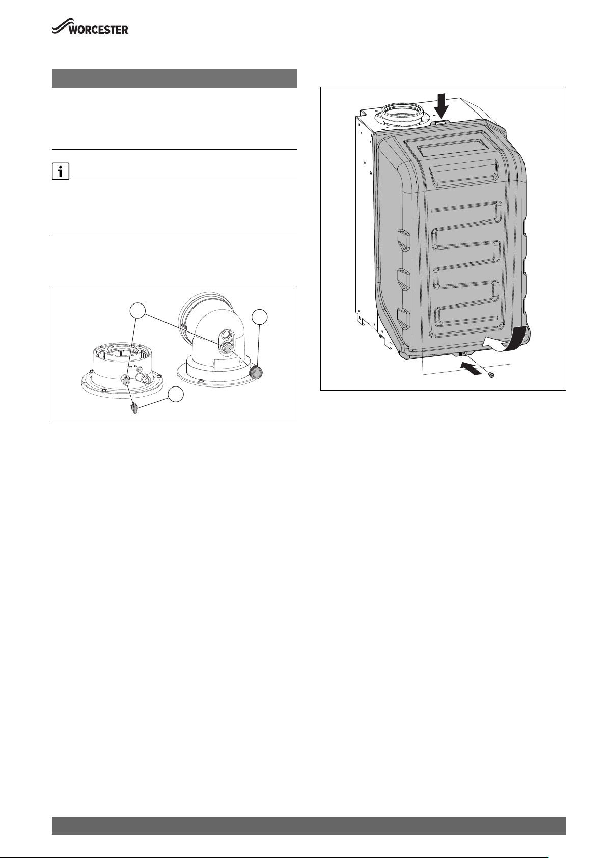
Commissioning
6.11 Flue gas analysis
NOTICE:
Combustion testing
▶ Combustion testing must be carried out by a competent qualified
person. Testing must not be attempted unless the person carrying
out the combustion check is equipped with a calibrated Flue Gas
Analyser conforming to BS 7967 and is competent in its use.
Flue gas analysis
▶ Ensure that the gas inlet pressure has been checked and is
satisfactory.
▶ Refit the test point plugs after the test has been completed.
The flue gas analysis performance of the appliance can be checked via
the flue turret/adaptor sample points.
Flue gas sample point location on flue turret/adaptor.
1
2
6.12 Finishing commissioning
6.12.1 Fitting the combustion casing
1.
2.
3
Fig. 69 Combustion test
[1] Flue gas sample point
[2] Flue turret flue gas blank plug
[3] Flue adaptor flue gas blank plug
6.12.2 Fitting the appliance casing
0010015569-001
3.
0010023566-001
Fig. 70 Fitting the combustion casing
▶ Ensure this cover is engaged onto top bracket [1] before securing
screw [3].
Greenstar 8000 Style – 6720883855 (2019/01)
45
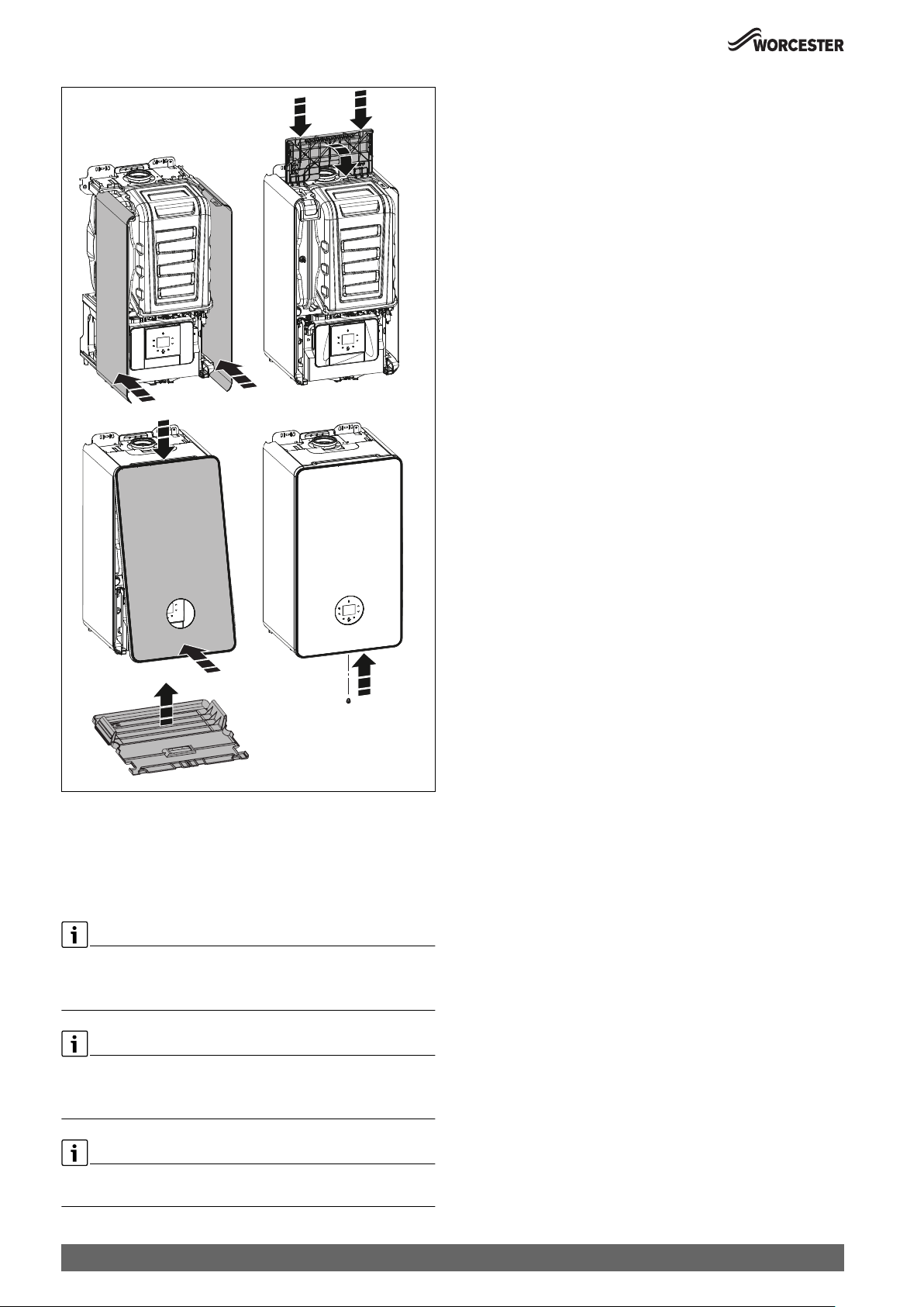
Commissioning
1.
3a. 4.
3b.
Fig. 71 Fitting the appliance casing
[1] side covers
[2] top
[3] front
[4] bottom
2.
0010023240-001
Appliance handover:
▶ Complete the Benchmark Gas Boiler Commissioning Checklist.
▶ Set up the appliance controls and show the customer how to operate
all the control unit/s for central heating operation.
– Also show where in the appliance/controls documentation where
this information can be found.
▶ Where applicable, instruct the customer on:
– the need to occasionally re-pressurise the appliance and the
pressure expected on the pressure menu.
– location of the keyless filling link and system pressure menu.
– the use of the keyless filling link and how to re-pressurise the
system.
– how to set the TRVs.
– how to reset the appliance.
▶ Show the customer where the serial number/appliance information is
located, they will need this information if they call in with a problem
(Benchmark Commissioning checklist on page 75 contains all
relevant appliance information).
▶ Give the customer details of how to contact the installer/ gas
emergency numbers.
▶ Show the customer how to safely isolate the appliance.
▶ Advise the customer where they can find information on the
Worcester, Bosch Group website, www.worcester-bosch.co.uk.
▶ Advise the customer that outside temperatures will affect the output
of the appliance, especially the DHW.
▶ Ensure that all documentation, is left with the appliance or
homeowner.
– Appliance documentation.
– Controls documentation.
– Any other equipment documentation that is connected to the
appliance or system.
▶ Appliance not in use
– If the appliance is not going to be used immediately and may be
exposed to freezing conditions, advise the customer of the
precautions necessary to prevent damage to the appliance,
system and building.
– If the appliance is unused and exposed to freezing conditions,
shut off all the mains supplies and drain the system and
appliance, label accordingly.
▶ Show the customer the location of the condensate pipe run in
unheated or external areas that my be at risk of freezing during
prolonged cold spells.
▶ User recommendation: Arrange an inspection/maintenance
contract with an approved heating contractor.
The front casing is to be secured at the bottom with one screw (as
supplied) against unauthorised removal (electrical safety).
▶ Always secure the casing with this screw.
▶ Remove the protective films from the boiler display and front cover
before handing over to the user.
At the time of commissioning, complete all relevant sections of the
Benchmark Checklist located at the end of this chapter.
46
Greenstar 8000 Style – 6720883855 (2019/01)

6.12.3 Appliance/product guarantee
This appliance/product has a guarantee against faulty materials or
workmanship for a period from the date of installation subject to the
following terms and conditions.
• The guarantee period for your product/component will vary
depending on its type and the accreditation of your installer. To
confirm the guarantee period applicable to your product, speak to
your installer or call 0330 123 2552.
• The guarantee must be registered within 30 days of installation.
• The householder may be asked to prove the date of installation and
that the appliance was correctly commissioned. This should be
documented as a part of the Commissioning Checklist.
• The product must be correctly installed and commissioned in
accordance with the Installation instruction for your product and
meet the requirements of the Benchmark initiative if applicable.
• The product must be maintained, inspected/serviced in accordance
with the manufacturer’s product instructions by a Bosch
Thermotechnology Ltd or other competent Engineer. Proof of
inspection/servicing may be required to validate a guarantee.
• During the period of this guarantee any components of the appliance
that are proven to be faulty or defective in manufacture will be
exchanged or repaired free of charge if repaired directly by Bosch
Thermotechnology Ltd.
• Invoices for attendance and repair of this appliance by third parties
will not be accepted for payment by Bosch Thermotechnology Ltd.
• That any product or part thereof returned for servicing under the
guarantee must be accompanied by a claim stating the Model, Serial
Number, Date of Installation.
• That Bosch Thermotechnology Ltd will not accept responsibility for
damage caused by faulty installation, neglect, misuse or accidental
damage or the nonobservance of the instructions contained in the
Installation and Users Instructions leaflets.
• The appliance has been used only for the normal domestic purposes
for which it was designed.
• That this guarantee applies only to equipment purchased and used in
the United Kingdom of Great Britain and Northern Ireland, the
Republic of Ireland, the Isle of Man or the Channel Islands.
For full terms and conditions, please visit:
www.worcester-bosch.co.uk/guarantee-terms-and-conditions
Guarantee registration
Your appliance/product carries a guarantee against faulty material or
manufacture subject to Terms and Conditions.
To read the full Terms & Conditions please visit us on-line at
www.worcester-bosch.co.uk/guarantee.
Your statutory rights are not affected by the manufacturer’s guarantee
Settings in the service menu
7 Settings in the service menu
Many appliance functions can be set and checked in the service menu. It
includes:
• Info: viewing information
• Settings: general and appliance-specific settings
• Function check: settings for function checks and start of function
checks
• Reset: restoring the factory settings, resetting the maintenance
intervals
• Demo mode: mode for testing and demonstrating the functions.
Power off appliance for exit.
7.1 Operating the service menu
Opening the service menu
▶ Press the Hot water key and the Heating key simultaneously until the
service menu appears.
Closing the service menu
▶ Press the Hot water key or the Heating key.
-or-
▶ Press the d key.
Navigating through the menu
▶ To highlight a menu or a menu item, press the key or the key.
▶ Press the OK key.
The menu or the menu item is displayed.
▶ To return to the next higher menu level, press the d key.
Changing the setting values
▶ Select the menu item with the OK key.
▶ To select the desired value, press the or the key.
▶ Press the OK key.
The new value is saved.
Exiting the menu item without saving values
▶ Press the d key.
The value is not saved.
▶ Enter modified settings.
▶ Affix label to the appliance in a visible location.
Greenstar 8000 Style – 6720883855 (2019/01)
47

Settings in the service menu
7.2 Service menu
7.2.1 Overview of the service menu
Benchmark
– Actual temp.
– DHW flow rate
– Hot water temp.
Info
– Current status
– Current fault
– Fault history
– Boiler
– Mx.heat.outp %
– Mx.heat.outp kW
– Actual temp.
– Set flow temp.
– Low-loss hdr.tmp
– Heating mod.
– Act. burner mod.
– Burner output
– Ionisation current
– Pump mod.
– Outside temp.
– HC1 pump
– Burner starts
– Hours run
– System pressure
–Hot water
– Max. outp.(%)
– Max. outp.(kW)
– Hot water temp.
– DHW act. temp.
– Hot water temp.
– Act.DHWtmp.cyl.
– DHW set temp.
–System
– Contr.device ver.
– Progr. unit ver.
– SW sub-ver.
– Code plug no.
– Code plug ver.
– Time prog. ver.
– Solar
– Collector temp.
– Cyl.temp.bottom
– Collector pump
– Solar fault
Settings
– Hydraulics
– Low-loss header
– DHW configuration
– HC1 configuration
– Pump config.
– Heating
– Mx.heat.outp %
1)
1)
1)
– Standby time
– Clock inh. T. off
– Clock inh. T. on
–Hot water
1)
– Max. DHW output
– DHW circ. pump
– Cycle circ. pump
– Turbine signal del.
– DHW start del.
– Preheat
– Man. TD line
– TD-Temperature
– Max. TD duration
– Start TD
– Stop TD
– Pump
– Pump range map
– Pump ctr. mode
– Min. output
– Max. output
– Pump overrun
– Min.syst.pressure
– Target pressure
– Special function
– Ventilation func.
– Siphon fill. prog.
– 3-WV mid. pos.
– Autom. filling Available for system?
– Autom. filling
– Max. refill time
– Blocking time
– Max. refills
– Reset refilling
– Maintenance
– Maintenance type
– Without
– Boiler run time
– Burner run time
– Service date
– Landlord
2)
1)
– End date
– Maint. reminder
– Installer tel. no.
– Limit values
– Max. flow temp.
– Max. DHW temp.
– Min. boiler outp.
– Heating curve
– Req. odr. temp.
– Htg. curve base
– Htg. curve end
– Summer mode
– Frost prot.
– Frost temp. limit
– Solar
– Max. solar temp.
1) Only available if the optional integral diverter valve kit is fitted. 2) Only available with installed Key (accessories)
48
Greenstar 8000 Style – 6720883855 (2019/01)

– Solar pump type
– Start solar system
Function check
– Activate test
– Burner
– Ignition
–Fan
– Pump
– Cyl. prim. pump
– 3-way valve
– HC1 pump
– DHW circ. pump
– Ionisat.oscill.
– Solar pump
Reset
– Default setting
– Fault history
– Hidden menu: Reset Maintenance Landlord
Demo mode
Settings in the service menu
Greenstar 8000 Style – 6720883855 (2019/01)
49
Settings in the service menu
7.2.2 Benchmark and Info menu
Menu item Comment/restriction
Actual temp. Flow temperature in °C
DHW flow rate Hot water flow rate in l/min
Hot water temp.Outlet temperature in °C
Table 17 Benchmark menu
Menu item Comment/restriction
Current status Tab. 24, page 67
Current fault Tab. 24, page 67
Fault history
Boiler
Mx.heat.outp % Max. heating output in %, Setting value in > Settings > Heating > Mx.heat.outp %
Mx.heat.outp kW Max. heating output in kW
Actual temp. Flow temperature in °C
Set flow temp. Setting value of the flow temperature
Low-loss hdr.tmp Only if installed. Momentary flow temperature in low loss header in °C
Heating mod. Burner modulation (heating) in %
Act. burner mod.
Burner output Current burner output in kW
Ionisation current Current ionisation current in μA
Pump mod. Actual system pump modulation in %
Outside temp. Current outside temperature in °C
HC1 pump Current status on/off
Burner starts Number of burner starts since commissioning
Hours run Elapsed time of the system since commissioning
System pressure Current system pressure in bar
Hot water
Max. outp.(%) Max. hot water output in %
Max. outp.(kW) Max. hot water output in kW
DHW flow rate Current hot water flow rate in l/min
DHW act. temp. Actual hot water temperature in °C
Hot water temp. Current water temperature in °C
Act.DHWtmp.cyl. Current storage temperature in °C
DHW set temp. Setting value of the hot water temperature
Refilling settings
System pressure Current system pressure in bar
System
Contr.device ver. Software version of the control device
Progr. unit ver. Software version of the control unit
Code plug no. Coding plug number
Code plug ver. Coding plug version
Time prog. ver. Version of installed key
Solar
Collector temp. Collector temperature
Cyl.temp.bottom Cylinder temperature at bottom
Collector pump Collector pump
Solar fault Current faults
Table 18 Info menu
50
Greenstar 8000 Style – 6720883855 (2019/01)
Settings in the service menu
7.2.3 Settings menu
The menu is adapted to your system automatically. Some menu items are
only available if the system has been set up accordingly. The menu items
The factory settings are highlighted in the following table.
are only displayed in systems in which the corresponding system
components are installed, e.g. Key Timer.
Menu item Settings/adjustment range Comment/restriction
Hydraulics
Low-loss header • Low loss header not installed in the system
Position of the low loss header temperature sensor
• Low loss header installed, temperature sensor
connected to the wall mounted boiler
• Low loss header installed, temperature sensor
connected to the heating circuit module
• Low loss header installed, but no temperature
sensor is connected
DHW configuration • Not installed
• 3-way valve installed
• System?: Cyl. prim. pump inst. after low loss
hdr.
• System?: Cyl. primary pump installed
HC1 configuration • No heating circuit 1 (HK1) on the appliance
(HK1 not available or not connected via the
heating circuit module)
• No own pump (flow rate for HK1 is realised by
the heating pump)
• Own HC1 pump downstream the low loss
header
• Dedicated pump installed
Pump config. • None
• Heating pump
Heating
Max. heat output Maximum released thermal output [%].
On natural gas applainces:
▶ Measure the gas rate.
▶ Compare the measurement with the setting tables
( Chapter 12.6, page 72).
▶ Correct deviations.
Standby time • 3…10…60 minutes The time interval determines the minimum delay between
starting and restarting the burner.
Clock inh. T. off
Clock inh. T. on
•2 … 6 … 15 Kelvin
• -15... -6...-2 Kelvin
Temperature standby period.
The difference between the current flow temperature and
the set flow temperature until the burner is switched on or
off.
Hot water
Max. DHW output • 10...100 % Maximum power on hot water
DHW circ. pump • Off
Activation of hot water circulation pump
•On
Cycle circ. pump • 1 x 3 minutes/h
• 2 x 3 minutes/h
Number and duration of starts of hot water circulation
pump per hour
• 3 x 3 minutes/h
• 4 x 3 minutes/h
• 5 x 3 minutes/h
• 6 x 3 minutes/h
• Permanent
TD-Temperature • 60...70…80 °C
Max. TD duration • 10…30 minutes Max. duration of legionella protection cycle in minutes
Start TD Start now? Start legionella protection cycle
Stop TD Cancel now? Stop legionella protection cycle
Greenstar 8000 Style – 6720883855 (2019/01)
51

Settings in the service menu
Menu item Settings/adjustment range Comment/restriction
Pump
Pump range map • Output dependent 0: pump rate proportional
to thermal output
▶ Set low pump curve to save energy and avoid possible
flow noise ( Chapter 12.5, page 71).
• Delta-P dependent 1: constant pressure
150 mbar
• Delta-P dependent 2: constant pressure
200 mbar
• Delta-P dependent 3: constant pressure
250 mbar
• Delta-P dependent 4: constant pressure
300 mbar
• Delta-P dependent 5: constant pressure
350 mbar
• Delta-P dependent 6: constant pressure
400 mbar
Pump ctr. mode • Energy saving
• Heat demand
• Saving energy: intelligent heating pump stop in
heating systems with weather-compensated
controller. The heating pump is only switched on
when needed.
• In case of a heat requirement: the flow temperature
controller switches the heating pump. When there is a
heat energy demand, the heating pump starts up with
the burner.
Min. output • 10...100 % Pump rate at minimum thermal output. Only available
with pump characteristic map 0.
Max. output • 10...100 % Pump rate at maximum thermal output. Only available
with pump characteristic map 0.
Pump overrun • 1...2...60 minutes
• 24 h: 24 hours
Run-on time of the heating pump: pump run-on time
begins at the end of the heat requirement.
Min.syst.pressure • 1...2...3 bar
Target pressure • 0.8...1.3...1.8 bar
Special function
Ventilation func. • Off
• Auto
•On
The ventilation function can be activated after
maintenance.
During ventilation, the following appears in the info area
of the standard display Ventilation func.
Siphon fill. prog. • Off (only permissible during maintenance)
• On, boiler min.
• On, heating min.
The trap filling program is activated in the following
cases:
• On, boiler min.: the appliance is switched on using the
On/Off switch.
• On, heating min.: The burner was not in use for at least
28 days.
• The operating mode is switched from summer to
winter mode.
The next time there is a heat requirement for heating, the
appliance is held at low output for 15 minutes. The trap
filling program remains active until the appliance has
completed 15 minutes of operation at low output.
During the trap filling program the following appears in
the info area of the standard display Siphon fill. prog.
3-WV mid. pos. • No
• Yes
The function ensures that the system is fully drained and
that the motor can be easily removed. The 3-way valve
remains at the centre position for approx. 15 minutes.
52
Greenstar 8000 Style – 6720883855 (2019/01)

Settings in the service menu
Menu item Settings/adjustment range Comment/restriction
Maintenance
Maintenance type • Without
• Burner run time
• Boiler run time
• Service date
• Landlord
Landlord:
This menu item allows a date to be set for annual service/
maintenance (End date). The service display appears as a
reminder 30 days before the scheduled date. A contact
telephone number (Installer tel. no.) is shown together
with service display. The tenant should call this number to
arrange a suitable maintenance date. A second reminder
appears at the scheduled date. If the service display is not
reset by the service engineer, the control unit limits the
functions 14 days after the scheduled date.
Reduced functions are set at Maint. reminder:
• DHW reduced: reduced comfort (max. 35 °C flow
temperature)
1)
• Boiler off: central heating and hot water1) functions
are set off.
Limit values
Max. flow temp. • 30...88 °C Limits the adjustment range for the flow temperature.
Max. DHW temp. • 30...80 °C Limits the adjustment range for the hot water
temperature.
Min. boiler outp. • "Minimum rated output"…"maximum rated
output"
Minimum heat output depending on code plug Max output
= 50 %
Heating curve
Req. odr. temp. • Off
•On
When connecting a weather-compensated control unit,
no adjustment to the appliance is required. The system
control unit optimises this setting. This service function
activates a simple, weather-compensated controller with
a linear heating curve. Depending on the on/off input, the
heating is switched on or off.
Htg. curve base • 20…90 °C This is only displayed if the controller was activated. This
can be used to set the base point of the heating curve,
which corresponds to a outside temperature of +20 °C.
Htg. curve end • 20...90 °C This is only displayed if the controller was activated. This
can be used to set the end point of the heating curve,
which corresponds to a outside temperature of -10 °C.
Summer mode • 0...16...30 °C This is only displayed if the controller was activated. This
can be used to set the temperature threshold at which
outside temperature the heating system is to switch to
summer mode.
Frost prot. • Off
•On
Frost temp. limit • 0...5…10 °C Temperature value for the system frost protection.
This service function is only available if the frost
protection function was activated. If the outside
temperature does not exceed the frost threshold
temperature, then the heating pump in the heating circuit
switches on.
1) Only available if optional integral diverter valve kit is fitted.
Table 19 Settings menu
Greenstar 8000 Style – 6720883855 (2019/01)
53

Settings in the service menu
7.2.4 Function check menu
Menu item Settings/adjustment range Comment/restriction
Activate test
Burner • Off...100 % This service function enables testing of the burner.
Ignition • On
• Off
Permanent ignition.
Test the ignition with permanent ignition without gas
supply.
▶ To prevent damages to the ignition transformer, never
leave this function on for longer than 2 minutes.
Fan •On
• Off
Pump • On
Permanent fan operation.
Fan operation without gas supply or ignition.
Permanent pump run (internal or external pumps).
• Off
Cyl. prim. pump •On
• Off
3-way valve • Hot water
Permanent pump run (hot water charge pump); only if
cylinder primary pump is installed.
Permanent position of the 3-way valve.
• Heating
HC1 pump •On
• Off
DHW circ. pump • On
• Off
Ionisat.oscill. •On
Permanent HK1 pump run (downstream the low loss
header).
Permanent hot water circulating pump run; only if hot
water circulation pump is installed.
Check the ionisation measurement function at the flame.
• Off
Solar pump • On
Permanent pump run (solar pump).
• Off
Table 20 Function check menu
7.2.5 Reset menu
Menu item Settings/adjustment range Comment/restriction
Default setting Restore? All settings of the heat source are reset to the respective
default setting. The system needs to be re-commissioned
following this reset.
Fault history Reset? Reset the maintenance first. The fault history of the heat
source is deleted. If currently a fault is present, it is
immediately entered again.
Table 21 Reset menu
7.3 Thermal disinfection
To prevent hot water from becoming contaminated by bacteria such as
legionella, we recommend thermal disinfection after long downtimes.
▶ Open all DHW draw-off points, from the nearest to the one furthest
away, and draw off hot water until hot water at a minimum of 70 °C
has flown from all draw-off points for at least 3 minutes.
▶ Restore the original settings.
CAUTION:
Risk of scalding.
During thermal disinfection, discharging unmixed hot water can cause
serious scalding.
▶ Only use the maximum adjustable hot water temperature for thermal
disinfection.
▶ Inform occupants of the premises of the risk of scalding.
▶ Perform thermal disinfection outside of the normal operating times.
▶ Do not discharge DHW unmixed.
Proper thermal disinfection involves the DHW system including the
draw-off points.
▶ Set the thermal disinfection in the hot water program of the heating
controller ( heating controller operating instructions).
▶ Close DHW draw-off points.
▶ Set any DHW circulation pump to continuous operation.
▶ Wait until the maximum temperature is reached.
54
Greenstar 8000 Style – 6720883855 (2019/01)

Inspection and maintenance
8 Inspection and maintenance
DANGER:
Risk of electric shock!
▶ Isolate electrical components from the power supply (230 V AC)
(fuse, circuit breaker) and secure against unintentional reconnection before carrying out any work.
Information on safe isolation can be found in the Health and Safety
Executive guidance HSG85.
▶ Check for zero potential before proceeding with work, using test
equipment approved to GS38 to confirm that the electricity supply is
disconnected.
CAUTION:
Mains supplies:
▶ Turn off the gas supply and isolate the electrical mains supply before
starting any work on the appliance and observe all relevant safety
precautions.
NOTICE:
Personnel and equipment
▶ Any service work must carried out by competent registered
engineers.
▶ Service work must not be attempted if a calibrated CO/CO
and manometer are not available.
WARNING:
Hot surfaces!
If the appliance has been operating components may be hot.
▶ Ensure precautions are taken when working on the appliance.
CAUTION:
Component replacement:
▶ After replacement of a gas related component, where a gasket or seal
has been disturbed or replaced, check for gas tightness using a gas
sniffer/analyser.
▶ Also after re-assembly, carry out the following checks:
Fan pressure.
Flue gas analysis.
analyser
2
8.1 Inspection and maintenance considerations
• To ensure continued efficient operation the appliance must be
checked at regular interval.
• The frequency of servicing will depend upon the particular
installation conditions and usage, however, normally an annual
service is recommended.
• The extent of the service work required by the appliance is
determined by the operating condition of the appliance when tested
by qualified engineers.
• After each service, the ser vice interval record sheet at the rear of this
manual, must be completed.
See the following instructions for detail of some of the service
requirements:
▶ Check that the safety and regulation appliances (3 bar pressure
release valve, air bleed, etc.) are operating properly.
▶ Check all joints and connections in the system and remake any that
show signs of leakage. Refill and re-pressurise if applicable as
described in the commissioning section.
▶ When it is frequently necessary to add water to maintain pressure in
the installation, even though no leaks have been discovered, perform
an expansion vessel check.
▶ Check that the condensate system is not obstructed, clean and refill
the condensate siphon.
▶ If the appliance is in a compartment or cupboard check that the
specified clearances around the appliance is clear.
▶ Check that the flue system is unobstructed and undamaged, clean/
replace as necessary.
– If fitted ensure the flue terminal guard is also unobstructed and
undamaged.
▶ Operate the appliance and take note of any irregularities.
– Refer to the fault finding pages for rectification procedure.
8.2 Resources for inspection and maintenance
• The following measuring devices are required:
– Electronic flue gas analyser for CO
temperature
– Pressure gauge 0 - 30 mbar (minimum resolution 0.1 mbar)
▶ Use heat conducting paste 8 719 918 658 0.
▶ Use approved greases.
, O2, CO and flue gas
2
8.3 Inspection and maintenance steps
chapter 12.9 “Inspection and maintenance checklist”.
Maximum system pressure
▶ 2.5 bar must not be exceeded when the heating system water is at
maximum temperature. If this pressure is exceeded then an
additional expansion vessel must be fitted into the system return as
close as possible to the appliance.
▶ If the system does not retain the pressure, the pressure relief valve
(PRV) and the heating system should be checked for leaks.
Greenstar 8000 Style – 6720883855 (2019/01)
55

Inspection and maintenance
8.4 Component access
Removing bottom panel
1. Push in the clip securing the bottom panel.
2. Pull bottom panel sidewards to release from service position and
remove.
2.
2.
1.
0010023671-001
Fig. 72 Removing bottom panel
Removing front cover
1. Remove screw from bottom of front panel
2. Push in the green clips securing both sides the outer case.
3. Pull bottom of front cover forwards and upwards to release the clip on
top of the boiler and remove outer case.
1. 1.
0010019013-001
Fig. 73 Removing outer case
8.5 Fan pressure test
NOTICE:
Fan pressure test
▶ The appliance must be running at maximum output in test mode for
the fan pressure test, ( chapter 6.4).
0 010 007 177-001
Fig. 74 Fan pressure test point
56
This test is to determine if the heat exchanger requires cleaning or
attention.
Fan pressure test reading.
▶ The pressure reading will be in negative values.
Greenstar 8000 Style – 6720883855 (2019/01)
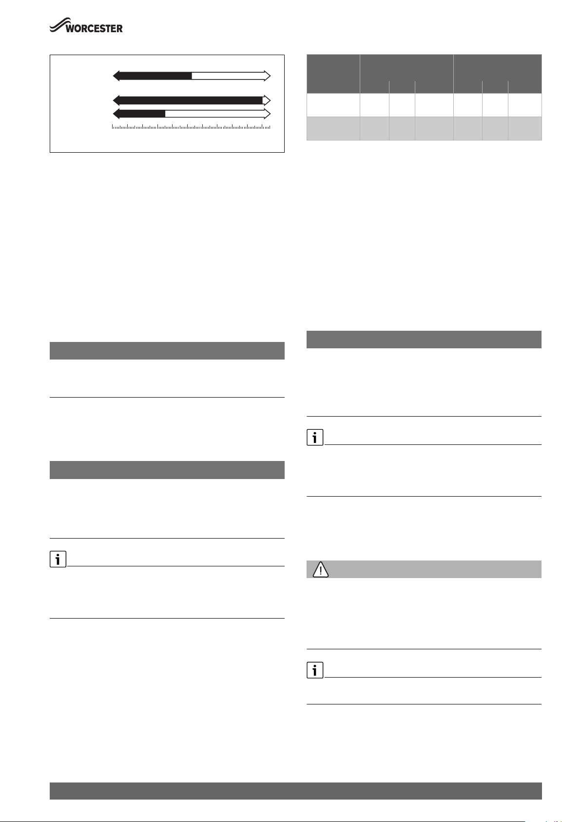
Inspection and maintenance
FAN PRESSURE TEST
Clean the Heat Ex. Heat Ex. ok
Appliances
GR8700iW 30:
GR8700iW 35:
- 3.5
-4
- 4.8
-5
mbar
-6
0
-3
-2-1
-7
- 10.0
-8
-9
0010025222-001
-10
Fig. 75 Fan pressure test values
If the manometer reading is within tolerance, between the appliance
output value [P] mbar and -9.0 mbar.
▶ The heat exchanger/exhaust path/siphon does not require attention.
If the manometer reading is out of tolerance, between 0 mbar and the
appliance output value [P] mbar then carry out the following checks.
▶ Check that the siphon is not restricted or blocked.
▶ Check the exhaust paths for restrictions.
▶ Clean the heat exchanger with a suitable cleaning tool, refer to
cleaning section.
▶ Re-check the fan pressure readings.
If the boiler, after completing the above checks, fails the fan pressure
test then contact Worcester, Bosch Group for advice.
▶ Replace test point cover after completing pressure check.
8.6 Check working gas inlet pressure
NOTICE:
Gas inlet pressure
▶ Do not continue with the other checks if the correct gas inlet pressure
can not be achieved.
▶ Check the gas supply working pressures in the system conform to the
readings shown in the table shown in section 6.6 "Checking gas inlet
pressure".
Maximum rated output Minimum rated output
Gas type CO2O
Natural gas 9.5 %
± 0.4
Liquid
propane (LPG)
Table 22 CO
If the CO
10.8 %
± 0.4
and O2 contents
2
is out of tolerance then please check:
2
CO CO2O
2
4.0 % <250ppm 8.6 %
± 0.4
4.6 % <250ppm 10.2 %
± 0.4
CO
2
5.5 % <75ppm
5.5 % <75ppm
▶ The gas inlet pressure.
▶ The gas rate.
▶ The fan test pressure.
▶ The flue and air intake, plus any possible blockages in the condensate
disposal.
▶ The condition of burner.
▶ For leaks or obstructions in the exhaust paths.
▶CO
is correctly adjusted.
2
The gas valve and venturi are factory set and should not need to be
adjusted, if found to be out of tolerance and when all other possible
causes have been checked, please contact the Worcester Bosch Group
Helpline 0330 123 3366.
8.8 Checking the flue integrity
NOTICE:
▶ Check flue joints are secure, the terminal and the terminal guard, if
fitted are clear and undamaged.
▶ Combustion testing must be carried out by a competent person.
Testing must not be attempted unless the person carrying out the
combustion check is equipped with a calibrated Flue Gas Analyser
conforming to BS 7967 and is competent in its use.
8.7 Flue gas analysis
NOTICE:
Combustion testing
▶ Combustion testing must be carried out by a competent person.
Testing must not be attempted unless the person carrying out the
combustion check is equipped with a calibrated flue gas analyser
conforming to BS 7967 and is competent in its use.
Flue gas analysis
▶ Ensure that the gas inlet pressure has been checked and is
satisfactory.
▶ Refit the test point plugs after the test has been completed.
▶ Set the appliance to maximum and minimum output in chimney
sweep mode for the flue gas analysis checks ( chapter 6.4).
▶ Check that the readings conform to those given in the following
tables. In addition to CO and CO/CO
maximum and minimum CO
2
ratio checks also check the
2
percentage reading.
Flue gas analysis
▶ Ensure that the gas inlet pressure has been checked and is
satisfactory.
▶ Refit the test point plugs after the test has been completed.
▶ Refer to section 6.10 "Checking flue integrity" and check that the
readings conform to those given, confirming flue system and
combustion circuit are ok.
8.9 Cleaning the siphon and heat exchanger
WARNING:
Gaskets and seals - gas related components
▶ Replace gaskets and seals when disturbing gas related components
(e.g. burner, electrode assembly etc.), after cleaning the heat
exchanger.
▶ Do not attempt the cleaning procedure unless new gaskets and seals
are available.
There is an optional tool available to assist in cleaning the heat
exchanger, part number 7 719 001 996.
Greenstar 8000 Style – 6720883855 (2019/01)
57

Inspection and maintenance
8.9.1 Checking the burner
1. Remove the combustion cover Fig. 62.
2. Unscrew the screws on the burner cover.
3. Remove the burner cover.
1.
Fig. 76 Removing the burner cover
▶ Remove the burner and clean its components.
1.
0010023602-001
8.9.2 Checking the non-return valve in the air-gas manifold
1. Unscrew the screws at the air-gas manifold.
2. Remove the air-gas manifold.
1.
2.
1.
2.
0010017096-001
Fig. 78 Removing the air-gas manifold
1. Remove the non-return valve.
2. Check the non-return valve for contamination and cracks.
0010023603-001
Fig. 77 Burner
▶ Reinstall the burner in reverse order, including a new gasket.
▶ Install the burner and the burner cover.
▶ Check the gas/air ratio.
2.
1.
0010007068-001
Fig. 79 Non-return valve in the air-gas manifold
▶ Install the non-return valve.
▶ Install the air-gas manifold.
58
Greenstar 8000 Style – 6720883855 (2019/01)

Inspection and maintenance
8.9.3 Fan removal
1. Undo connection of venturi.
2. Remove venturi and move pipe to the far right.
1.
8.9.4 Cleaning the heat exchanger
Access to the heat exchanger
The following items will have to be removed to gain access to the heat
exchanger for cleaning:
▶ Remove the combustion casing.
▶ Lower the control panel into the service position.
▶ Disconnect electrical wires to the fan, ignition transformer, spark
electrodes, flue overheat thermostat, main heat exchanger
temperature sensor and flow pipe temperature sensor.
▶ Flueway
▶ Fan assembly
▶ Ignition transformer
▶ Spark electrode assembly
▶ Burner housing, burner and gasket
Cleaning the heat exchanger
▶ Remove the siphon and place a suitable container under the outlet to
catch the water and debris.
▶ Protect the controller from water ingress.
The heat exchanger does not have to be removed in order to clean.
The heat exchanger is shown removed from the appliance to illustrate
cleaning more clearly.
2.
Fig. 80 Venturi removal
3. Remove expansion foam (pull towards you).
4. Undo fan connection and remove screw and seal.
5. Remove fan.
4.
3.
5.
▶ Remove the cleaning access cover [1] and seal [2].
1
0010023759-001
2
0010023710-001
Fig. 82 Access cover removal
Fig. 81 Fan removal
Greenstar 8000 Style – 6720883855 (2019/01)
0010023760-001
59
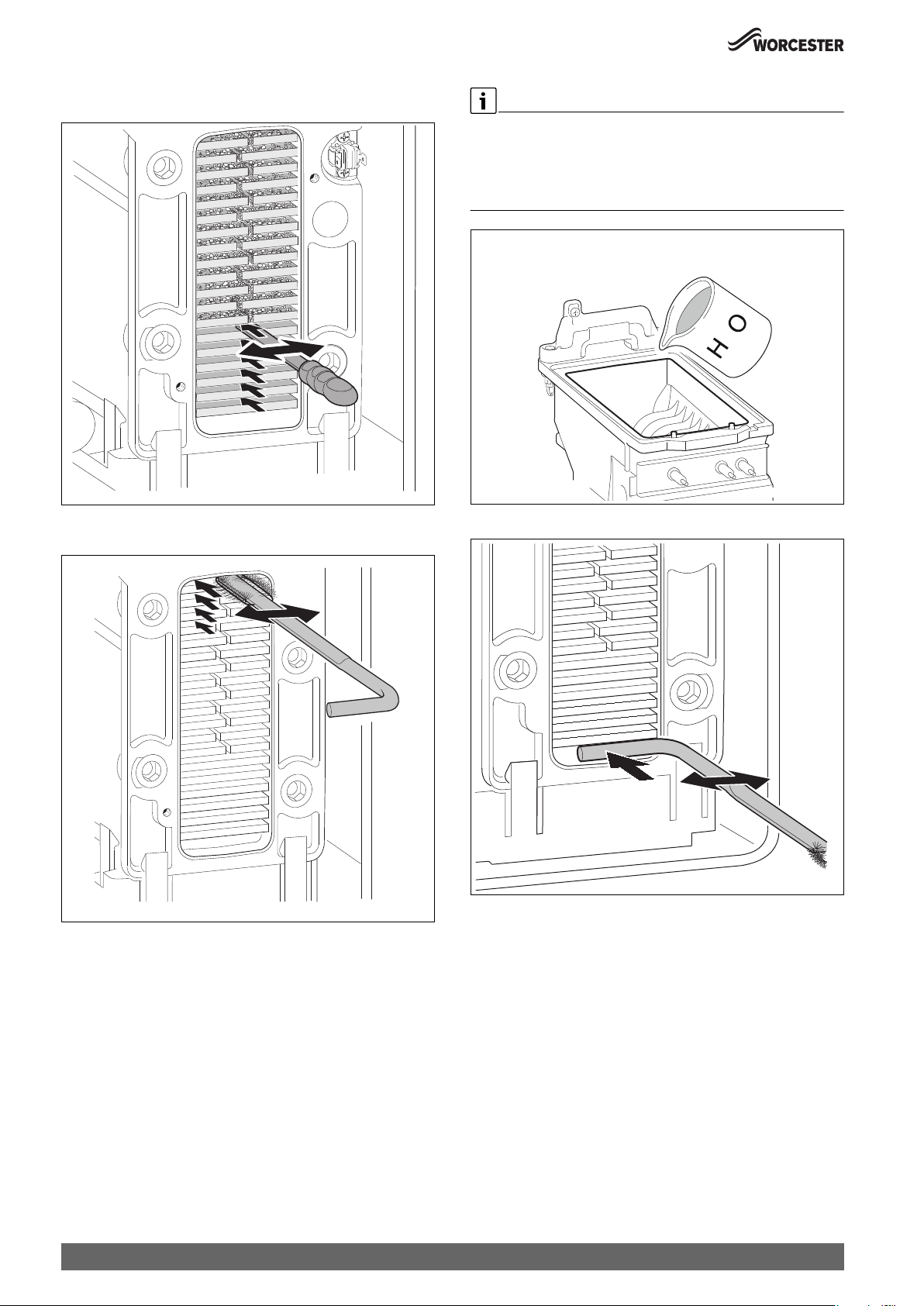
Inspection and maintenance
▶ Using the cleaning blade, working from the bottom to the top, to
loosen any deposits in the heat exchanger.
It is possible to rinse any remaining debris from the heat exchanger
either through the access point or alternatively through the top of the
heat exchanger when the burner is removed.
▶ Pour water into the heat exchanger to rinse the debris through to the
suitable container below the outlet to the siphon.
2
0010023693-001
Fig. 83 Cleaning blade
▶ Using the brush, clean the heat exchanger from top to bottom.
0 010 007 128-001
Fig. 84 Cleaning brush
▶ Use the handle of the brush to remove debris from the condensate
tray.
0010023695-001
Fig. 85 Pour water into the heat exchanger
0 010 007 129-001
Fig. 86 Cleaning debris
60
Greenstar 8000 Style – 6720883855 (2019/01)
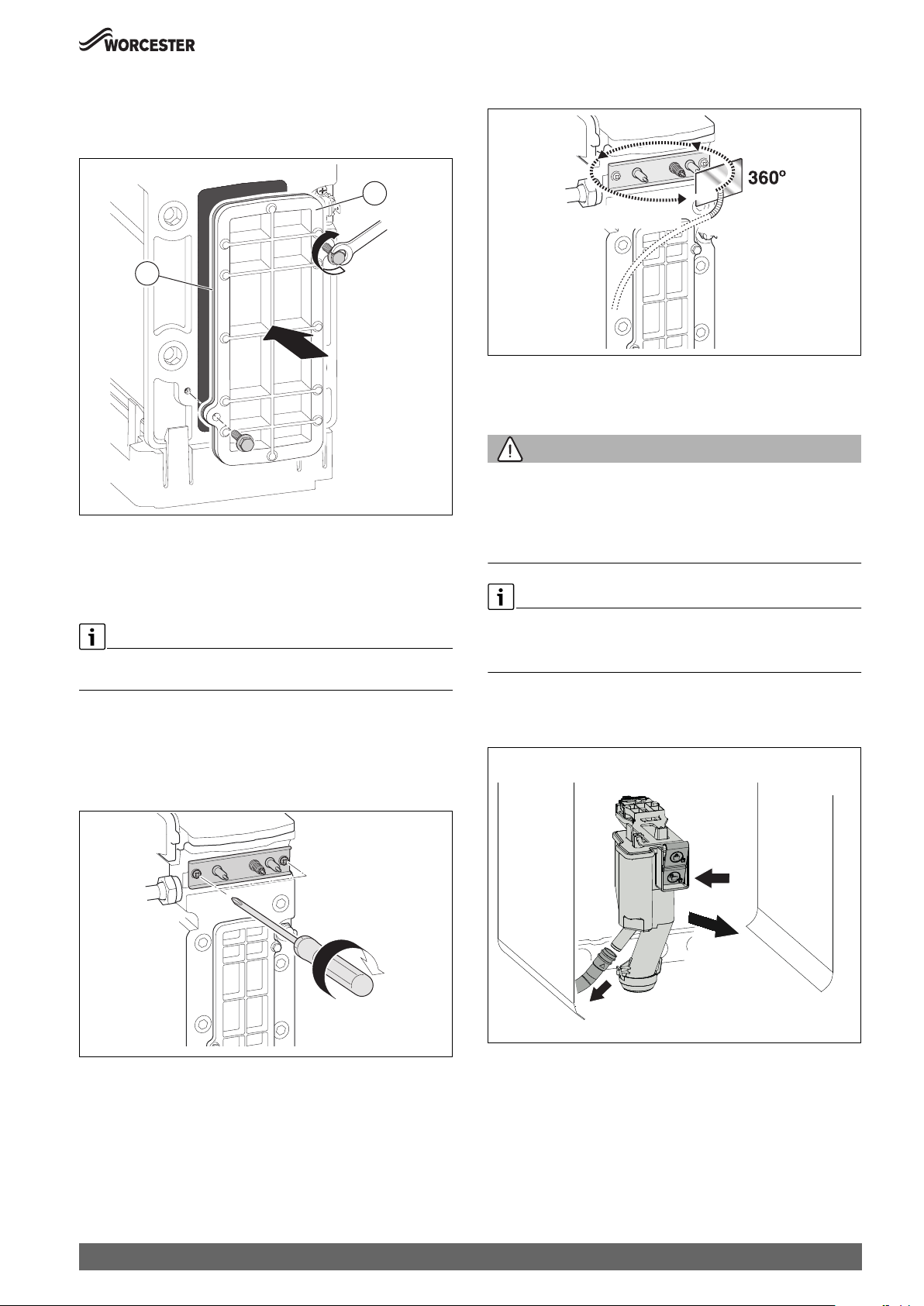
Inspection and maintenance
▶ Refit the cleaning access cover assembly in reverse order the new
seal [2], and the access cover [1].
▶ Hand tighten the bolts and then use a spanner to tighten the bolts a
further half turn.
1
2
0010023584-001
Fig. 87 Re-fitting the access cover
▶ Ensure that the convex side of the burner faces down into the heat
exchanger when re-fitting the burner.
▶ Ensure seal is replaced with new seal and is correctly fitted.
▶ Check the siphon unit is clean before refitting to appliance.
On completion of the heat exchanger cleaning and reassembly, perform
the fan pressure test.
8.9.5 Checking electrodes
▶ Remove the electrode set with gasket.
▶ Check electrodes for contamination.
▶ Clean or replace electrodes if required.
▶ Install electrode set with new gaskets.
▶ Check tightness of electrode set.
Gas/Gaz?
0010 007 499-002
Fig. 89 Checking for leaks
8.9.6 Cleaning the siphon
Cleaning the condensate trap
WARNING:
Danger to life due to poisoning!
If the condensate trap is not filled, poisonous flue gas can escape.
▶ Only turn off the siphon filling program during maintenance, and turn
it back on at the end of maintenance.
▶ Make sure that the condensate drains off properly.
Damages resulting from an insufficiently cleaned condensate trap are
excluded from the warranty.
▶ Clean the condensate trap regularly.
1. Unlock the condensate trap.
2. Pull the condensate trap forwards and tilt to the left for draining.
3. Once empty pull the hose from the condensate trap.
Fig. 88 Installing electrode set
Greenstar 8000 Style – 6720883855 (2019/01)
1.
3 - 4 Nm
2.
3.
0010017101-001
0010023585-001
Fig. 90 Removing the condensate trap
▶ Removing the condensate trap
▶ Clean the condensate trap, and check that the aperture towards the
heat exchanger is clear.
▶ Remove the gasket on the top of the condensate trap.
▶ Check the gasket for cracks, deformation or breakage and replace if
required.
61

Inspection and maintenance
▶ Align the new gasket correctly with the condensate trap.
0010019151-001
Fig. 91 Aligning the new gasket with the condensate trap
▶ Press on the gasket in the required order.
When the gasket is correctly inserted, the pin is visible in the recess
and is flush with the top edge of the gasket.
▶ Check the condensate hose and clean if required.
▶ Fill the condensate trap with approx. 250 ml water.
▶ Replace the condensate trap and check for tightness.
0
3.
1.
2.
0010020541-001
Fig. 93
8.10 Setting the air/gas ratio
NOTICE:
Setting the air/gas ratio
▶ The gas valve and venturi are factory set and should not need to be
adjusted if found to be out of tolerance and when all other possible
causes have been checked, please contact the Worcester Bosch
Group Helpline 0330 123 3366.
Fig. 92 Pressing on the gasket
2.
1.
3.
2.
0010019159-001
NOTICE:
Combustion testing
▶ The setting of the air/gas ratio must be carried out by a competent
registered gas engineer, such as a Gas Safe registered engineer or
British Gas engineer.
▶ Setting of the air/gas ratio must not be attempted unless the person
carrying out the test is equipped with a flue gas analyser conforming
to BS7927 and is competent in its use.
All CO/CO2 readings must be taken with the combustion chamber cover
ON.
Adjustments can only be made with the cover off.
CO2 should be measured 10 minutes after firing the appliance.
62
Greenstar 8000 Style – 6720883855 (2019/01)

Inspection and maintenance
8.10.1 Checking and, if required, adjusting the gas/air ratio
▶ Switch off the appliance.
▶ Remove the front cover.
▶ Remove the combustion cover.
2.
▶ Switch on the appliance.
▶ Remove the plug from the flue gas test port.
▶ Push the flue gas probe centrally into the flue gas test port.
▶ Seal the test point.
0010023633-001
Fig. 96 Flue gas test port
▶ To ensure heat transfer: open the radiator valves.
▶ Set the chimney sweep mode and start up the appliance at maximum
rated output.
▶ Measure the CO
▶ Check the CO
or O2 content.
2
or O2 content at maximum rated output according to
2
Tab. 23 and adjust if required.
1.
Fig. 94 Removing the combustion cover
1
Fig. 95 Setting the adjustable venturi
[1] Security Seal
[2] Adjustable venturi
0 010 007 441-001
2
0 010 020 540-002
Security Seal [1] ( Fig. 95) must be removed before adjusting the Max
CO
setting. Once adjustment has been made the seal must be replaced
2
with part number 8737708988.
▶ To increase the CO2 content, remove seal [1] and turn the adjustable
venturi to the left.
▶ To reduce the CO
content, remove seal [1] and turn the adjustable
2
venturi to the right.
Maximum rated output Minimum rated output
Gas type CO2O
Natural gas 9.5 %
± 0.4
Liquid
propane (LPG)
Table 23 CO
10.8 %
± 0.4
and O2 contents
2
CO CO2O
2
4.0 % <250ppm 8.6 %
± 0.4
4.6 % <250ppm 10.2 %
± 0.4
CO
2
5.5 % <75ppm
5.5 % <75ppm
Greenstar 8000 Style – 6720883855 (2019/01)
63

Replacement parts
▶ Measure the CO content.
The CO content must be < 250 ppm.
▶ Set the minimum rated output.
▶ Measure the CO
or O2 content.
2
▶ Remove the seal from the adjusting screw of the air/gas ratio control
valve (only air/gas ratio control valve is shown in the below Fig. 97)
and set the CO
or O2 content for minimum rated output.
2
4 mm
9 Replacement parts
WARNING:
Mains supplies - Isolate the appliance
▶ Turn off the gas supply and isolate the mains electrical supply before
starting any work and observe all relevant safety precautions.
▶ Drain the appliance/system where necessary and protect any
electrical equipment from water ingress during component
replacement.
WARNING:
Component replacement:
▶ Replace the burner housing gasket and the Flueway sump seal when
re-assembling the heat exchanger. Do not reassembly the heat
exchanger and Flueway until new gaskets and seals are available.
▶ After replacement of a gas related component, where a gasket or seal
has been disturbed or replaced, check for gas tightness using a gas
sniffer/analyser.
▶ On re-assembly check all affected seals for cracks, hardness and
deterioration.
If damaged or in any doubt the seal must be replaced.
▶ Also after re-assembly, carry out the following checks:
Fan pressure.
Flue gas analysis.
T40
0010024762-001
0010024762-001
Fig. 97 Setting the CO
Honeywell valve)
▶ Re-check settings at maximum and minimum rated output and re-
adjust if required.
▶ Seal the air/gas ratio control valve.
▶ Seal the adjustable venturi.
▶ Exit the chimney sweep mode.
▶ Enter the CO
page 75).
▶ Remove the flue gas probe from the flue gas test port and refit the
plug.
or O2 content (above: SIT valve, below:
2
contents in the servicing record (Chapter 12.8,
2
Only use Worcester, Bosch Group original spare parts with this
appliance. Non Worcester, Bosch Group original spare parts will
invalidate the guarantee (if applicable) and any warranty.
▶ A comprehensive list of appliance spares can be found on the website
www.worcester-bosch.co.uk/spares
9.1 Draining the appliance
NOTICE:
Risk of water damage to appliance or property!
Damage from disconnecting water pathways which may have retained
some water.
▶ Take care after draining the appliance to protect equipment/property
from residual water content within components.
Many of the tasks in this section require that the appliance be isolated
and drained. This will be indicated in the manual if required.
▶ The boiler drain is already connected to the condensate trap for ease
of draining.
-or-
▶ Connect a suitable hose firmly to the drain point and run the hose
outside to a suitable point or container.
▶ Turn the drain valve a ¼ turn anti-clockwise to open the drain. Turn
the valve firmly clockwise to close.
64
Greenstar 8000 Style – 6720883855 (2019/01)
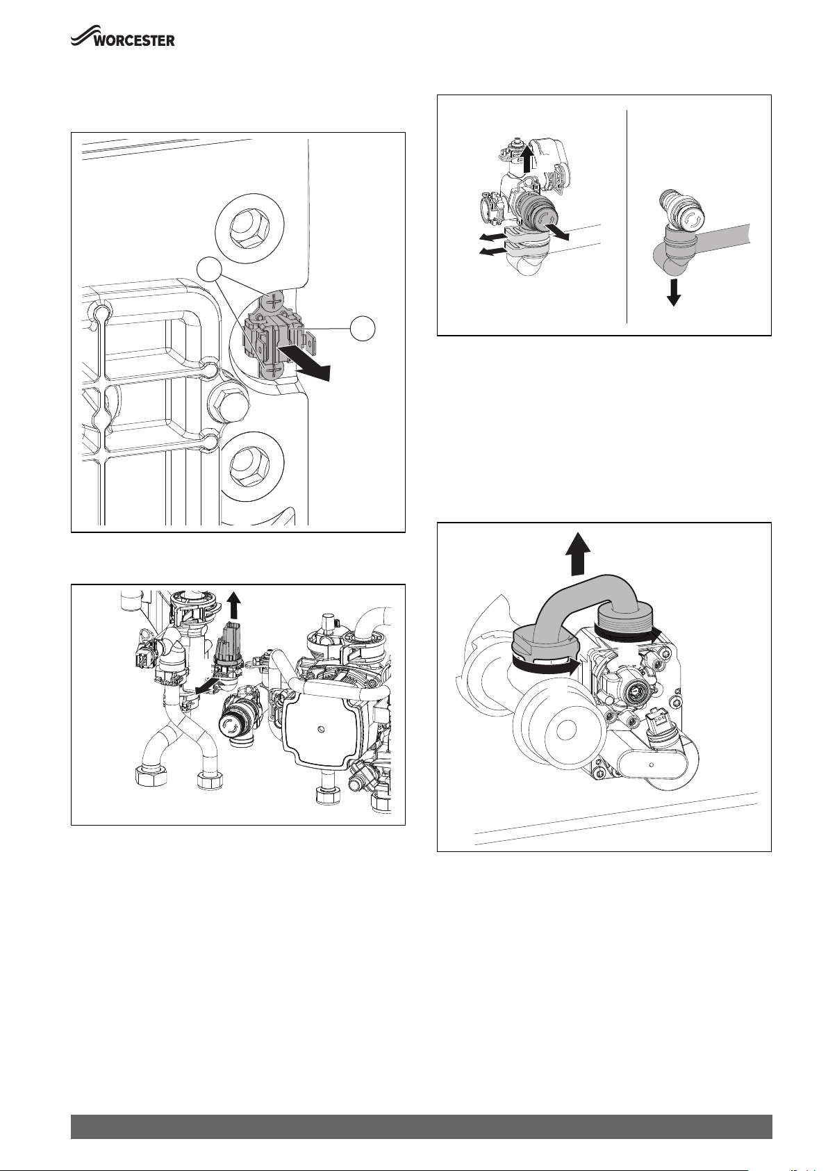
Replacement parts
9.2 Overheat thermostat removal
▶ Remove two electrical connectors from thermostat.
▶ Unscrew [1] the sensor [2].
1
Fig. 98 Removing overheat thermostat
2
0010019116-001
9.4 Pressure relief valve removal
1.
2.
3.
4.
0010023622-001
▶ Open the cover Fig. 54.
▶ Remove the condensate trap Fig. 90.
▶ Pull the spring up [1].
▶ Press the PRV Pipe down lightly [2].
▶ Remove the Pressure relief valve [3].
9.5 Replacing the gas valve
▶ Close the gas isolator.
1. Unscrew the bayonet connection.
2. Unscrew the union nut.
3. Remove the gas pipe.
9.3 Pressure sensor removal
2.
1.
▶ Open the cover Fig. 54.
▶ Remove the condensate trap Fig. 90.
▶ Pull the spring forward [1].
▶ Remove the pressure sensor[2].
3.
2.
1.
0010023621-001
0010017782-001
Fig. 99 Removing the gas pipe
Greenstar 8000 Style – 6720883855 (2019/01)
65

Replacement parts
1. Unplug the plug.
2. Unscrew the union nut.
1.
2.
Fig. 100 Unplugging the plug and unscrewing the union nut
1. Remove the 2 screws.
2. Remove the air/gas ratio control valve.
2.
0010017781-001
9.6 Checking/replacing the motor of the 3-way valve
▶ Check the motor in the Menu > Function check > Activate test > 3-way
valve.
▶ Check/replace the motor of the 3-way valve in the Service menu >
Special function > 3-WV mid. pos. > Yes.
1. Pull out the motor.
2. Press the cable retaining clip.
3. Unplug the plug.
1.
3.
2.
Fig. 102 Removing the motor of the 3-way valve
9.7 Replacing the optional 3-way valve
▶ Remove the screws.
▶ Pull out the 3-way valve.
▶ Press the cable retaining clip.
▶ Unplug the plug.
1.
001001
7784-
001
1.
0010007251-001
Fig. 101 Removing the gas control valve
▶ Install the air/gas ratio control valve in reverse order, and check the
gas/air ratio.
2.
1.
3.
Fig. 103 Removing the 3-way valve
9.8 Following inspection/maintenance
▶ Re-tighten all the threaded connections that have been released.
▶ Restart the appliance.
▶ Check tightness of all joints.
▶ Check the gas/air ratio.
▶ Fit the combustion casing, side-, top panels and front cover.
4.
0010017783-001
66
Greenstar 8000 Style – 6720883855 (2019/01)
10 Fault finding and diagnosis
This fault finding information is for guidance only. Worcester cannot be
held responsible for costs incurred by persons not deemed to be
competent.
This fault finding system assumes that the appliance has been operating
normally until the time of failure (i.e. not a first time installation error).
Basic checks
• Ensure that there is 230V power supply and the polarity is correct to
the appliance.
• Ensure that the appliance settings and functionality is correct.
• Ensure the CH/DHW programmer/timer is functioning.
10.1 Operating and fault displays
Fault finding and diagnosis
• Ensure the room thermostat is functioning.
• Ensure the cylinder thermostat (if fitted) is functioning.
• Ensure the cold water mains is turned on?
• Ensure the primary system has adequate pressure/system content
for the system type.
• Ensure there is gas to the appliance?
– Are other gas appliances working, gas cooker/hob for example?
– Has the credit run out on the gas pre-payment meter?
NOTICE:
On completion of the Service/Fault-Finding task which has required the
breaking and remaking of electrical connections, check:
▶ Earth continuity,
▶ Short circuit check,
▶ Polarity
▶ Resistance to earth.
10.1.1 General information
• Fault code: indicates the fault.
• Fault category: indicates the fault and its effects.
Fault category O (operating code)
Operating codes indicate the operating conditions in normal operation.
Fault category B (blocking faults)
Blocking faults result in the heating system being shut down temporarily.
The heating system restarts automatically as soon as the blocking fault is
removed.
10.1.2 Fault code table
Fault text on the display, description Remedy
Fault
code
Fault
category
200 O Boiler in heating mode –
201 O Boiler in hot water mode –
202 O Boiler in anti-cycle mode –
203 O Boiler in standby, no heat energy demand –
204 O Current prim. water temp. higher than set
val.
208 O Chimney sweep demand –
224 V Safety temp. limiter has tripped 1. Open the closed valve in the heating circuit.
227 V No flame signal after ignition 1. Open the gas isolator.
228 V Flame signal without flame present 1. Replace the air/gas ratio control valve.
305 O Boiler in hot water anti-cycle mode –
–
2. Top up water until the preset pressure is reached.
3. Connect the plug correctly to the safety temperature limiter.
4. Replace the safety temperature limiter.
2. Change the gas installation.
3. Replace the control unit/burner control unit.
4. Replace the ignition electrode.
5. Replace the monitoring electrode.
6. Replace the ignition cable.
7. Replace the ionisation cable.
8. Replace the air/gas ratio control valve.
9. Correct the burner setting.
2. Replace the ionisation cable.
3. Replace the control unit/burner control unit.
Fault category V (locking faults)
Locking faults result in the heating system being shut down, and the
system can only be restarted after a reset.
▶ Press the and keys, until Reset is displayed.
The appliance resumes operation.
If a fault persists:
▶ Rectify the fault according to 10.1.2 Fault code table
Fault category W (maintenance codes)
Greenstar 8000 Style – 6720883855 (2019/01)
67

Fault finding and diagnosis
Fault text on the display, description Remedy
Fault
code
Fault
category
306 V Flame signal after closing the fuel supply 1. Replace the air/gas ratio control valve.
2. Replace the ionisation cable.
3. Replace the control unit/burner control unit.
815 B Low loss header temp. sensor faulty 1. Check the sensor port.
2. Check the differential sensor for incorrect installation position or breakage.
1017 W Water pressure too low 1. Top up water and vent the system.
2. Replace the pressure sensor.
1022 B Hot water storage temperature sensor is
defective
1. Connect the plug to the hot water temperature sensor correctly.
2. Mount the hot water temperature sensor correctly.
3. Replace the hot water temperature sensor.
4. Replace the connecting lead to the hot water temperature sensor.
1065 B Pressure sensor defective or not connected 1. Connect the plug to the pressure sensor correctly.
2. Replace the connecting lead to the pressure sensor.
3. Replace the pressure sensor.
4. Replace the control unit.
1068 W Outside temperature sensor defective Check the connecting lead.
1075 W Short circuit of the temperature sensor at
the heating block
1. Replace the temperature sensor.
2. Replace the connecting lead to the temperature sensor.
3. Replace the control appliance.
1076 W No signal from the temperature sensor at
the heating block available
1. Replace the temperature sensor.
2. Replace the connecting lead to the temperature sensor.
3. Replace the control unit.
2920 V Fault in flame monitoring –
2927 B Flame failed during burner operation 1. Open the main shut-off valve.
2. Open the appliance shut-off valve.
3. Shut down the appliance and check the gas line.
4. Signal evaluation on printed circuit board defective.
5. Replace the ionisation electrode.
6. Establish protective conductor connection (PE) in the control unit.
7. Replace the ignition cable.
8. Replace the connecting lead to the ionisation electrode.
9. Replace the air/gas ratio control valve.
10.Set the burner correctly.
11.Set the burner at minimum rated load.
12.Convert the flue system.
13.The interconnected room air supply is too small or the size of the ventilation
opening is too small.
14.Clean the heating block on the flue gas side.
15.Replace the control unit/burner control unit.
2946 V Incorrect code plug detected Replace the coding plug.
2948 B No flame signal with low output The burner starts automatically after cleaning.
1. If the fault occurs repeatedly: check the settings of the CO2 values.
2950 B No flame signal following starting procedure The burner starts automatically after cleaning.
1. Set the correct gas/air ratio correctly.
2963 B Signal from flow and heat exchanger
Connect the connecting lead correctly.
temperature sensor outside the permissible
range
2964 B Flow rate in heat exchanger too low –
2965 B Flow temperature too high –
2966 B Flow temperature rise in heat exchanger too
–
rapid
2967 B Flow/ heate exchanger temperature sensor
–
differential too great
68
Greenstar 8000 Style – 6720883855 (2019/01)
Environmental protection and disposal
Fault text on the display, description Remedy
Fault
code
Fault
category
2970 B Pressure drop in heating system too rapid –
2971 B System pressure too low 1. Vent the heating system.
2. Top up water until the preset pressure is reached.
3. Replace the cable to the pressure sensor.
4. Replace the pressure sensor.
Table 24 Indicators and fault displays
10.1.3 Faults that are not displayed
Appliance faults Remedy
Combustion noises too loud; rumbling noises ▶ Check the gas type.
▶ Check the gas supply pressure.
▶ Check the flue system; clean or repair if required.
▶ Check the gas/air ratio.
▶ Check the air/gas ratio control valve; replace if required.
Flow noises ▶ Set the pump rate or pump characteristic map correctly and match to the maximum
output.
Heat-up takes too long. ▶ Set the pump rate or pump characteristic map correctly and match to the maximum
output.
Flue gas values incorrect; CO content too high. ▶ Check the gas type.
▶ Check the gas supply pressure.
▶ Check the flue system; clean or repair if required.
▶ Check the gas/air ratio.
▶ Check the air/gas ratio control valve; replace if required.
Violent ignition, poor ignition. ▶ Check the ignition transformer with service function t01 for misfiring, replace if
required.
▶ Check the gas type.
▶ Check the gas supply pressure.
▶ Check the power supply.
▶ Check the electrodes with cable; replace if required.
▶ Check the flue system; clean or repair if required.
▶ Check the gas/air ratio.
▶ For natural gas: check the external gas flow monitor, replace if required.
▶ Check the burner, replace if required.
▶ Check the air/gas ratio control valve; replace if required.
Condensate in air box ▶ Check the non-return valve in the mixing appliance, replace if required.
Combi boilers: hot water outlet temperature is not
reached.
Combi boilers: DHW volume is not reached. ▶ Check the plate heat exchanger.
No function, the display remains dark. ▶ Check the electrical wiring for damage.
Table 25 Faults that are not shown on the display
▶ Check the turbine, replace if required.
▶ Check the gas/air ratio.
▶ Replace defective cables.
▶ Check the fuse, replace if required.
11 Environmental protection and disposal
Environmental protection is a fundamental corporate strategy of the
Bosch Group.
The quality of our products, their economy and environmental safety are
all of equal importance to us and all environmental protection legislation
and regulations are strictly observed.
We use the best possible technology and materials for protecting the
environment taking account of economic considerations.
Packaging
Where packaging is concerned, we participate in country-specific
recycling processes that ensure optimum recycling.
All of our packaging materials are environmentally compatible and can be
recycled.
Greenstar 8000 Style – 6720883855 (2019/01)
Used appliances
Used appliances contain valuable materials that can be recycled.
The various assemblies can be easily dismantled. Synthetic materials are
marked accordingly. Assemblies can therefore be sorted by composition
and passed on for recycling or disposal.
Used electrical and electronic appliances
Electrical or electronic devices that are no longer
serviceable must be collected separately and sent for
environmentally compatible recycling (in accordance with
the European Waste Electrical and Electronic Equipment
Directive).
69
Technical Specifications/Logs
To dispose of old electrical or electronic devices, you should use the
return and collection systems put in place in the country concerned.
Batteries must not be disposed together with your household waste.
Used batteries must be disposed of in local collection systems.
12 Technical Specifications/Logs
12.1 Technical data
12.1.1 Specifications System
Greenstar 8000 Style
GR8700iW 30 GR8700iW 35
Unit Natural gas Propane
Gas flow maximum rate – 10 minutes from lighting
Natural Gas
2)
m3/h 3.2 – 3.6 –
Propane Gas (LPG) kg/h – 2.3 – 2.7
Central Heating (CH)
Maximum rated heat input (net) (Q
) kW 30.2 30.2 34.4 34.4
max
Maximum rated heat output 40/30 °C kW 31.2 31.2 35.2 35.2
Maximum rated heat output 50/30 °C (P
Maximum rated heat output 80/60 °C (P
Minimum rated heat input (net) (Q
) kW 3.0 3.0 5.1 5.1
min
) kW 31.0 31.0 35.0 35.0
cond, max
) kW 29.6 29.6 33.7 33.7
max
Minimum rated heat output 40/30 °C kW 3.3 3.3 5.5 5.5
Minimum rated heat output 50/30 °C (P
Minimum rated heat output 80/60 °C (P
) kW 3.2 3.2 5.5 5.5
cond, min
) kW 2.9 2.9 5.0 5.0
min
Maximum flow temperature °C 70 70 70 70
Maximum flow temperature possible °C 82 82 82 82
Maximum permissible operating pressure (PMS) bar 2.5 2.5 2.5 2.5
Available pump head at 20 K ( °C) system temperature rise m 2.0 2.0 2.0 2.0
Flue
Flue gas temperature 80/60 °C, max/min load °C 67/56 67/56 72/56 72/56
Flue gas temperature 40/30 °C, max/min load °C 49/31 49/31 52/31 52/31
CO2 level at max. rated heat output (after 10 minutes) % 9.5 10.8 9.5 10.8
level at min. rated heat output (after 10 minutes) % 8.6 10.2 8.6 10.2
CO
2
NOx class – 6 6 6 6
NO
rating (EN 15502-1) mg/kWh ≤ 40 ≤ 40 ≤ 40 ≤ 40
x
Condensate
Maximum condensate rate l/h 3.5 3.5 4.1 4.1
pH value, approx. – 4.5 – 5.0 4.5 – 5.0 4.5 – 5.0 4.5 – 5.0
Electrical
Electrical power supply voltage a.c. V 230 230 230 230
Frequency Hz 50 50 50 50
Maximum power consumption (running) W 150 150 108 108
Maximum power consumption (stand-by) W 1 1 1 1
Energy efficiency index (EEI) heating pump – ≤ 0.23 ≤ 0.23 ≤ 0.23 ≤ 0.23
General data
Expansion vessel capacity l 10.0 10.0 10.0 10.0
Expansion vessel pre-charge pressure bar 1.0 1.0 1.0 1.0
Appliance protection rating
3)
IP X4D X4D X4D X4D
Permissible ambient temperature short time/long time °C 0–50/40 0–50/40 0–50/40 0–50/40
Nominal capacity of the appliance l 5.2 5.2 5.2 5.2
Total packaged weight kg 54 54 54 54
Total appliance weight (excluding packaging) kg 46 46 46 46
Lift weight (without front and side panels) kg 40 40 40 40
1) Propane/butane mixture for fixed containers with capacity up to 15 000 l.
2) The Gas Rate provided assumes the accepted NG average calorific value of 34-9 MJ/m3 net.
3) Protection rating may change depending on the control unit/s used on this appliance.
1)
Natural gas Propane
1)
Table 26 GR8700iW 30/35
70
Greenstar 8000 Style – 6720883855 (2019/01)

Technical Specifications/Logs
12.2 Ionisation current
When the burner is running at a minimum rated heat
Type Gas type OK Faulty
GR8700iW 30 S Natural gas ≥ 3 A < 3 A
LPG ≥ 3 A < 3 A
GR8700iW 35 S Natural gas ≥ 7 A < 7 A
LPG ≥ 10 A < 10 A
Table 27 Ionisation current
12.3 Component resistance characteristics
12.3.1 Sensor values
Temperature [°C ± 10 %] Resistance []
-20 2 392
-16 2 088
-12 1 811
-8 1 562
-4 1 342
0 1 149
4 984
8 842
12 720
16 616
20 528
24 454
Table 28 Outside temperature sensor (for weather-compensated control
units, accessory)
Temperature [°C ± 10 %] Resistance []
20 14 772
25 11 981
30 9 786
35 8 047
40 6 653
45 5 523
50 4 608
55 3 856
60 3 243
65 2 744
70 2 332
75 1 990
80 1 704
85 1 464
90 1 262
95 1 093
100 950
Table 29 Flow temperature sensor
12.5 Pump characteristic map of the heating pump
H / m
8
7
6
5
4
3
2
1
0
0
Fig. 104 Pump characteristic maps and pump curves
[1] Pump characteristic map, constant pressure 150 mbar
[2] Pump characteristic map, constant pressure 200 mbar
[3] Pump characteristic map, constant pressure 250 mbar
[4] Pump characteristic map, constant pressure 300 mbar
[5] Pump characteristic map, constant pressure 350 mbar
[6] Pump characteristic map, constant pressure 400 mbar
[A] Pump curve at maximum pump rate
[B] Pump curve at minimum pump rate
H Residual head
V Flow rate
A
6
5
4
3
2
B
300 600 900 1200
1
V / l/h
1800
1500
0010012467-001
12.4 Code plug
Type Gas type Number
GR8700iW 30 S NG Natural gas 20022
GR8700iW 35 S NG Natural gas 20023
Table 30 Coding plug
Greenstar 8000 Style – 6720883855 (2019/01)
71
Technical Specifications/Logs
12.6 Setting values for central heating/DHW output
G20
(20 mbar)
Gross
H
[kWh/m3] 11.2
S(0 °C)
calorific
value
Net calorific
H
[kWh/m3] 9.5
i(15 °C)
value
Performance
[kW]
Load [kW] Display [%] Gas volume
[l/min at T
= 80/60 °C]
4.9 5.1 17 9
6.0 6.3 21 11
7.0 7.3 24 13
8.0 8.4 28 15
9.0 9.5 31 17
10.0 10.6 35 19
11.0 11.7 39 21
12.0 12.8 42 22
13.0 13.9 46 24
14.0 15.0 50 26
15.0 16.2 54 28
16.0 17.3 57 30
17.0 18.5 61 32
18.0 19.6 65 34
19.0 20.8 69 36
20.0 21.9 73 38
21.0 23.1 77 41
22.0 24.3 80 43
23.0 25.5 84 45
24.0 26.7 88 47
25.0 27.9 92 49
26.0 29.1 96 51
26.9 30.2 100 53
Table 31 GR8700iW 30 S NG
V/TR
Gross
H
[kWh/m3] 11.2
S(0 °C)
calorific
value
Net calorific
H
[kWh/m3] 9.5
i(15 °C)
value
Performance
[kW]
Load [kW] Display [%] Gas volume
6.1 6.3 18 11
7.0 7.2 21 13
8.0 8.3 24 15
9.0 9.3 27 16
10.0 10.3 30 18
11.0 11.3 33 20
12.0 12.4 36 22
13.0 13.4 39 23
14.0 14.4 42 25
15.0 15.4 45 27
16.0 16.5 48 29
17.0 17.5 51 31
18.0 18.5 54 32
19.0 19.5 57 34
20.0 20.5 60 36
21.0 21.6 63 38
22.0 22.6 66 40
23.0 23.6 69 41
24.0 24.6 72 43
25.0 25.6 74 45
26.0 26.6 77 47
27.0 27.6 80 49
28.0 28.7 83 50
29.0 29.7 86 52
30.0 30.7 89 54
31.0 31.7 92 56
32.0 32.7 95 57
33.0 33.7 98 59
33.7 34.4 100 60
Table 32 GR8700iW 35 S NG
G20
(20 mbar)
[l/min at T
= 80/60 °C]
V/TR
72
Greenstar 8000 Style – 6720883855 (2019/01)
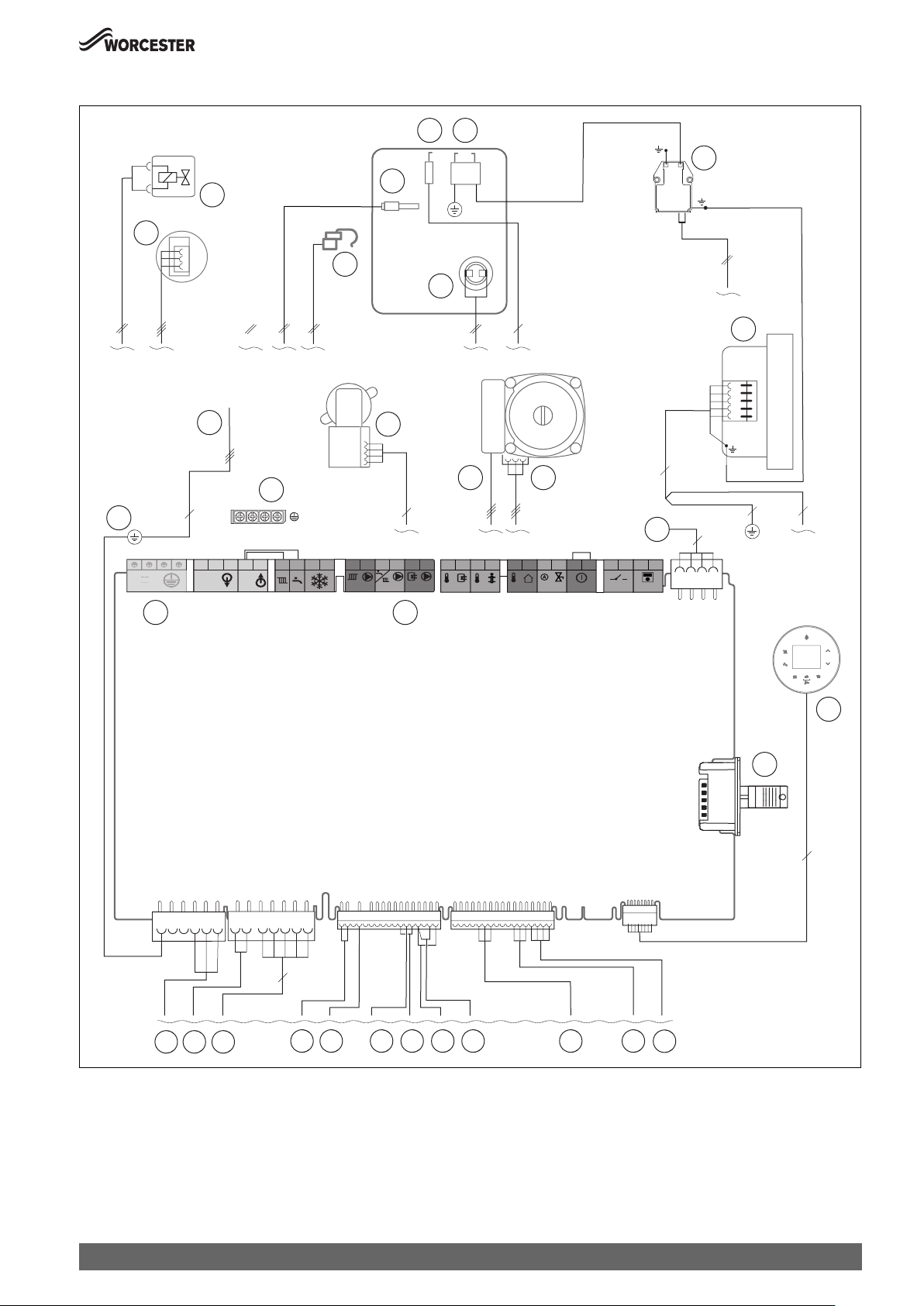
12.7 Electrical wiring
PE
2
1
Technical Specifications/Logs
5 6
8
4
3
7
9
18
PE
20
17
230V
IN
19
LR
LN
NN
L
230V
OUT
LR
FS
L
FR
N
PC0
16
L
15
6
11
4
N
PW1PW2
121
L
TW1
2
T0
10
12121
T1
LF0
5
12
2
121
2
I3
BUS
I1
4
13
14
8
5
11
2
9
8
5
6
4
3
7
1
10
16
0010023666-001
Fig. 105 Electrical wiring
[1] Pressure sensor
[2] Air/gas ratio control valve
[3] Flow temperature sensor at flow pipe
[4] Flow temperature sensor at heating block
[5] Flame sensing electrode
[6] Ignition electrode
[7] Heating block temperature limiter
Greenstar 8000 Style – 6720883855 (2019/01)
[8] Ignition transformer
[9] Fan
[10] Control cable of the heating pump
[11] Heating pump 230 V
[12] Connecting lead for KEY slot
[13] Display
[14] Code plug
73

Technical Specifications/Logs
[15] Terminal strip for external accessories ( terminal assignment
Tab. 13)
[16] 3-way valve (Accessory)
[17] Connecting lead
[18] Earth (PE)
[19] Earth bar
[20] Not used
74
Greenstar 8000 Style – 6720883855 (2019/01)

Technical Specifications/Logs
12.8 Gas boiler system commissioning checklist
This Commissioning checklist is to be completed in full by the competent person who commissioned the appliance as a means of demonstrating compliance
with the appropriate Building Regulations and then handed to the customer to keep for future reference.
Failure to install and commission according to the manufacturer’s instructions and complete this Benchmark Commissioning Checklist will invalidate the warranty. This
does not affect the customer’s statutory rights.
Customer name: Telephone number:
Address:
Boiler make and model
Boiler serial number:
Commissioned by (PRINT NAME): Gas Safe register number:
Company name: Telephone number:
Company address:
Commissioning date:
To be completed by the customer on receipt of a Building Regulations Compliance Certificate*
Building Regulations Notification Number (if applicable):
Controls: Tick the appropriate boxes
Time and temperature control to heating Room thermostat and programmer/timer Programmable room thermostat
Load/Weather compensation Optimum start control
Time and temperature control hot water Cylinder thermostat and programmer/timer Combination boiler
Heating zone valves Fitted Not required
Hot water zone valves Fitted Not required
Thermostatic radiator valves Fitted Not required
Automatic by-pass valve fitted to system Fitted Not required
Boiler interlock Provided
All Systems
The system has been flushed and cleaned in accordance with BS7593 and boiler manufacturer’s instructions Yes
What system cleaner was used?
What inhibitor was used? Quantity litres
Has a primary water system filter been installed? Yes No
The condensate drain has been installed in accordance with the manufacturer’s instructions and/or BS5546/BS6798 Yes
CENTRAL HEATING MODE measure and record
Gas rate m3/hr OR ft3/hr
Burner operating pressure (if applicable) mbar OR Gas inlet pressure mbar
Central heating temperatures Flow temperature °C Return temperature °C
COMBINATION BOILERS ONLY
Is the installation in a hard water area (above 200ppm)? Yes No
If yes, and if required by the manufacturer, has a water scale reducer been fitted? Yes No
What type of scale reducer has been fitted?
HOT WATER MODE measure and record
Gas rate m3/hr OR ft3/hr
Burner operating pressure (if applicable) mbar OR Gas inlet pressure mbar
Cold water inlet temperature °C
Hot water has been checked at all outlets Yes Temperature °C
Water flow rate l/min
All INSTALLATIONS - Record the following:
Flue integrity check: Pass At max. rate: CO ppm AND CO/CO2 Ratio
Fail At max. rate: (where possible) CO ppm AND CO/CO2 Ratio
The heating and hot water system complies with the appropriate Building Regulations Yes
The boiler and associated products have been installed and commissioned in accordance with the manufacturer’s instructions Yes
The operation of the boiler and system controls have been demonstrated to and understood by the customer Yes
The manufacturer’s literature, including Benchmark Checklist and Service Record, has been explained and left with the customer Yes
Commissioning Engineer’s Signature
Customer’s Signature
(To confirm satisfactory demonstration and receipt of manufacturer’s literature)
* All installations in England and Wales must be notified to Local Authority Building Control (LABC) either directly or through
a Competent Persons Scheme. A Building Regulations Compliance Certificate will then be issued to the customer.
www.centralheating.co.uk
Greenstar 8000 Style – 6720883855 (2019/01)
75

Technical Specifications/Logs
12.9 Inspection and maintenance checklist
9
8
6
4.8
4.7
4.6
4.5
4.4
4.3
4.2
4.1
4
3
2
1
Gas Safe Engineers Signature
________________________ ___________________
________________________ ___________________
________________________ ___________________
Gas Safe registration number
Appliance left to customer settings
Gas Safe/Benchmark documentation updated
Check flue integrity
Fit casing
Check flame failure appliance
Gas rate appliance at maximum output in test mode
Check combustion settings: Min/Max test modes
Flue gas analysis
Yes
Yes
Yes
Yes
Yes
Yes
Yes
Yes
Yes
Yes
Yes
Yes
Yes
Yes
Yes
Yes
Yes
Yes
Yes
Yes
Yes
Yes
Yes
Yes
Yes
Yes
Yes
Yes
Correct working gas inlet pressure
Check and clean syphon
was cleaning required?
Check Fan pressure test
Appliance performance checks:
Internal visual inspection
Check for signs of leaking, corrosion and distress
Yes
Yes
No
Yes
Yes
Yes
Yes
Yes
Yes
Yes
Yes
Yes
Yes
No
No
No
Yes
Yes
Yes
Yes
Yes
Yes
Yes
Yes
Visual Inspection:-
Check compliance of appliance, system and components
Check appliance operation (CH & DHW) and fault history
Date:
Inspection and maintenance checklist
Yes
Yes
Year 1
Yes
Yes
Year 2
Yes
Yes
Year 3
Yes
Yes
Year 4
________________________ ___________________
________________________ ___________________
________________________ ___________________
________________________ ___________________
________________________ ___________________
________________________ ___________________
________________________ ___________________
________________________ ___________________
________________________ ___________________
________________________ ___________________
Yes
Yes
Yes
Yes
Yes
Yes
Yes
Yes
Yes
Yes
Yes
Yes
Yes
Yes
Yes
Yes
Yes
Yes
Yes
Yes
Yes
Yes
Yes
Yes
Yes
Yes
Yes
Yes
Yes
Yes
Yes
Yes
Yes
Yes
Yes
Yes
Yes
Yes
Yes
Yes
Yes
Yes
Yes
Yes
Yes
Yes
Yes
Yes
Yes
Yes
Yes
Yes
Yes
Yes
Yes
Yes
Yes
Yes
Yes
Yes
Yes
Yes
Yes
Yes
Yes
Yes
Yes
Yes
Yes
Yes
Yes
Yes
Yes
Yes
Yes
Yes
Yes
Yes
Yes
Yes
Yes
Yes
Yes
Yes
Yes
Yes
Yes
Yes
Yes
Yes
Yes
Yes
Yes
Yes
Yes
Yes
Yes
Yes
Yes
Yes
No
No
No
No
No
No
No
No
No
No
Yes
Yes
Yes
Yes
Yes
Yes
Yes
Yes
Yes
Yes
Yes
Yes
Yes
Yes
Yes
Yes
Yes
Yes
Yes
Yes
Yes
Yes
Yes
Yes
Yes
Yes
Yes
Yes
Yes
Yes
Yes
Yes
Yes
Yes
Yes
Yes
Yes
Yes
Yes
Yes
Year 5
Year 6
Year 7
Year 8
Year 9
Year 10
Year 11
Year 12
Year 13
Year 14
________________________ ___________________
________________________ ___________________
Table 33 Inspection and maintenance checklist
76
Yes
Yes
Yes
Yes
Yes
Yes
Yes
Yes
Yes
Yes
No
Yes
Yes
Yes
Yes
Greenstar 8000 Style – 6720883855 (2019/01)
Year 15

Technical Specifications/Logs
12.10 Service record
It is recommended that your heating system is serviced annually and that the Service record is completed.
Service Provider
Before completing the Service record below, please ensure that you have carried out the service as described in the manufacturer’s instructions.
Always use the manufacturer’s recommended spare parts.
SERVICE 01 Date: SERVICE 02 Date:
Engineer name: Engineer name:
Company name: Company name:
Telephone No: Telephone No:
Gas safe register No: Gas safe register No:
Record At max. rate CO ppm AND CO
At min. rate (Where possible) CO ppm AND CO2 % At min. rate (Where possible) CO ppm AND CO2 %
Comments: Comments:
Signature Signature
SERVICE 03 Date: SERVICE 04 Date:
Engineer name: Engineer name:
Company name: Company name:
Telephone No: Telephone No:
Gas safe register No: Gas safe register No:
Record At max. rate CO ppm AND CO2 % Record At max. rate CO ppm AND CO2 %
At min. rate (Where possible) CO ppm AND CO2 % At min. rate (Where possible) CO ppm AND CO2 %
Comments: Comments:
% Record At max. rate CO ppm AND CO2 %
2
Signature Signature
SERVICE 05 Date: SERVICE 06 Date:
Engineer name: Engineer name:
Company name: Company name:
Telephone No: Telephone No:
Gas safe register No: Gas safe register No:
Record At max. rate CO ppm AND CO2 % Record At max. rate CO ppm AND CO2 %
At min. rate (Where possible) CO ppm AND CO2 % At min. rate (Where possible) CO ppm AND CO2 %
Comments: Comments:
Signature Signature
SERVICE 07 Date: SERVICE 08 Date:
Engineer name: Engineer name:
Company name: Company name:
Telephone No: Telephone No:
Gas safe register No: Gas safe register No:
Record At max. rate CO ppm AND CO2 % Record At max. rate CO ppm AND CO2 %
At min. rate (Where possible) CO ppm AND CO2 % At min. rate (Where possible) CO ppm AND CO2 %
Comments: Comments:
Signature Signature
SERVICE 09 Date: SERVICE 10 Date:
Engineer name: Engineer name:
Company name: Company name:
Telephone No: Telephone No:
Gas safe register No: Gas safe register No:
Record At max. rate CO ppm AND CO2 % Record At max. rate CO ppm AND CO2 %
At min. rate (Where possible) CO ppm AND CO2 % At min. rate (Where possible) CO ppm AND CO2 %
Comments: Comments:
Signature Signature
* All installations in England and Wales must be notified to Local Authority Building Control (LABC) either directly or through a
Competent Persons Scheme. A Building Regulations Compliance Certificate will then be issued to the customer.
www.centralheating.co.uk
Greenstar 8000 Style – 6720883855 (2019/01)
77


TECHNICAL SUPPORT: 0330 123 3366
RENEWABLE SUPPORT: 0330 123 9229
CONTROLS AND CONNECTIVITY TEAM: 0330 123 3641
APPOINTMENTS: 0330 123 9339
SPARES: 0330 123 9779
LITERATURE: 0330 123 9119
TRAINING: 0330 123 0166
SALES: 0330 123 9669
Bosch Thermotechnology Ltd.
Cotswold Way, Warndon
Worcester WR4 9SW
United Kingdom
Tel. 0330 123 9559
worcester-bosch.co.uk
 Loading...