

Bosch Worcester Danesmoor Utility Regular ErP+ 12/18, Worcester Danesmoor Utility System ErP+ 18/25, Worcester Danesmoor Utility Regular ErP+ 18/25, Worcester Danesmoor Utility Regular ErP+ 25/32, Worcester Danesmoor Utility System ErP+ 12/18 Installation, Commissioning And Servicing Instruction Manual
...
UK
Installation, Commissioning and Servicing instruction manual
Floor Standing oil-fired Condensing Boiler Conventional Flue & Room Sealed Flue
Greenstar Danesmoor Utility Regular
ErP+
& Utility System
ErP+
12/18, 18/25, & 25/32
For fully pumped open vent or sealed central heating systems and domestic hot water cylinders
These appliances are for use with Kerosene (Class C2) only.
6 720 821 720 (2018/04)
6720809436-00.1Wo

Contents
Contents
1 Key to symbols and safety instructions . . . . . . . . . . . . . . . . . . . 3
1.1 Key to symbols . . . . . . . . . . . . . . . . . . . . . . . . . . . . . . . . . 3
1.2 General safety instructions . . . . . . . . . . . . . . . . . . . . . . . . 3
2 Installation regulations . . . . . . . . . . . . . . . . . . . . . . . . . . . . . . . . 5
2.1 Complying with the building regulations . . . . . . . . . . . . . 5
3 Appliance information . . . . . . . . . . . . . . . . . . . . . . . . . . . . . . . . . 6
3.1 General information . . . . . . . . . . . . . . . . . . . . . . . . . . . . . 6
3.2 Technical data . . . . . . . . . . . . . . . . . . . . . . . . . . . . . . . . . . 6
3.3 Energy efficiency . . . . . . . . . . . . . . . . . . . . . . . . . . . . . . . . 7
3.4 Layout and components - 18/25 System appliance shown
. . . . . . . . . . . . . . . . . . . . . . . . . . . . . . . . . . . . . . . . . . . . . . 8
3.5 Layout and components - 18/25 Regular appliance shown
. . . . . . . . . . . . . . . . . . . . . . . . . . . . . . . . . . . . . . . . . . . . . 10
4 Pre-Installation . . . . . . . . . . . . . . . . . . . . . . . . . . . . . . . . . . . . . 11
4.1 Cleaning primary systems . . . . . . . . . . . . . . . . . . . . . . . 11
4.1.1 Before cleaning the system: . . . . . . . . . . . . . . . . . . . . . 11
4.1.2 Flushing the system . . . . . . . . . . . . . . . . . . . . . . . . . . . 11
4.1.3 Appliance drain points . . . . . . . . . . . . . . . . . . . . . . . . . 11
4.1.4 Appliance vent points . . . . . . . . . . . . . . . . . . . . . . . . . . 11
4.1.5 Inhibitor . . . . . . . . . . . . . . . . . . . . . . . . . . . . . . . . . . . . . 12
4.1.6 Artificially softened water . . . . . . . . . . . . . . . . . . . . . . . 12
4.2 Mains supply . . . . . . . . . . . . . . . . . . . . . . . . . . . . . . . . . 12
4.2.1 Electrical supply . . . . . . . . . . . . . . . . . . . . . . . . . . . . . . 12
4.3 Oil supply . . . . . . . . . . . . . . . . . . . . . . . . . . . . . . . . . . . . 12
4.3.1 Single pipe gravity feed system: . . . . . . . . . . . . . . . . . . 12
4.3.2 Double pipe sub-gravity feed system: . . . . . . . . . . . . . 13
4.3.3 Single pipe suction lift with de-aerator: . . . . . . . . . . . . 13
4.3.4 Pipework . . . . . . . . . . . . . . . . . . . . . . . . . . . . . . . . . . . . 13
4.3.5 Boiler isolation valve . . . . . . . . . . . . . . . . . . . . . . . . . . . 13
4.4 Water systems and pipework . . . . . . . . . . . . . . . . . . . . 14
4.5 Condensate discharge . . . . . . . . . . . . . . . . . . . . . . . . . 15
4.5.1 Condensate pipe work . . . . . . . . . . . . . . . . . . . . . . . . . 15
4.5.2 Internal connections . . . . . . . . . . . . . . . . . . . . . . . . . . . 16
4.5.3 External connections . . . . . . . . . . . . . . . . . . . . . . . . . . 16
4.6 Pressure relief pipework . . . . . . . . . . . . . . . . . . . . . . . . 18
4.7 Boiler locations and clearances . . . . . . . . . . . . . . . . . . 18
4.8 Flue terminal positions . . . . . . . . . . . . . . . . . . . . . . . . . 19
4.9 Flue options . . . . . . . . . . . . . . . . . . . . . . . . . . . . . . . . . . 21
4.9.1 Conventional flue (CF) . . . . . . . . . . . . . . . . . . . . . . . . . 21
4.9.2 Room sealed flue options . . . . . . . . . . . . . . . . . . . . . . . 22
5 Installation . . . . . . . . . . . . . . . . . . . . . . . . . . . . . . . . . . . . . . . . . 23
5.1 Unpacking the boiler . . . . . . . . . . . . . . . . . . . . . . . . . . . 23
5.2 Pipework positions and flue opening . . . . . . . . . . . . . . 24
5.3 Boiler installation . . . . . . . . . . . . . . . . . . . . . . . . . . . . . 26
5.4 Flue installation . . . . . . . . . . . . . . . . . . . . . . . . . . . . . . . 26
5.4.1 Flue damper installation . . . . . . . . . . . . . . . . . . . . . . . . 27
5.4.2 Installation notes . . . . . . . . . . . . . . . . . . . . . . . . . . . . . . 27
5.5 Combustion chamber (18/25 Regular shown) . . . . . . 28
5.6 Pipework connections . . . . . . . . . . . . . . . . . . . . . . . . . 29
5.7 Oil burner and pump . . . . . . . . . . . . . . . . . . . . . . . . . . . 30
5.8 Refitting components . . . . . . . . . . . . . . . . . . . . . . . . . . 31
5.9 Electrical . . . . . . . . . . . . . . . . . . . . . . . . . . . . . . . . . . . . . 32
6 Commissioning . . . . . . . . . . . . . . . . . . . . . . . . . . . . . . . . . . . . . . 37
6.1 Pre-Commissioning checks - 18/25 Regular shown . . . 37
6.2 Filling the system . . . . . . . . . . . . . . . . . . . . . . . . . . . . . . 37
6.3 Water treatment . . . . . . . . . . . . . . . . . . . . . . . . . . . . . . . 38
6.4 Starting the appliance . . . . . . . . . . . . . . . . . . . . . . . . . . 38
6.4.1 Single pipe gravity feed system: . . . . . . . . . . . . . . . . . . 38
6.4.2 Double pipe sub-gravity feed systems and single pipe
suction lift with de-aerator: . . . . . . . . . . . . . . . . . . . . . . 38
6.4.3 Pump adjustments . . . . . . . . . . . . . . . . . . . . . . . . . . . . . 39
6.4.4 Burner head setting . . . . . . . . . . . . . . . . . . . . . . . . . . . . 40
6.4.5 Boiler lockout indicator on: . . . . . . . . . . . . . . . . . . . . . . 40
6.4.6 Combustion checks . . . . . . . . . . . . . . . . . . . . . . . . . . . . 41
6.4.7 Central heating . . . . . . . . . . . . . . . . . . . . . . . . . . . . . . . . 42
6.5 Finishing commissioning . . . . . . . . . . . . . . . . . . . . . . . . 42
6.5.1 Hand over . . . . . . . . . . . . . . . . . . . . . . . . . . . . . . . . . . . . 43
6.5.2 Appliance guarantee . . . . . . . . . . . . . . . . . . . . . . . . . . . . 43
7 Service and Spares . . . . . . . . . . . . . . . . . . . . . . . . . . . . . . . . . . . 44
7.1 Inspection and service - 18/25 Regular shown . . . . . . . 44
7.2 Pre-service checks . . . . . . . . . . . . . . . . . . . . . . . . . . . . . 44
7.3 Service requirements . . . . . . . . . . . . . . . . . . . . . . . . . . . 45
7.4 Sealed system only . . . . . . . . . . . . . . . . . . . . . . . . . . . . . 45
7.5 Clean the burner . . . . . . . . . . . . . . . . . . . . . . . . . . . . . . . 45
7.6 Oil burner nozzle . . . . . . . . . . . . . . . . . . . . . . . . . . . . . . . 45
7.7 Pump filter . . . . . . . . . . . . . . . . . . . . . . . . . . . . . . . . . . . . 46
7.8 External oil filter . . . . . . . . . . . . . . . . . . . . . . . . . . . . . . . 46
7.9 Combustion chamber - 18/25 Regular shown . . . . . . . 46
7.10 Oil supply system and tank . . . . . . . . . . . . . . . . . . . . . . . 47
7.11 Clean the boiler - Manifold access . . . . . . . . . . . . . . . . . 47
7.12 Re-commissioning the burner . . . . . . . . . . . . . . . . . . . . 47
7.13 After service hand over . . . . . . . . . . . . . . . . . . . . . . . . . . 48
7.14 Spares . . . . . . . . . . . . . . . . . . . . . . . . . . . . . . . . . . . . . . . 48
8 Fault finding and diagnosis . . . . . . . . . . . . . . . . . . . . . . . . . . . . 49
8.1 Burner functions . . . . . . . . . . . . . . . . . . . . . . . . . . . . . . . 49
8.2 Heating and hot water . . . . . . . . . . . . . . . . . . . . . . . . . . . 50
8.3 Boiler function . . . . . . . . . . . . . . . . . . . . . . . . . . . . . . . . . 51
8.4 Logic for the 535 SE/LD RDB control box . . . . . . . . . . . 52
8.5 Riello control box 12/18 model . . . . . . . . . . . . . . . . . . . 53
8.5.3 Fault finding . . . . . . . . . . . . . . . . . . . . . . . . . . . . . . . . . . 53
8.5.4 Flame sensing photocell 12/18 models . . . . . . . . . . . . 55
8.5.5 Flame sensing photocell 18/25 and 25/32 models . . . 55
8.6 Oil supply vacuum testing . . . . . . . . . . . . . . . . . . . . . . . . 55
8.7 Air pressure switch and flue overheat reset . . . . . . . . . 55
8.8 Air pressure h switch connections . . . . . . . . . . . . . . . . . 55
8.9 Oil appliance commissioning checklist . . . . . . . . . . . . . 56
8.10 Service interval record . . . . . . . . . . . . . . . . . . . . . . . . . . 57
Greenstar Danesmoor Utility
ErP+
and Utility System
ErP+
- 6 720 821 720 (2018/04)2
1 Key to symbols and safety instructions
1
Key to symbols and safety instructions
1.1 Key to symbols
Warnings
Warnings in this document are identified by a warning
triangle printed against a grey background.
Keywords at the start of a warning indicate the type and
seriousness of the ensuing risk if measures to prevent
the risk are not taken.
The following keywords are defined and can be used in this document:
• NOTICE indicates a situation that could result in damage to property
or equipment.
• CAUTION indicates a situation that could result in minor to medium
injury.
• WARNING indicates a situation that could result in severe injury or
death.
• DANGER indicates a situation that will result in severe injury or
death.
Important information
This symbol indicates important information where
there is no risk to people or property.
Additional symbols
Symbol Meaning
a numbered step in an action sequence
a step in an action sequence
a reference to a related part in the document or to other
related documents
a reference number to identify or refer to a part or item
List entries, first and second levels
• A single component/item
• A component/list, made up of multiple parts/items.
– Sub component or sublist of main component/list.
–etc.
Abbreviations used in this manual
ØDiameter
CH Central Heating
DHW Domestic Hot Water
DCW Domestic Cold water
TRV Thermostatic Radiator Valve
IP Ingress Protection
CF Conventional Flue
RS Room sealed
N/A Not Allowed
SEDBUK Seasonal Efficiency of Domestic Boilers in the UK
OFTEC Oil Firing Technical Association for the Petroleum Industry
WRAS Water Regulations Advisory Scheme
IET Institute of Engineering and Technology
LABC Local Authority Building Control Body
DWTA Domestic Water Treatment Association
Read these instructions before starting any installation
These instructions are applicable to the Worcester appliance model(s)
stated on the front cove of this manual only and must not be used with
any other make or model of appliance.
The instructions apply in the UK and Eire only and must be followed
except for any statutory obligation.
This appliance must be installed by a competent person, failure to install
correctly could lead to prosecution.
a list entry
a list entry (second level)
Table 1 Symbols
Examples of additional symbols used
A numbered step in an action sequence
A sequence of numbered steps or actions carried out in a specific order
to complete a task.
1. First action
2. Second action
3. Third action
etc.
A step in an action sequence
A sequence of defined actions or steps carried out in order to complete
a task.
▶Action
▶Next action
▶etc
A reference to a related part in the document or to other related
documents.
To refer the reader to a specific figure/table/section within the manual.
e.g. figure 1.
A reference number to identify or refer to a part or item.
In a related figure, items or parts identified by a sequential number.
1.2 General safety instructions
These installation instructions are intended for heating engineers,
plumbers, and electricians.
▶ Read any installation instructions (boiler, heating controls, etc.)
carefully before starting the installation.
▶ Observe the safety instructions and warnings.
▶ Observe national and regional regulations, technical rules and
guidelines.
▶ Record all work carried out.
Oil fumes or leaks from the appliance
If you smell oil fumes, observe the following rules.
▶ Extinguish any naked flames
▶ Isolate the electrical supply
▶ Isolate the fuel supply to the boiler
▶ Open windows and doors
▶ Rectify the fault
Health and safety
The appliance contains no asbestos and no substances have been used
in the construction process that contravene the COSHH Regulations
(Control of Substances Hazardous to Health Regulations 1988). Where
applicable, the CE mark indicates compliance with relative EU
Directives.
Greenstar Danesmoor Utility
ErP+
and Utility System
ErP+
- 6 720 821 720 (2018/04) 3

Key to symbols and safety instructions
Combustible and corrosive materials
Do not store or use any combustible materials (paper, thinners, paints
etc.) inside or within the vicinity of the appliance.
The combustion air must be kept clear of chemically aggressive
substances which can corrode the appliance and invalidate any
warranty.
Handling instructions and guidelines
It is advised that more than one person is involved in the transfer of the
packaged appliance from the van to the point of installation.
It is advised that no attempt should be made to move the packaged
appliance without the use of a suitable truck.
At all times the correct method for handling heavy objects should be
strictly observed.
▶ Lift only a manageable weight, or ask for help.
▶ When lifting, bend the knees, and keep the back straight and feet
apart.
▶ Do not lift and twist at the same time.
▶ Lift and carry items close to the body.
▶ Wear protective clothing and gloves to protect from any sharp edges.
Intended use
This boiler must only be used as a heat appliance in a heating system for
domestic purposes.
Any other use is considered inappropriate. Any damage that results from
such use is excluded from liability.
Appliance operation
This appliance can be used by children aged from 8 years
and above and persons with reduced physical, sensory or
mental capabilities or lack of experience and knowledge, if
they have been given supervision or instruction concerning
the use of the appliance, in a safe way, and understand the
hazards involved.
Children shall not play with the appliance.
Cleaning and user maintenance shall not be made by
children without supervision.
Installation, commissioning and servicing
Installation, commissioning and servicing must only be carried out by a
competent registered engineer.
▶ Only use original spares.
▶ Advise the user to have the system regularly serviced by a
competent, qualified engineer (such as OFTEC registered personnel)
using approved spares, to help maintain the economy, safety and
reliability of the appliance.
Fitting and Modification
Fitting the appliance and any controls to the appliance may only be
carried out by a competent engineer in accordance with these
instructions and the relevant Installation Regulations.
Flue systems must not be modified in any way other than as described in
the fitting instructions.
Any misuse or unauthorised modifications to the appliance, flue or
associated components and systems could invalidate the warranty. The
manufacturer accepts no liability arising from any such actions,
excluding statutory rights.
Electrical work
Electrical work must only be carried out by a qualified electrician.
▶ Before starting electrical work:
– Isolate the mains electrical supply and secure against
unintentional re-connection.
– Check for zero potential.
▶ Also observe connection diagrams of other system components.
Handover to the user
When handing over, instruct the user how to operate the heating system
and inform him about its operating conditions.
▶ Explain how to operate the heating system and draw the user's
attention to any safety-relevant action.
▶ Explain that modifications and repairs must only be carried out by an
authorised contractor.
▶ Advise the user to have the system serviced annually by a competent,
OFTEC registered engineer.
▶ Leave the installation instructions with the completed
commissioning form and the operating instructions with the user or
at the gas meter.
Greenstar Danesmoor Utility
ErP+
and Utility System
ErP+
- 6 720 821 720 (2018/04)4

2 Installation regulations
2.1 Complying with the building regulations
This heating appliance forms part of the controlled services for the
building. It is law that all controlled services for buildings must comply
with building regulations. You must be able to satisfy your Local
Authority Building Control Body (LABC) that the work carried out
concerning the installation and commissioning of this heating appliance
has been carried out to a satisfactory standard.
OFTEC operate a competent persons scheme and registered installers
are able to certify that their work complies with building regulations.
Under the scheme;
• OFTEC must be informed about every installation.
• OFTEC will issue a building regulations compliance certificate to the
householder and will notify the LABC.
OFTEC provide controlled document forms CD10 and CD11 for use
during installation and commissioning respectively.
Other organisations operate self-certification schemes e.g. NAPIT and
BESCA Ltd. and it may be possible for installers who are members of
these organisations to self certify their work.
Alternatively you must submit a building control notice to the LABC
before installing any boiler. The LABC will then arrange regular
inspection visits during the work to ensure that the installation complies
with the regulations.
Installation
Failure to install appliances correctly could lead to prosecution.
The appliance should be installed by a competent person. The person
installing the appliance should be aware of the Health and Safety at Work
Act and take appropriate action to ensure that the regulations are
adhered to. In order to give optimum efficiency and trouble free
operation the appliance must be commissioned by a qualified OFTEC
engineer.
The compliance with a British Standard does not, in itself, confer
immunity from legal obligations. In particular the installation of this
appliance must be in accordance with the relevant requirements of the
following British Standards and regulations in respect of the safe
installation of equipment:
BS 5410: part 1: Code of practice for Oil Fired Boilers.
BS 799: part 5: Specification for Oil Storage Tanks.
BS 7593: Code of Practice for treatment of water in domestic
hot water central heating systems.
BS 5449: part 1: Specification for forced circulation hot water central
heating for domestic premises.
BS 5955: part 8: Specification for the installation of thermoplastic
pipes and associated fittings for use in domestic hot
and cold water services and heating systems.
BS 7291: Thermoplastic pipes and associated fittings for hot
and cold water for domestic purposes and heating
installations in buildings.
BS 7074: part 1: Application, selection and installation of expansion
vessels and ancillary equipment for sealed water
systems.
BS 1254-2: Copper and copper alloys plumbing fittings part 2:
Fittings with compression ends for use with copper
tubes.
BS 7671: IET Wiring Regulations, current edition.
BS 1362: Specification for general purpose fuse links for
domestic and similar purposes.
Installation regulations
The Building Regulations Part G, Part J and L1 England and Wales; Part
F, Part G and Part J Section III Scotland; Part L and Part F Northern
Ireland.
Local water company bye-laws.
The Control of Pollution (Oil) Regulations.
OFTEC Standards.
Where no specific instruction is given, reference should be made to the
relevant codes of practice.
Installations in Eire (Republic of Ireland)
The Installation must be performed by a competent and suitably trained
person in accordance with the following Eire regulations.
Current Building Regulations - Republic of Ireland
ETCI rules for electrical installation
For further guidance see:
OFTEC Technical book three - Regional requirements: Republic of
Ireland
Greenstar Danesmoor Utility
ErP+
and Utility System
ErP+
- 6 720 821 720 (2018/04) 5

Appliance information
6720821720 - 05.1Wo
D
600mm
370mm
855mm
B
C
A
E
3 Appliance information
3.1 General information
Standard package:
A - Floor standing oil fired condensing boiler
B - Literature pack:
• Greenstar Danesmoor Installation, Commissioning and Servicing
instruction manual
• User Instructions
• Fascia information card
• Guarantee registration card
C - BSP plug, one inch (Regular only)
D - ErP label
E - Flue damper
3.2 Technical data
Description Units 12/18 18/25 25/32
Central heating
Central heat output (max) kW 18 25 32
Primary water capacity (total) litres 20 21 22
Maximum static head metres 30 30 30
Minimum static head metres 111
Water side resistance (20°C
difference)
Maximum available pump head
(20°C difference) Utility System
Maximum permissible sealed
system operating pressure in
accordance with WRAS
guidelines
Flue
Exit flue gas mass flow kg/hr 29 40 51
Pipework connections
Fuel line (compression) mm 10 10 10
Flow Utility BSP 1” 1” 1”
Flow Utility System mm 22 22 28
Utility flow and optional vent/air
vent
Return mm 22 22 28
Condensate (Polypropylene) mm 21.5 21.5 21.5
PRV outlet - Utility System mm 15 15 15
Electrical
Electrical power supply voltage ac ..V 230 230 230
Frequency Hz 50 50 50
Thermostats
Boiler flow temperature range
(cut in/cut out)
Control thermostat differential °C 555
Boiler high limit thermostat set
point
Boiler manual reset overheat
thermostat set point
Flue manual reset overheat
thermostat set point
General data
Maximum hearth temperature °C <100 <100 <100
SEDBUK 2009 % 91.1 90.9 90.7
SEDBUK 2005 % 93.2 93.0 92.8
Appliance protection rating IP 20 20 20
Weight (excluding packaging)
Utility Regular
Weight (excluding packaging)
Utility System
mbar 20 30 56
mH2 O 5.2 4.3 4.1
bar 2.5 2.5 2.5
BSP 111
°C 55/81 55/81 55/81
°C 95 95 95
°C 105 105 105
°C 110 110 110
kg 104 108 115
kg 112 112 122
Greenstar Danesmoor Utility
ErP+
and Utility System
ErP+
- 6 720 821 720 (2018/04)6
Appliance information
3.3 Energy efficiency
The following product data satisfy the requirements of the EU Regulations No. 811/2013 and No. 812/2013 supplementing Directive 2010/30/EU.
Product data Symbol Unit 7731600147 7731600151 7731600155 7731600148 7731600152 7731600156
ErP+
Danesmoor
Utility
Regular
18/25
Product type – – Danesmoor
Utility
Regular
12/18
Condensing boiler – – Yes Yes Yes Yes Yes Yes
Low temperature boiler – – No No No No No No
B1 boiler – – No No No No No No
Cogeneration space heater
– – No No No No No No
(CHP)
Combination heater – – No No No No No No
Rated heat output P
Seasonal space heating
η
kW 18 25 32 18 25 32
rated
% 909091909091
s
energy efficiency
Energy efficiency class––AAAAAA
Useful heat output
At rated heat output and
high temperature regime
At 30 % of rated heat output
and low temperature regime
2)
P
1)
P
kW 18.2 25.6 32.3 18.2 25.6 32.3
4
kW 5.7 8.0 10.1 5.7 8.0 10.1
1
Useful efficiency
At rated heat output and
high temperature regime
At 30 % of rated heat output
and low temperature regime
2)
η
1)
η
% 92.6 92.5 92.4 92.6 92.5 92.4
4
% 96.8 96.5 96.4 96.8 96.5 96.3
1
Auxiliary electricity consumption
At full load el
At part load el
In standby mode P
kW 0.158 0.152 0.147 0.158 0.152 0.147
max
kW 0.055 0.054 0.050 0.055 0.054 0.050
min
kW000000
SB
Other items
Standby heat loss P
Ignition burner power
P
kW 0.174 0.121 0.171 0.174 0.121 0.171
stby
kW------
ign
consumption
Emissions of nitrogen
NOx mg/kWh 110 103 109 110 103 109
oxides
Annual energy consumption Q
Sound power level, indoors L
kWh------
HE
dB(A)575654555655
WA
Table 2 Product data for energy consumption
1) High-temperature regime means 60 °C return temperature at heater inlet and 80 °C feed temperature at heater outlet.
2) Low temperature means for condensing boilers 30 °C, for low-temperature boilers 37 °C and for other heaters 50 °C return temperature (at heater inlet).
ErP+
Danesmoor
Utility
ErP+
Regular
25/32
Danesmoor
Utility
ErP+
System
12/18
Danesmoor
Utility
ErP+
System
18/25
Danesmoor
Utility
ErP+
System
25/32
Greenstar Danesmoor Utility
ErP+
and Utility System
ErP+
- 6 720 821 720 (2018/04) 7

Appliance information
27
26
28
30
29
31
1
2
3
4
6
5
7
8
9
10
11
12
13
14
16
17
18
19
20
21
22
23
24
15
25
32
34
33
6720821720-01.1Wo
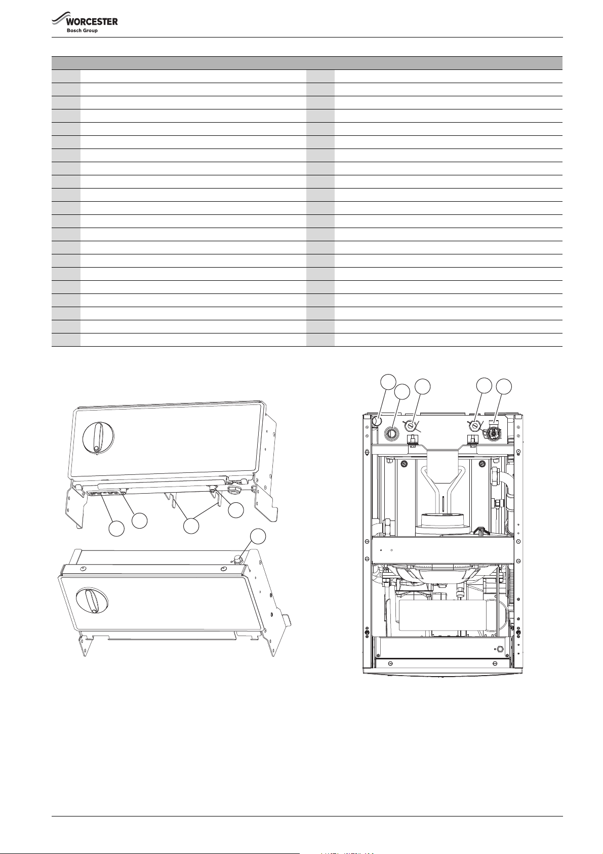
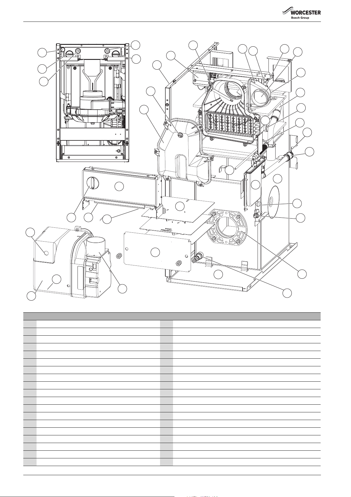
3.4 Layout and components - 18/25 System appliance shown
Fig. 1 System appliance shown
Greenstar Danesmoor Utility
ErP+
and Utility System
ErP+
- 6 720 821 720 (2018/04)8
Appliance information
35
36
37
38
39
6720
821720-03.1Wo
3
41
40
2
1
FRONT
6720821720-04.1Wo
Figure 1 does not include the top, front, left, and right hand side panel
1 Return connection 21 Oil pump (behind plastic cover)
2 Flow connection 22 Burner control box (behind plastic cover)
3 Pressure relief valve 23 Riello RDB burner
4 Air inlet casing 24 Lock out reset button (on the front of the burner control box)
5 Secondary heat exchanger 25 Expansion vessel
6 Secondary heat exchanger baffles 26 Control box assembly
7 Baffle retaining clip 27 Temperature control knob
8 Secondary Heat exchange drain point 28 Flue manifold access cover
9 Condensate discharge 29 Combustion chamber access door (primary baffle inside)
10 Condensate trap 30 Flue gas sampling point
11 Optional oil return position 31 System pressure gauge
12 Oil isolating valve 32 Flue overheat thermostat phial
13 Primary heat exchanger 33 Flue manifold
14 Pump drain point 34 Air pressure switch
15 Burner mount plate 35 Burner lead connector socket
16 Base plate and oil drip tray 36 Flue thermostat reset
17 Circulating pump 37 Expansion vessel retaining bracket
18 Primary heat exchanger drain point 38 High limit thermostat reset
19 Burner air intake 39 Auto reset thermostat
20 Burner motor (behind plastic cover) 40 Control & manual reset overheat thermostat phial
41 Auto-reset high-limit thermostat phial
Table 3 Appliance component details
Fig. 2 Control panel thermostat detail Fig. 3 Top view connections
Greenstar Danesmoor Utility
ErP+
and Utility System
ErP+
- 6 720 821 720 (2018/04) 9
Appliance information
26
27
28
25
2
1
3
4
6
7
8
22
23
20
21
30
31
18
16
17
15
14
12
11
10
9
24
19
13
32
33
34
5
6720821720-02.1Wo
37
36
35
38
39
29
3.5 Layout and components - 18/25 Regular appliance shown
Fig. 4 18/25 Regular appliance shown
1 Control box assembly 20 Oil isolating valve
2 Flue manifold access cover 21 Optional oil return position
3Flue gas sampling point 22 Burner mounting plate
4 Casing side panel 23 Primary heat exchanger drain
5 Air pressure switch 24 Base plate and oil drip tray
6 Flue overheat thermostat phial 25 Burner air intake - connected by flexible duct [10] to air inlet casing [9]
7 Power cable clip 26 Burner motor - behind plastic cover
8 Fire valve sensor clip 27 Oil pump - behind plastic cover
9 Air inlet casing 28 Lockout reset button (on front of burner control box)
10 Flexible air duct (connecting to air intake [25]on burner) 29 Combustion chamber access door
11 Secondary heat exchanger bleed point (one on either side) 30 One piece baffle arrangement
12 Secondary heat exchanger 31 Combustion chamber
13 Heat exchanger flow pipe 32 Boiler overheat reset button
14 Secondary heat exchanger drain 33 Flue overheat reset button
15 Condensate outlet 34 Temperature control knob
16 Condensate trap 35 Return
17 Condensate drain pipe 36 Flow/Optional combined feed and vent
18 Flexible condensate drain pipe connection 37 Control & manual reset overheat thermostat phial
19 Primary heat exchanger 38 Auto-reset high-limit thermostat phial
Figure 4 does not include the top, front, and right hand side panel.
Greenstar Danesmoor Utility
ErP+
and Utility System
ErP+
- 6 720 821 720 (2018/04)10
4 Pre-Installation
6720813284-21.1Wo
1
Pre-Installation
4.1 Cleaning primary systems
DANGER: Danger to life through electric shock!
▶ Before carrying out any work on electrical
components, isolate them from the power supply
(230 V AC) (fuse, circuit breaker) and secure against
unintentional reconnection.
NOTICE: Risk of damage to appliance or accessories!
▶ All the following pre-installation sections must be
read and requirements met before starting the
appliance or flue installations.
NOTICE: Risk of damage to system or appliance!
Debris from the system can damage the appliance and
reduce efficiency. Failure to comply with the guidelines
for the use of water treatment with the appliance will
invalidate the appliance guarantee and contravene the
Building Regulations.
▶ It is a requirement of the Building Services
Compliance Guide which is a second tier document
to the Building Regulations to flush and inhibit the
primary water system in accordance with BS 7593.
▶It is recommended that you fit a primary water
cleanser to the system. Worcester recommends
fitting a filter that will help remove both magnetite
and non-magnetic debris.
4.1.1 Before cleaning the system:
▶ Ensure that the system and pipe work is in good working order.
▶ Where possible keep the existing appliance/circulating pump in
place when flushing the system.
Follow the guidance of BS7593:
Treatment of water in domestic hot water central heating and also the
flushing guidelines below.
4.1.2 Flushing the system
▶ Fill the system with cold water and check for leaks.
▶ Open vented systems only:
– Turn off the water to the system header tank.
▶ Open all drain cocks and drain the system.
– See figure 5 for appliance drain points.
▶ Close drain cocks and add a suitable flushing agent at the correct
strength for the system conditions in accordance with the
manufacturer‘s instructions.
▶ Circulate the flushing agent before the boiler is fired up.
▶ Run the boiler/system at normal operating temperature as directed
by the manufacturer of the flushing agent.
▶ Drain and thoroughly flush the system to remove the flushing agent
and debris.
▶ It may be necessary to use a power flushing machine to aid the
cleansing procedure in some circumstances.
▶ Close the drain cocks and manual air vents.
▶ Add a suitable inhibitor to the system in accordance with the
manufacturers instructions.
▶ Open vented systems only:
– Turn on the water to the system header tank and allow the system
to fill.
▶ Sealed systems only:
– Fill the system to between 1 and 1.5 bar via a WRAS approved
filling loop.
▶ Vent any air from the boiler and system.
– See figure 6 for appliance manual vent points.
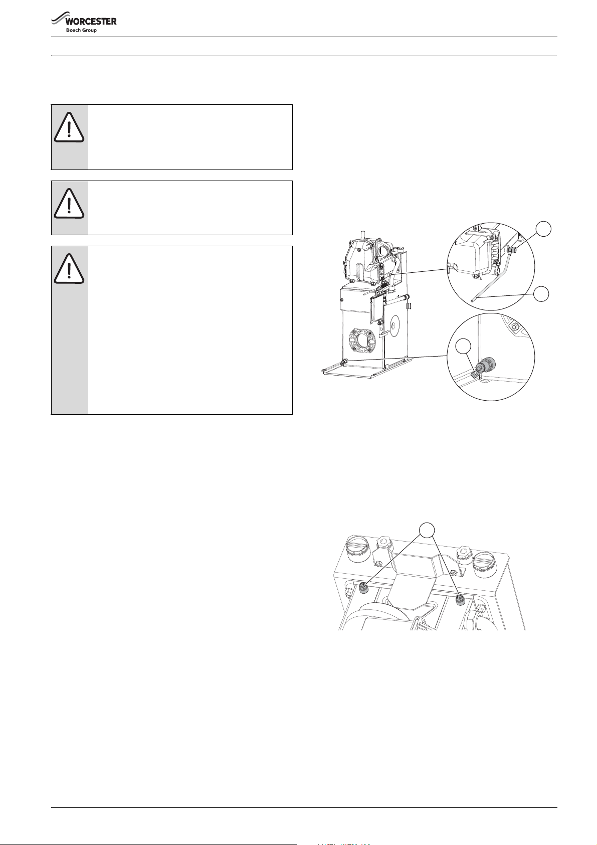
4.1.3 Appliance drain points
▶ The appliance can be drained via the primary heat exchanger point
[3]:
– There is an additional drain point on the secondary heat
exchanger [1].
1
2
3
6720813284-20.1Wo
Fig. 5 Appliance drain points
[1] Secondary heat exchanger drain point.
[2] Secondary heat exchanger drain hose.
[3] Primary heat exchanger drain point.
4.1.4 Appliance vent points
There are two vent points at the top of the secondary heat exchanger.
Only one may be in use, the other may be obscured by side fluing.
▶ Use a radiator key or suitable screwdriver to open the vent point.
Fig. 6 Manual vent points
[1] Manual vent points (each side of the secondary heat exchanger).
Greenstar Danesmoor Utility
ErP+
and Utility System
ErP+
- 6 720 821 720 (2018/04) 11
Pre-Installation
6720813284-08.2Wo
1
2
3 4
300mm
Min.
4m Max.
6 8
53
109
13
7
4.1.5 Inhibitor
Add a suitable inhibitor or combined inhibitor/anti-freeze, if the system
is exposed to freezing conditions, to the heating system in accordance
with the DWTA code of practice and manufacturer‘s guidelines.
The inhibitor or combined inhibitor/anti-freeze must not
cause damage to the materials within the boiler (mild
steel, stainless steel, copper and brass) and any other
materials/components within the system.
▶ The concentration level of inhibitor in the system
should be checked every 12 months or sooner if
system content is lost.
WARNING: Sealing agents
▶ In cases where all attempts to find a system micro
leak have failed, Worcester, Bosch Group supports
the use of Fernox F4 leak sealer.
Water treatment products
Suitable water treatment products can be obtain from the following
manufacturers:
ADEY 01242 546717
www.adey.com
FERNOX 0870 601 5000
www.fernox.com
SENTINEL 0800 389 4670
www.sentinel-solutions.net
4.1.6 Artificially softened water
It is possible to have an ion exchange water softener fitted to the cold
water system of the property. However, the boiler requires an untreated
cold water connection taken from the mains supply, before the water
softener, to the primary water filling point of the heating system.
Alternatively there are water softening/treatment devices that do not
adjust or alter the pH levels of the water. With these devices it may not
be necessary to provide an untreated water by-pass to the primary water
filling point of the heat system.
NOTICE:
▶ Salt based, softened water must not be used to fill
the central heating system.
4.3 Oil supply
NOTICE: Contaminated oil supplies can damage the
appliance.
Failure to ensure that the oil supply is clear of
contaminants may invalidate the appliance warranty.
▶ Ensure the oil supply is free of contaminates and
measures are taken to prevent contamination of the
appliance.
• This appliance is suitable for Kerosene (Class C2) only, no other
fuel must be used.
• Plastic or steel tanks should be installed to BS 5410.
A steel tank should conform to BS 799: part 5 and have a slope of
1:24 away from the outlet with a sludge cock at the lower end.
• Do not use galvanised steel tanks or pipework for the oil system.
• Do not use soldered joints on the oil supply pipework.
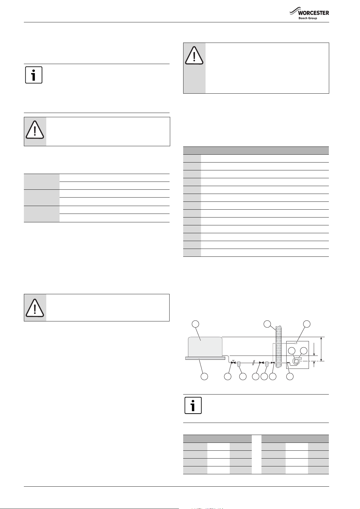
Key to Oil supply illustrations, figures 7, 8 & 9
1OIl storage tank
2 Full base (plastic tank)
3 Isolating valve
4 Oil strainer and water separator
5 Fire valve to BS 5410
6External wall
7 Oil filter (70μm max filtration size)
8 Fire valve sensor
9Oil pump
10 Oil burner
11 Non-return valve
12 De-aerator
13 Appliance isolation valves
Table 4 Key to oil supply feed system
4.3.1 Single pipe gravity feed system:
The oil storage tank [1] must be positioned so that the oil level does not
exceed 4 metres above the level of the burner oil pump [9] and in
addition the oil level must be at least 300mm above the oil pump [9].
Where the maximum oil level in the oil storage tank exceeds 4 metres, a
head breaking device must be installed between the tank [1] and the
burner oil pump [9].
4.2 Mains supply
4.2.1 Electrical supply
• Supply: 230V - 50 Hz
• Cable: PVC insulated 0.75 mm2 (24 x 0.2mm) temperature rated to
90°C.
• External 5A fuse to BS1362.
• The appliance must be earthed.
• This appliance must not be connected to a three phase supply.
• Wiring must comply with the latest IET wiring regulations.
• It must be possible to isolate the appliance from the electrical supply
with at least a 3mm contact separation in both poles supplying the
appliance.
• Wiring between the appliance and the electrical supply must comply
with IET wiring regulations and any local regulations that may apply
for fixed wiring to a stationary appliance.
• Any additional components that are connected to the boiler with
mains electrical supply must not have a separate supply.
Fig. 7 Single pipe feed
All dimensions are in metres unless otherwise stated.
The maximum pipe run figures are based on using
copper pipe with an inside diameter of 2mm less than
the outside diameter.
Maximum pipe run for single pipe gravity fed system
Head (m) 10mmØ 12mmØ Head (m) 10mmØ 12mmØ
0.5 12 30 2.5 62 100
1.0 25 69 3.0 74 100
1.5 37 91 3.5 87 100
2.0 49 100 4.0 99 100
Greenstar Danesmoor Utility
ErP+
and Utility System
ErP+
- 6 720 821 720 (2018/04)12
Pre-Installation
3.5m Max.
150mm
6720813284-09.2Wo
1
2
3 4
73
6 8
5
11
109
13
6720813284-10.2Wo
2
4
3.5m Max.
1 6
12
5
33
7
109
8
13
6720813288-03.1Wo
1
5
4
3
2
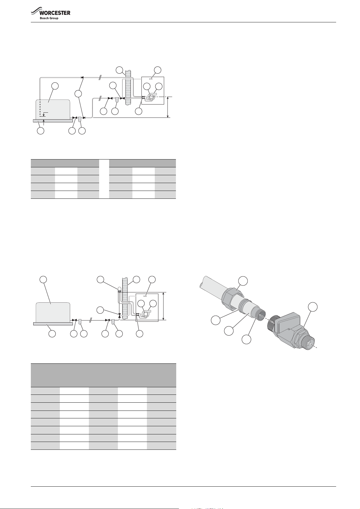
4.3.2 Double pipe sub-gravity feed system:
Maximum suction height 3.5 metres. Non-return valves must be fitted to
the inlet and return oil line between the oil pump [9] and oil storage tank
[1].
Fig. 8 Double pipe feed
Maximum pipe run for double pipe sub-gravity fed system
Head (m) 10mmØ 12mmØ Head (m) 10mmØ 12mmØ
050100 2.0 26 66
0.5 44 100 2.5 20 50
1.0 38 95 3.0 14 37
1.5 32 80 3.5 8 22
4.3.3 Single pipe suction lift with de-aerator:
Maximum suction height 3.5 metres. The oil tank [1] must be positioned
below the oil pump [9]. Create an inlet and return loop between the deaerator [12] and oil pump [9].
A non-return valve must be incorporated within the de-aerator or fitted
to the oil line between the oil storage tank [1] and the de-aerator [12].
A top feed oil tank fitted with a de-aerator using an internal non-return
valve should have any non-return valves fitted in the base of the tank to
the suction line removed to assist purging air from the oil line.
4.3.4 Pipework
▶ Refer to the oil supply sections Single pipe gravity feed
system: 4.3.1, Double pipe sub-gravity feed system: 4.3.2 & Single
pipe suction lift with de-aerator: 4.3.3 for oil supply pipework
configurations.
Oil supply pipework considerations:
• Lay the oil supply pipe as straight and level as possible to avoid air
pockets and unnecessary friction losses.
– Route away from the boiler access door or other hot surfaces.
• Install a manual isolating valve to the oil supply pipe, as close to the
oil storage tank as possible.
• Fit an oil strainer and water separator to the oil supply pipe, near the
oil storage tank.
– Fit an additional oil filter (70 μm max filtration size) close to the
boiler, but not inside the boiler casing.
• Fit a fire valve in accordance with BS 5410.
– The fire valve should be fitted externally to the building with the
fire valve sensor located within the appliance case.
– A fire valve with a shut off temperature of 85°C or higher must be
fitted to avoid the possibility of nuisance shut offs.
– A capillary type valve provides a neat and simple installation.
Alternatively, a fusible link or electrical system may be used.
• Under no circumstances should a combination isolating/fire valve be
used as the sole fire protection device.
4.3.5 Boiler isolation valve
▶ Use copper pipe of the correct diameter according to the information
shown in oil supply sections 4.3.1, 4.3.2 & 4.3.3.
– If using soft copper pipe (R220) with a compression fitting, an
insert must be used to prevent the pipe from collapsing or
distorting when the fitting is tightened.
▶ Slide nut [1] and olive [5] onto the oil supply pipe [4].
▶ Slide insert [3] into the pipe.
▶ Offer the pipe to the fitting [2] and tighten the nut [1].
Fig. 9 De-aerator feed
Maximum pipe run for single pipe suction lift with de-aerator
FUEL FLOW RATE
2.5kg/h 5kg/h 10kg/h 10kg/h
Head (m) 8mmØ 8mmØ 8mmØ 10mmØ
010055 26 100
0.5 95 45 23 100
1.0 80 40 20 90
1.5 70 35 17 75
2.0 60 30 14 65
2.5 45 25 11 50
3.0 35 15 8 35
[NOTE:] The table and illustration above is a guide only and does not in
Greenstar Danesmoor Utility
3.5 25 10 5 20
any way override the de-aerator manufacturer’s instructions
ErP+
and Utility System
Fig. 10 Isolation valve bracket removed for clarity
▶ Use flexible hoses to connect from the boiler isolation valve/s to the
oil pump.
ErP+
- 6 720 821 720 (2018/04) 13
Pre-Installation
6720808218-07.1Wo
4.4 Water systems and pipework
NOTICE:
▶ The boiler should not be allowed to operate with a
return temperature of less than 30°C when the
system is up to operating temperature.
Primary system plastic pipework:
• Any plastic pipework used for the CH system must have a polymeric
barrier, complying with BS 7921 and installed to BS 5955 with
1000mm (minimum) length of copper or steel pipe connected to the
boiler.
• Plastic pipework used for underfloor heating must be correctly
controlled with a thermostatic blending valve limiting the
temperature of the circuits to approximately 50°C with 1000mm
(minimum) length of copper or steel pipe connected to the boiler,
and a 20K differential must be maintained at the appliance.
Primary system/connections/valves:
• Do not use galvanised pipes or radiators.
• All system connections, taps and mixing valves must be capable of
sustaining a pressure of 3 bar.
• Radiator valves should conform to BS 2767:10.
• All other valves should conform to BS 1010.
• An automatic bypass valve must be connected between the heating
flow and return where TRVs are used on all radiators, fitted to give at
least a 3 metre circuit when activated.
• Drain cocks are required at all the lowest points on the system.
• Air vents are required at all high points on the system.
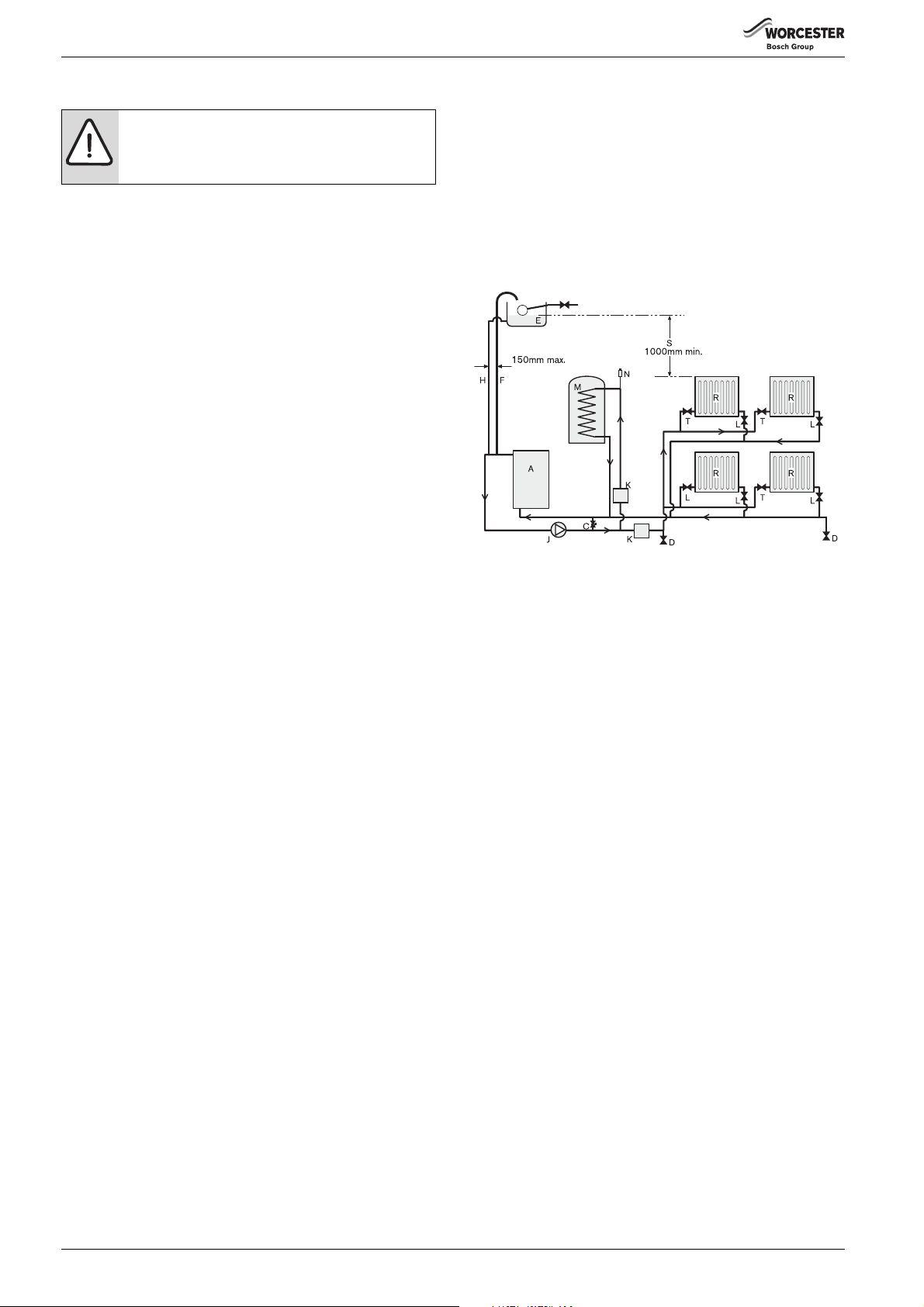
Open vent primary system (Regular only)
• The open vent pipe (F) and feed and expansion pipe (H) must rise
continuously from the appliance.
• The feed and expansion cistern (E) must be positioned to provide a
static head (S) of at least 1 metre above the highest point in the
heating system to the water level in the feed and expansion cistern.
• Ensure adequate space is left in the expansion cistern for expansion
of the system water.
• No valve shall be fitted in the open vent pipe (F) or the feed and
expansion pipe (H).
• The open vent pipe (F) must be at least 22mmØ.
Fig. 11 Regular boiler, open vent layout
[A] Regular appliance
[A1] System appliance
[B] Expansion vessel*
[C] Automatic bypass valve
[D] Drain cock
[E] Feed and expansion cistern
[F] Open vent 22mmØ min.
[G] Pressure gauge*
[H] Feed and expansion 15mmØ min.
[J] Circulating pump*
[K] Zone valves
[K1] Three port valve
[L] Lockshield valve
[M] Hot water cylinder
[N] Automatic air vent
[P] Pressure relief valve*
[P1] Pressure relief discharge*
[R] Radiators
[T] Thermostatic radiator valve TRV
[U] To filling system
[NOTE] * Components included in the System boiler
Greenstar Danesmoor Utility
ErP+
and Utility System
ErP+
- 6 720 821 720 (2018/04)14
Pre-Installation
6720808218-109.1Wo
K1
P1
A1
SYSTEM FILL
SV SV
Test point
Temporary hose
Hose union
CV
CV
Heating
return
Mains
supply
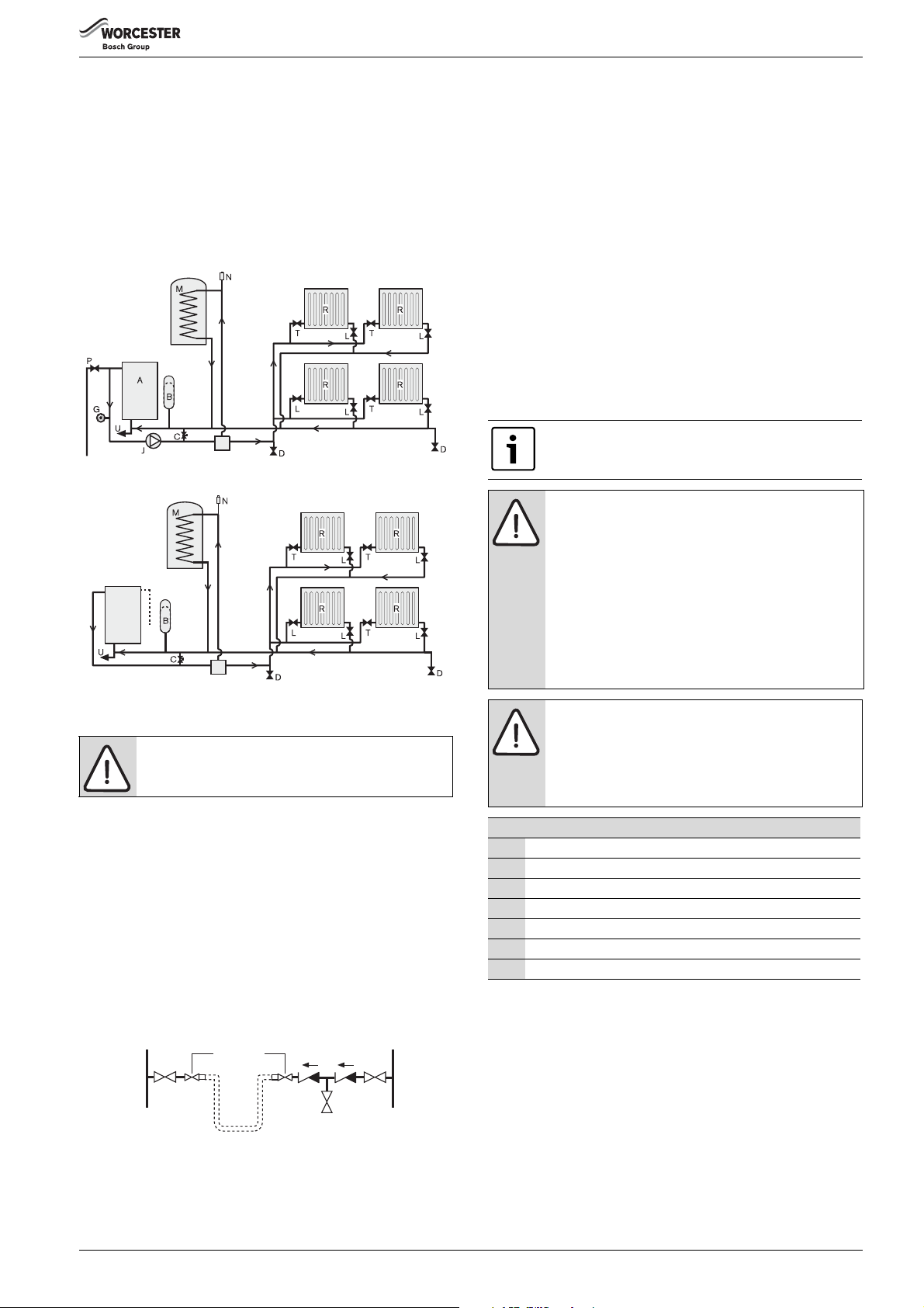
Fully pumped sealed primary system:
• A pressure relief valve (P), spring loaded safety valve set to operate
at 3bar, must be fitted to the heating flow pipe as close as possible to
the boiler or onto one of the boiler top 1” BSP outlets.
• An expansion vessel (B) must be fitted to the heating return pipe as
close as possible to the boiler and pressurised for the system volume
according to the instructions supplied with the vessel.
• A pressure gauge (G), 3 bar minimum, must be fitted to the heating
flow pipe or one of the boiler 1” BSP outlets.
• An automatic air vent (N) must be fitted.
K1
6720808218-08.1Wo
Fig. 12 Regular boiler, system layout
Fig. 13 System boiler system layout
Filling primary sealed systems
NOTICE: FILLING THE SYSTEM
▶ The system must not be filled with salt based
softened water.
• Where the system volume is more than 180 litres at 0.5 bar or
exceeds 2.65 bar at maximum heating temperature an extra
expansion vessel (B) must be fitted as close as possible to the
appliance in the central heating return.
• Pressurise the extra expansion vessel (B) to the same figure as the
expansion vessel built into the appliance (system boilers).
• Filling the system must comply with one of the methods shown in the
figure below.
• The filling point must be at low level and must never be a permanent
connection to the mains water supply.
• Filling loops must be WRAS approved.
4.5 Condensate discharge
For correct installation and trouble free operation of the appliance the
following advice should be followed:
1. All condensate pipework must ‘fall’ from the appliance by a minimum
of 3 degrees (52mm per metre) to ensure adequate condensate
flow.
2. The pipework route must allow air to be supplied back to the
appliance for correct operation of the condensate trap.
3. Connection to a rainwater down pipe must include an air break.
Also:
• Keep external pipework as short as possible and not exceed 3 metres
length.
• External pipework should be increased to a minimum diameter of
32mm and ideally be insulated.
• Minimise the number of bends and connectors.
• Remove burrs after cutting pipe.
• Remove surplus solvent from the interior of the pipe.
4.5.1 Condensate pipe work
Follow HHIC guidance and recommendations for
condensate disposal
NOTICE:
▶ Where a new or replacement boiler is being installed,
access to an internal “gravity discharge” point should
be one of the factors considered in determining
boiler location.
▶ The condensate pipe must be nominally
21.5mm Ø plastic pipe.
▶ The condensate pipe work must fall at least 52mm
per metre towards the outlet and should take the
shortest practicable route.
▶ Ensure there are no blockages in the pipe run.
NOTICE: Unheated internal areas.
The condensate discharge may freeze in areas during
prolonged cold temperatures.
▶ Internal pipe runs in unheated areas such as lofts,
basements and garages should be treated as external
runs.
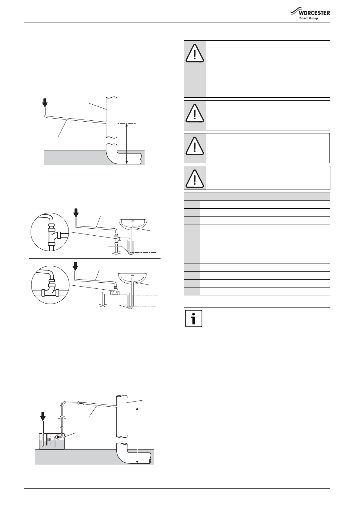
Key to condensate illustrations, figures 12, 13, 14 & 15
1 Condensate discharge from boiler
2 Soil and vent stack
3 Minimum 450mm and up to three storeys
4 Visible air break at plug hole
5 Sink or basin with integrated overflow
6 75mm sink waste trap
7 Condensate pump
Table 5 Key to Internal condensate disposal methods
Fig. 14
[SV] Stop valve
[CV] Check valve
Greenstar Danesmoor Utility
ErP+
and Utility System
ErP+
- 6 720 821 720 (2018/04) 15
Pre-Installation
6720644744-06.4Wo
21.5mm Ø
1
3
2
4.5.2 Internal connections
In order to minimise risk of freezing during prolonged cold spells, the
following methods of installing condensate drainage pipe should be
adopted, in order of priority.
Wherever possible, the condensate drainage pipe should be routed and
terminated so that the condensate drains away from the boiler under
gravity to a suitable internal foul water discharge point such as an
internal soil and vent stack. A suitable permanent connection to the foul
waste pipe should be used.
Fig. 15 Disposal to soil vent stack
Alternatively if the first option is not possible an internal kitchen,
bathroom or washing machine waste pipe etc. can be used.
Ensure that the condensate drain pipe is connected “down stream” of
the waste trap.
1
21.5mm Ø
6
1
21.5mm Ø
6
Fig. 16 Disposal to a waste pipe
CONDENSATE PUMP
Where “gravity discharge” to an internal termination is not physically
possible, or where very long internal runs would be required to reach a
suitable discharge point, condensate should be removed using a
proprietary condensate pump, of a specification recommended by the
boiler or condensate pump manufacturer.
The pump outlet pipe should discharge to a suitable internal foul water
discharge point such as an internal soil and vent stack or if not possible
to internal kitchen, bathroom or washing machine waste pipe etc. A
suitable permanent connection to the foul waste pipe should be used.
1
21.5mm Ø
7
Fig. 17 Condensate pump disposal
75mm
min.
75mm
min.
2
3
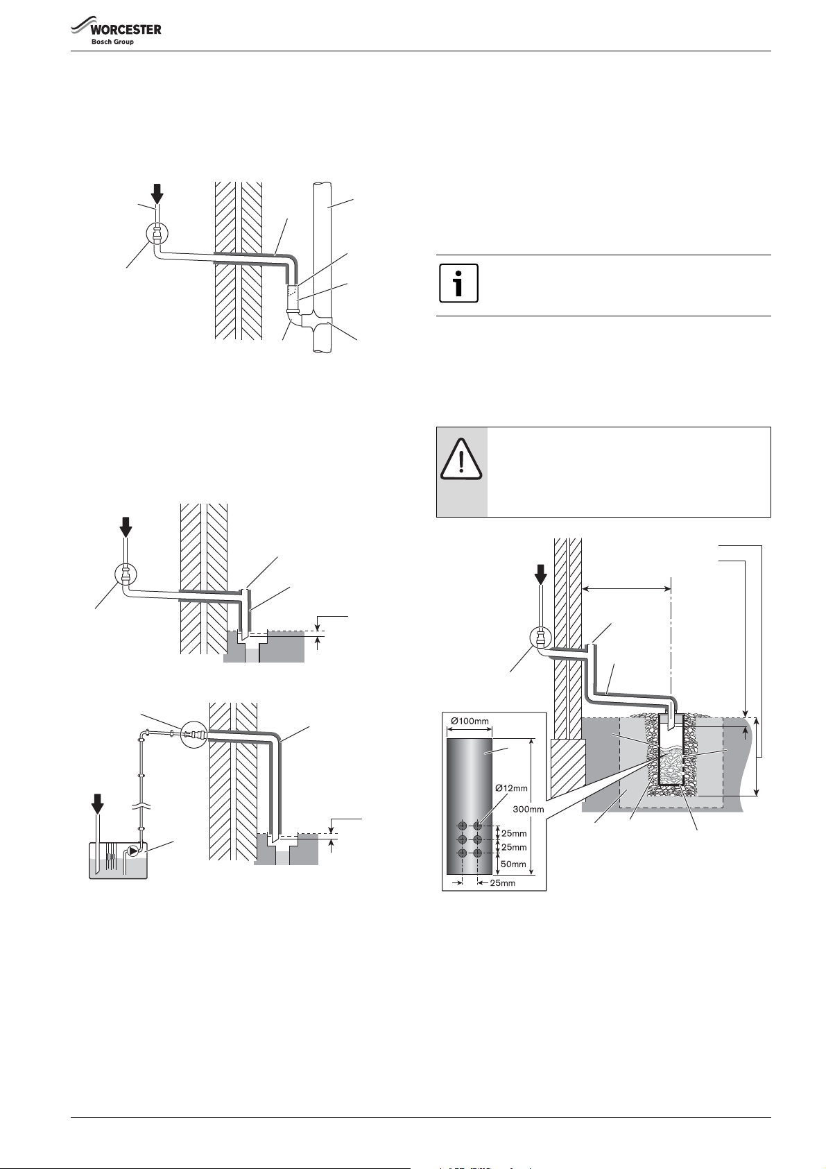
4.5.3 External connections
NOTICE: Rainwater or external drain disposal
Untreated condensate must not be allowed to flow into
streams or rivers
▶ A rainwater down pipe or an external drain shall only
be used for condensate disposal if the down pipe or
external drain is connected to a combined foul and
rainwater system
▶ Refer to BS 6798 for more information
NOTICE: Grey water systems
Contamination of recovered water
▶ Condensate disposal shall not be allowed into a grey
water recovery system that is intended for re-use
NOTICE: Freezing conditions
▶ Pipe work length should be kept to a minimum and the
route as vertical as possible.
▶ When required, use only weather proof insulation.
NOTICE: Condensate waste
▶ Care should be taken when siting a soak-away to
avoid obstructing existing services.
Continued - Key to condensate illustrations, figures 13,14, 15 & 16
8 Pipe work transition
9 Insulate and increase pipe size
10 External rain water pipe into foul water
5
11 External air break
12 Air gap
13 PVCu strap-on fitting
14 43mm 90 male/female bend
15 100mm Ø minimum plastic pipe
16 Drainage holes
17 Limestone chippings
5
18 Bottom of sealed tube
19 Increase size of soak-away with lime chippings if in clay soil
Table 6 Key to external condensate disposal methods
6720819188-03.3Wo
Condensate drainage pipe can be run above or below
ground. If the pipe work is run under ground, care must
be taken to ensure that the pipe work “fall” towards the
disposal point is maintained
If no other discharge method is possible then the use of an externally run
condensate drainage pipe terminating at a suitable foul water discharge
point, or purpose-built soak away, may be considered. If this method is
chosen then the following measures should be adopted:
▶ The external run be kept as short as possible and not exceed 3
metres.
▶ The pipe should be run internally as far as possible before going
externally and the pipe diameter should be increased to 32mm
before it passes through the wall to the exterior. The pipe should be
insulated using suitable waterproof and weather resistant insulation,
if not using a CondenseSure siphon.
▶ The external pipe should take the shortest and least exposed route to
the discharge point, and should "fall" as steeply as possible away
from the boiler, with no horizontal runs in which condensate might
stand.
▶ The use of fittings, elbows etc. should be kept to a minimum and any
internal “burrs” on cut pipe work should be removed so that the
internal pipe section is as smooth as possible.
6720819188-12.2Wo
Greenstar Danesmoor Utility
ErP+
and Utility System
ErP+
- 6 720 821 720 (2018/04)16
Pre-Installation
6720810188-05.5
21.5mm Ø
9
10
11
12
13
14
8
1
6720644744-10.4Wo
9
25mm min.
1
11
8
6720644744-12.4Wo
9
25mm min.
8
1
7
6720821683-30.1Wo
500mm min.
25mm min.
400mm min.
9
16
18
17
19
15
15
16
1
8
11
Unsuitable for clay soil types
FITTING AN EXTERNAL AIR BREAK
• Refer to figure 18 when a rain water down pipe is used to dispose of
condensate.
• An air break must be installed in the 43mm pipe work, between the
boiler condensate outlet and the drainpipe, outside the property, to
avoid flooding during adverse weather conditions.
Fig. 18 Disposal into a rainwater down pipe
Where the pipe terminates over an open drain or gully, the pipe should
terminate below the grating level, but above water level, in order to
minimise “wind chill” at the open end.
The use of a drain cover (such as those used to prevent blockage by
leaves) may offer further protection from wind chill.
Pipe drainage will be improved if the end is cut at 45° as opposed to a
straight cut.
CONDENSATE SOAK AWAY
• The condensate soak away must be sited at least 500mm away from
building footings.
• The condensate drainage pipe may be run above or below the ground
to the soak away. The examples shown on this page run above
ground.
• The soak away must use a 100mm Ø plastic tube with two rows of
three 12mm holes on 25mm centres and 50mm from the bottom of
the tube. The holes must face away from the house.
• The tube must be surrounded by at least 100mm of limestone
chippings to a depth of 400mm.
Minimum hole size for the condensate soak away must be
400mm deep by 300mmØ .
In situations where there are likely to be extremes of temperature or
exposure, the use of a proprietary trace-heating system for external pipe
work, incorporating an external frost thermostat, should be considered.
If such a system is used, the requirement to use 32mm pipe does not
apply. However, all other guidance above and the instructions for the
trace heating system, should be closely followed.
NOTICE: Unheated internal areas.
▶ Internal pipe runs in unheated areas such as lofts,
basements and garages should be treated as external
runs and consideration should be given to using a
CondenseSure siphon.
Fig. 19 External disposal
Fig. 20 Condensate pump to external disposal
Greenstar Danesmoor Utility
ErP+
and Utility System
Fig. 21 To a soakaway
ErP+
- 6 720 821 720 (2018/04) 17
Pre-Installation
1
2
3
4
2
3
4
1
2
6720646608-123.1Wo
4.6 Pressure relief pipework
• The pressure relief discharge pipe (1) should be at least 15 mm
diameter copper pipe and run downwards away from the boiler and
discharge away from any electrical or other hazard, preferably to an
external drain or soakaway.
• Pipe (3) should be finished with a partial bend, near the outlet to face
the external wall (as shown) to help prevent freezing.
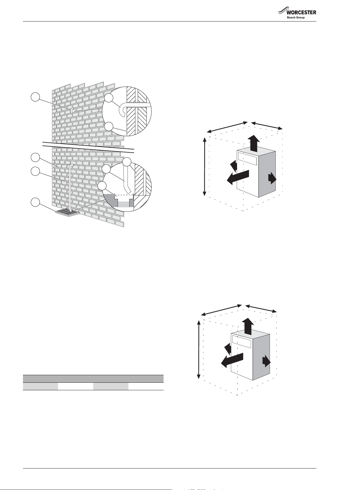
Room sealed balanced flue models (RS)
The appliance does not require a separate vent for combustion air.
Installation in cupboards or compartments require permanent vents for
cooling purposes, one at high level and one at low level, either direct to
outside air or to a room.
Both vents must pass to the same room or be on the same wall to the
outside air.
The minimum air vent free area is given in the table opposite.
Installation clearances
Figure 23 shows the minimum space recommended to install the boiler
only.
1200mm
570mm
300mm
100mm
1155mm
100mm
600mm
6720808218-16.1Wo
Fig. 23 Installation clearances
Fig. 22 Pressure relief pipe work
[2] Outside wall
[1, 3] PRV discharge pipe
[4] External drain
Service clearances
Figure 24shows the minimum space required to carry out an annual
service.
* Remove the flue 'knock-out' panel sections if this clearance is less than
75mm.
4.7 Boiler locations and clearances
This boiler is only suitable for installing internally within a property at a
suitable location onto a fixed rigid surface of the same size as the boiler
and capable of supporting the boiler weight.
The boiler must be installed on a flat level surface to ensure condensate
The appliance is suitable for an under worktop installation providing that
the worktop above the boiler (min 10mm clearance) is removable for
maintenance and repair and the front of the boiler is not enclosed.
** Due to changes to BS 5410 and modern building design, these figures
no longer incorporate the adventitious ventilation allowance.
does not enter the primary heat exchanger.
The boiler is not suitable for external installation unless a suitable
enclosure is provided.
1200mm
380mm
10 m m
Roof space installations must fully conform to BS 5410 part 1 section
4.6.9.
Open flue model (CF)
In order to ensure clean and efficient combustion an adequate supply of
air must be delivered to the combustion chamber.
To provide sufficient air a suitable inlet must be provided into the room
or space in which the boiler is situated.
5mm*
865mm
5mm*
600mm
Output 12/18 18/25 25/32
2
Size cm
An air brick or other form of continuous air supply may have to be built
into the installation in order to ensure an adequate supply of air.
99 138 165
6720808218-17.1Wo
Fig. 24 Service clearances
If the appliance is to be installed in a confined space or compartment two
air vents are required, one at high level and one at low level.
The minimum free area of each vent is shown opposite and depends
whether the air is taken from another room or from outside the building.
Where the air is taken from another room that room must contain an air
inlet as described above.
Greenstar Danesmoor Utility
ErP+
and Utility System
ErP+
- 6 720 821 720 (2018/04)18
 Loading...