

Bosch Worcester 240 Combi OF Installation And Servicing Instructions
....--~~~ORCESTER-----.
BOSCH
240
WALL
MOUNTED
COMBINATION
MAINS
Combi OF
FED
INSTALLATION AND
SERVICING
BOILER
DOMESTIC
FOR
HOT
CENTRAL
WATER
HEATING
AND
INSTRUCTIONS
IMPORTANT:
THESE
INSTRUCTIONS
To
THIS
THESE
GC
NUMBER
BOILER
Automatic Modulating Control
Domestic
Maximum 24.0 kW (82,000 Btu/
APPUANCE
INSTRUCTIONS
ARE
Hot
Minimum
TO
BE
LEFT
47
311
OUTPUT
Water and Central Heating
9.2 kW
(31
,400
IS
FOR
USE
APPLY
WITH
IN
THE
09
Btu/h)
WITH
THE
USER
h)
NATURAL
UK
ONLY
OR
AT
GAS
THE
ONLY
GAS
METER
Contents
1. Installation Requirements
2.
3.
4.
5.
6.
7.
8.
9.
General
Technical
Siting
Siting
Air
Sealed
Open
Domestic
Information
Data
the Appliance
the
Flue
Supply
....
System
Vent Primary
Hot
...................
Terminal
...................................................................
..........................................................
Water
....
.....
....................................
.......
........
...
..................................
......
...........
.....
..................
......................................................
..........................
Water
System
......
...............
.......................................
1. Installation Regulations
1.1
Gas
Safety (Installation and
All
gas appliances must
accordance
with
the above regulations.
ances correctly could lead to prosecution.
The
1.2
overrid
1.3
fer
of
ments
amended, current
tions,
the
Electridty
(
the
BS
b
BS
BS
tic
BS
in
BS
input not exceeding
BS
t
ions
1
standards, t
other relevant
manufacturers notes must not
ing
statutory obligations.
The
compliance
immunity
this
appliance must
of
the
Building
local
relevant
6798:1987
oilers
of
5449
:19
Water
at
rated input not exceeding 60
90
with a British
from
legal
be
Gas
Safety
(Install
lEE
Wiring
Standards (
Company. Health
Work
Regulat
recommendations
Specifi
cati
Central Heating
5546:1990 Installation of gas hot water supplies
purposes.
5440:1:1990
put not exceedi
Flues
ng
60
and
kW:
5440:2:1989 Flues and
60kW: Air
6891
:1988 Installation
up
to
28
mm
(R
1 ).
.4
To
ensure that the installation
he
system and components should conform to any
Br
itish Standards
in the instructions.
Use)
Regulations 1984
be
installed
by
a competent person
Failure
be
Standard does
obligations.
in
accordance
In
particular the installation
with
ati
on
and
Use)
Regulations,
local
ScotlandXConsolidation)
and Safety Document No. 635
ions
).
!t
should
be
of
the f
ollowing British
on
for
installati
on
of gas
kW.
for Domestic Premises.
Ven
tilati
on
for
gas appliances
Flues
.
Ventilation
for
gas appliances
Supply.
of low
pressure gas pipework installa·
will
perform to the highest
in
addition
..
.....
.............
.........
......
.........
...............
to
install appli·
taken,in any
not.
of
itself.
the
relevant
Regulations
Building
and
byelaws
in
accordance w
Standards.
fired
hot water
for
to
those mentioned
Page
2
Page
2
Page
4
Page
5
Page
6
Page
6
Page
7
Page
8
Page
8
way
,as
con
require
1984 as
Regula·
ith
domes·
of
rated
of
rated
in
of
10.
Electrical
11
. Installation
12. Commissioning ...........................................
13.
Instructions
14
. Inspection and Servidng
15
. Replacement
16
. Short Parts List
17
. Operational
18.
Fault
An
optional
Operating
2.5 ELECTRICAL SUPPlY
Mains supply:
Internal fuses:
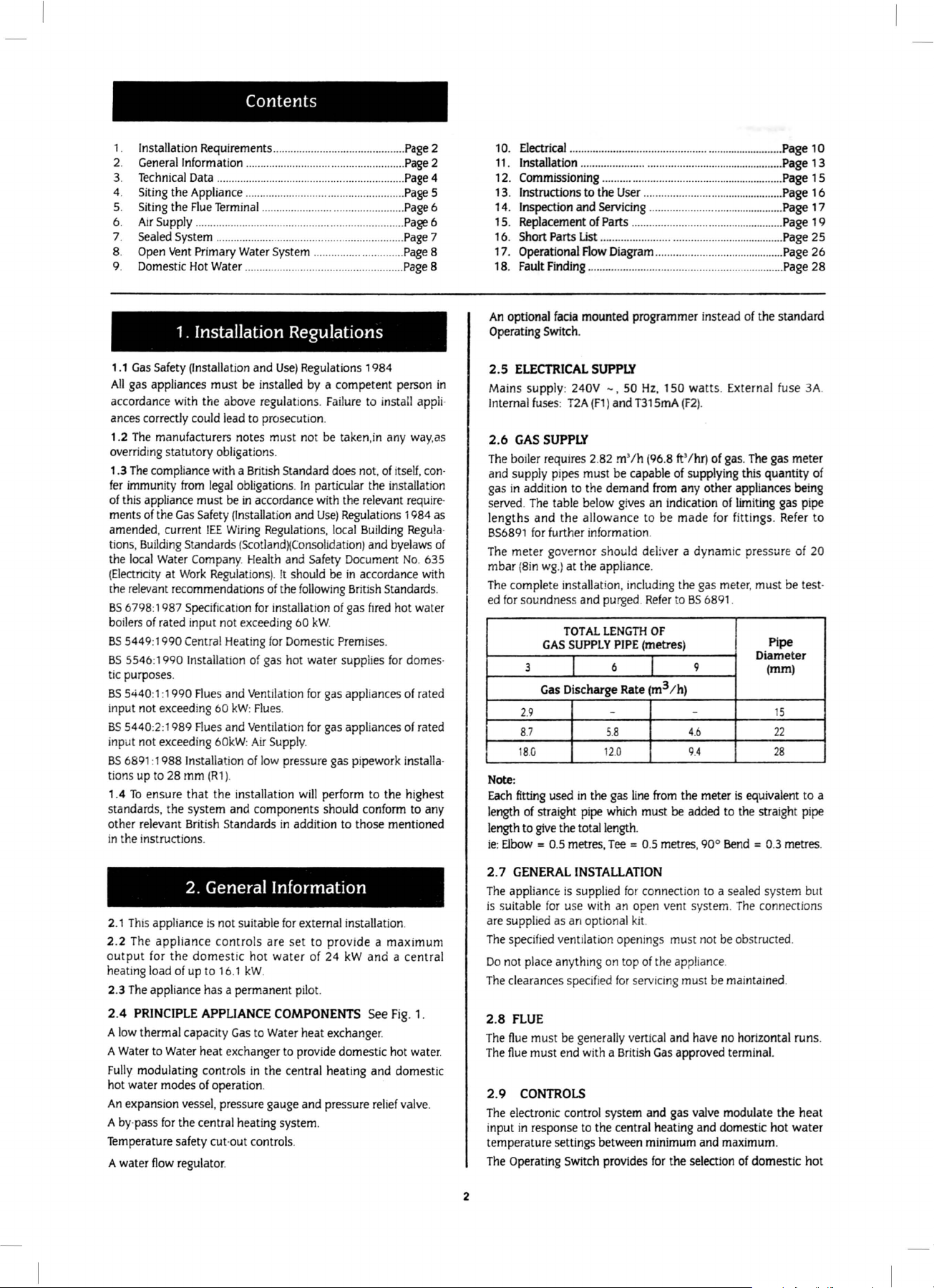
2.6
GAS
The
·
boiler requires 2.
and supply pipes must be capable
gas in addition
·
served.
lengths and the allowance to be made for fittings.
BS6891 for
The
meter
mbar (B
The
complete installation,
ed
for
soundness and purged.
3
2.9
8.7
18.G 12.0 9.4
Note:
Each
fitting
length
of
length to
ie: Elbow
.................
Finding ....................
facia
Switch
240V
T2A
SUPPLY
to
The
table below gi
...
.......
................
to
the
of
Parts
...
...............
Flow
Diagram ...
.................
....
...................
User
...........................................
..........
...........
....
.....
.....................
................
..........................
...........................
..........................
...................
..........................................
mounted programmer instead
.
-,
50
Hz,
150 watts. External fuse
(F1)
and
T315mA (F2).
82
m'
/h (96.8
the demand
ves
ft
' /hr)
of
supplying this quantity
from any other appliances being
an ind
icati
on
further information.
gov
ernor should deliver a dynamic pressure
in wg.)
at the appliance.
TOTAL
GAS
SUPPLY
Gas
Discharge Rate
used in the gas
straight p
give
= 0.5 metres,
ipe
the total
including
LENGTH
PIPE
6 9
- -
5.8
line
which
length
Tee
= 0.5 metres,
the gas meter, must
Refer
to
BS
OF
(metres)
(m3
/h)
4.6
from
the meter
must be
added
.
6891
90° Bend
........
...................
..............
.........
...
...................
of
of
gas.
of
limiting
.
is
equivalent to a
to
the straight
........
Page 10
......
Page 1 3
Page 1 5
...
..
Page 16
........
.. Page 17
Page 19
..... Page 25
Page 26
Page
the standard
The
gas meter
gas pipe
Refer
of
be
test·
Pipe
Diamet
er
(mm)
15
22
28
pipe
= 0.3 metres.
28
3A.
of
to
20
2. General Information
2.1
This
appliance is
The
2.2
output
heating load
2.3
2.4
A
A
Fully
ho
An
A
appliance controls are set to provide a maximum
for
the domestic hot water
of
The
appliance has a permanent
PRINCIPLE APPLIANCE COMPONENTS See
low
thermal capacity
Water
to
Water
modulating controls
t water modes
expansion vessel, pressure gauge and pressure
by
·pass
for
Temperature safety
A water
flow
not
suitable
up
to 16.1 kW.
Gas
heat exchanger
in
of
operation.
the central heati
cut·out controls.
regulator.
for
external installation.
of
pilot.
to
Water
heat exchanger.
to
provide domest
the central heating and domes
ng
system.
24
kW
and a central
Fig
. 1.
ic
hot
water.
tic
relief
valve
.
2. 7 GENERAL INSTALLATION
The
appliance:
is
suitable
are suppl
The
spec
Do
not
The
clearances specified
2.8
FLUE
The
flue must
The
flue
2.9 CONTROLS
T
he
electronic control system and gas
in
input
is
supplied
for
use
with
an
ied
as an option
ified
ventilation openings must
pla
ce anything
al
on
for
be
generally
must end
response to t
with a British
he
central heati
for
connec
open vent system.
kit.
top
of
the appliance.
servici
verti
cal
Gas
temperature settings between minimum and
The
Operating
2
Switch
provides
for
tion
to a sea
led
The
not
be obst
ng
must
be
maintai
and have
approved
the selecti
no
horizontal runs.
terminal.
valve
modulate the heat
ng
and domestic hot water
max
imum.
on
of
domestic hot
system but
connections
ructed.
ned
.
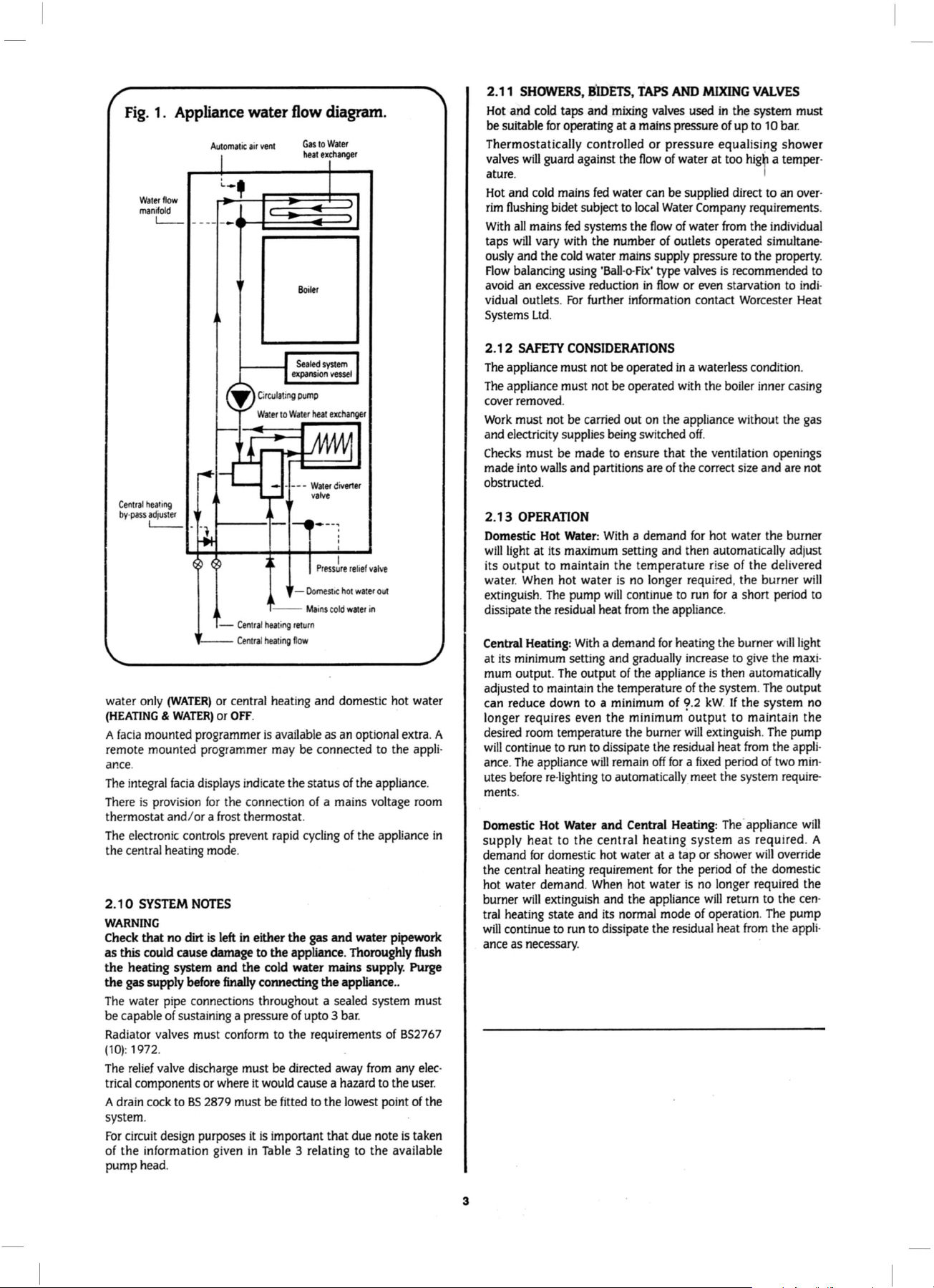
Fig.
1. Appliance
Waterflow
manifold
L_
Central hearing
by
·
pass adj
uster
t__
- -
..
--
water
only
(WATER)
(HEATING & WATER)
A
fac
ia mounted programmer
remote mounted
prog
Automat
-
water
ic
Central heati
Cen
flow diagram.
air
vent
- ----
---,--
-Oomestoe
-ng
retu
tral heati
ng
flow
Gas
heat
Boile
Mains
rn
to
Water
exchanger
r
Water
v
alve
-:
Pr
essure
cold water
div
erter
I
I
reli
ef val
ve
hot
wate
r out
in
or central heating and domestic hot water
or
OFF
.
is
ava
ilable as an optional extra. A
rammer may be connected
to
ance.
The
integral
fac
ia displays indicate the status
prov
ision
for
There is
thermostat and/ or a
The
electronic controls prevent rapid
the connection
frost
thermostat.
of
the appliance.
of
a mains voltage
cycling
of
the appliance
the central heating mode.
2.1
0
SYSTEM
NOTES
WARNING
Check that no dirt is left
as
this could cause
the heating system and the cold water
the gas supply before
The
water pipe connections throughout a sealed system must
be capable
of
sustaining a pressure
Radiator valves must conform
(10): 1972
The
relief
.
valve
discharge must be directed
trical components or where
A drain
cock
to
BS
in
either the
damage
finally
it
2879 must
gas
and water pipework
to the appliance. Thoroughly flush
mains supply. Purge
connecting the appliance
of
upto 3 bar.
to
the requirements
away
from
would
cause a hazard to the
be
fitted
to
the lowest point
system.
For
circu
it design purposes
of the informati
on given
it
is
important that due note
in
Table
3 relating
to
the available
pump head.
the appli-
room
..
of
BS2767
any
elec
user.
of
is
taken
the
in
2.11
Hot
be
suitable
SHOWERS,
and
cold
BIDETS,
taps and
for
operating at a mains pressure of up
TAPS
mixing
AND
MIXING
valves used
VALVES
in
the system must
to
1 0 bar.
Thermostatically controlled or pressure equalising shower
valves
will guard against the
ature.
Hot
and
cold
mains
fed
rim
flushing
With
taps
ously and the
Flow
avoid
vidual outlets.
Systems
2.12
The
appliance must not be operated
The
appliance must not be operated wi
bidet subject
all
mains
fed
systems the
will vary with the number
cold
water mai
balancing
using
an excessive reduction
For
further information contact Worcester Heat
Ltd
.
SAFETY
CONSIDERATIONS
flow
of
water at too
higb
water can be supplied direct to an
to
local
Water
Company requirements.
flow
ns
'Ball-o-Fix'
in
of water
of
outlets operated simultane-
supply pressure
type valves
flow
in
from
the individual
to
the property.
is
recommended
or
even
starvation
a waterless condit
th
the boiler inner casing
a temper-
I
to
ion
over-
to
indi
.
-
cover removed.
Work
must not
and electricity supplies
Checks
made into
be
carried out
must be made
walls
and partitions
on
the appliance without the gas
being
switched
to
ensure that the ventilation openings
off
.
are
of
the correct size and
are
not
obstructed.
2.13
OPERATION
Domestic Hot Water:
will
light
at its maximum setting and then automatically adjust
With
a demand
for
hot water the burner
its output to maintain the temperature rise of the delivered
water.
When
hot water
extinguish.
The
pump
dissipate the residual heat
Central Heating:
at its
mum
minimum
output.
setting and gradually increase
The
adjusted to maintain the temperature
can reduce down to a minimum of
With
output
is
no
will
continue
from
a demand
of
the appliance
longer required, the burner
to
run
for
a short period
the appliance.
for
heating the burner
to
is
then automatically
of
the system.
?.2
kW.
If
will
give
the
The
output
the system
will
light
maxi
to
-
no
longer requires even the minimum output to maintain the
room
desired
will
continue
ance.
The
utes
before re-lighting
temperature the burner
to
run
to
dissipate the residual heat
appliance
will
remain
to
automatically meet the system
off
for a fixed
will
extinguish.
from
period
The
of
the
two
require-
pump
appli
min
-
-
ments.
Domestic Hot Water
supply
demand
heat
for
domestic hot water at a tap or shower
the central heating requirement
hot water demand.
burner
will
extinguish and the appliance
tral heating state and its normal mode
will
continue
ance
as
necessary.
to
and
Central Heating:
The
· appliance
will
to the central heating system as required. A
will
override
for
the period
When
hot water
is
run to dissipate the residual heat
of
the domestic
no
longer required the
will
return to the
of
operation.
The
from
cen
pump
the appli·
-
-
3
TABLE
The
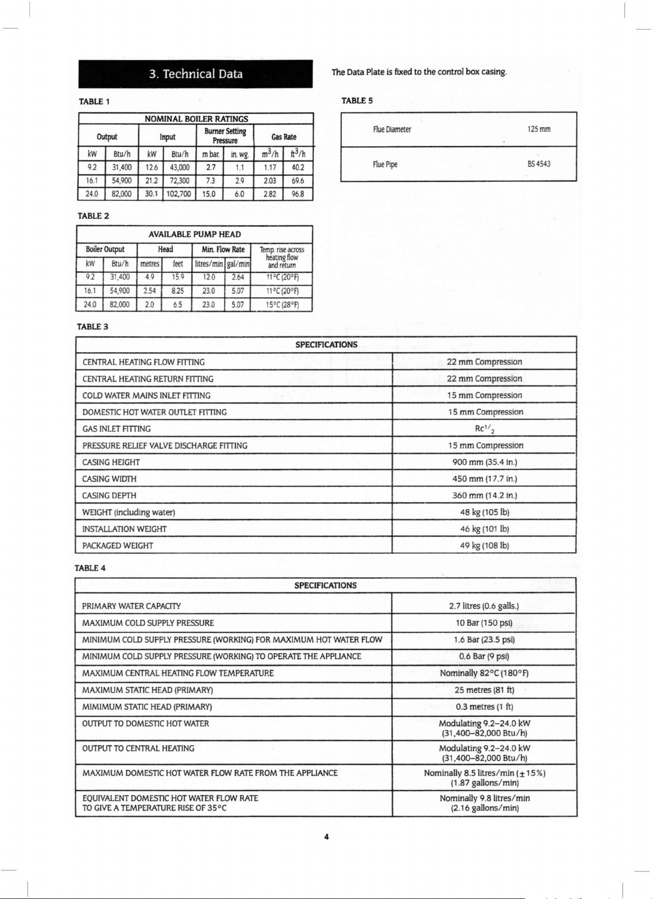
3. Technical Data
1
Data Plate is
TABLE
fixed
to
the control box casing.
5
OUtput
kW
9.2 31,
16
.1
24
.0
TABLE2
Boiler
Output
kW
9.2 31,
16
.1 54,9
24
.0
TABLE
3
CENTRAL
CENTRAL
COLD
WATER
DOMESTIC
GAS
INLET
PRESSURE
CASING
CASING
CASING
WEIGHT
INSTALLATI
PACKAGED
NOMINAL
Btu/h
54,900
82,000
Btu
82,000
HEIGHT
WIDTH
DEPTH
(including water) 48
kW
400 12.6
212
30
AVAILABLE PUMP HEAD
/h
metres
400
4.9
00 2.54
2.0 6.5
HEATING
HEATING
MAINS
HOT
WATER
FrrnNG
RELIEF
VALVE
ON WEIGHT
WEIGHT
.1
FLOW
RETURN
Input
Btu
/h
43,000
72,300
102,700
Head
feet
15
Q
8.
25
FriTING
INLET
FrrnNG
OUTLET
DISCHARGE
BOILER
RATINGS
Burner
Setting
Pressure
mbar. in.wg. m3/h
2.7
1.1
73
2.9 2.
.0
Flow
FriTING
6.0
Rate
gal/min
2.
64
15
Min.
litres/min
120
23.0 5.07
23.0 5.07
FmiNG
FmiNG
Gas
1.17
03
2.
82
Temp
heating
and
11
11
•c
15
Rate
3
/h
tt
40.2
69
.6
96
.8
.
rise
across
flow
return
•c
(
20"FJ
(20"FJ
°C {28
°F)
SPECIFICATIONS
Flue Diameter
Flue
Pipe
22
22
15
15
15
900
450
360
mm
Compression
mm
Compression
mm
Compression
mm
Compression
Rc
mm
Compression
mm
mm
mm
kg
(10Sib)
46
kg
(101
49
kg
(1
1'2
(35.4 in.)
(17
.7 in.)
(14.2 in.)
lb)
08 lb)
125mm
BS
4543
TABLE4
PRIMARY
MAXIMUM
MINIMUM
MINIMUM
MAXIMUM
MAXIMUM
MIMIMUM
OUTPUT
OUTPUT
MAXIMUM
EQUIVALENT
TO
WATER
COLD
COLD
COLD
CENTRAL
STATIC
STATIC
TO
DOMESTIC
TO
CENTRAL
DOMESTIC
GIVE A TEMPERATURE
DOMESTIC
CAPACITY
SUPPLY
SUPPLY
PRESSURE
SUPPLY
PRESSURE
HEATING
HEAD
(PRIMARY)
HEAD
(PRIMARY)
HOT
HEATING
HOT
HOT
PRESSURE
(WORKING)
(WORKING)
FLOW
WATER
WATER
FLOW
WATER FLOW
RISE
OF
35°C (2.16 gallons
FOR
TO
OPERATE
TEMPERATURE
RATE
FROM
RATE
SPECIFICATIONS
MAXIMUM
THE
THE
APPLIANCE
HOT
WATER
APPLIANCE
4
FLOW
2. 7 litres (0.6 galls.)
1 0 Bar
(1
50 psi)
1.6 Bar (23.5 psi)
0.6 Bar
(9
Nominally 82°C (180°F)
25 metres (
0.3 metres
Modulating 9.
(31
,40Q-82,000 Btu
Modulating 9.2
(31
,400-82,000 Btu
Nominally 8.51itres
(1
.87 gallons/min)
Nominally 9.
8litres
psi)
81
(1
2-24
-24
/min
/min)
ft)
ft)
.0 kW
/h)
.0 kW
/h)
(±
/min
15%)
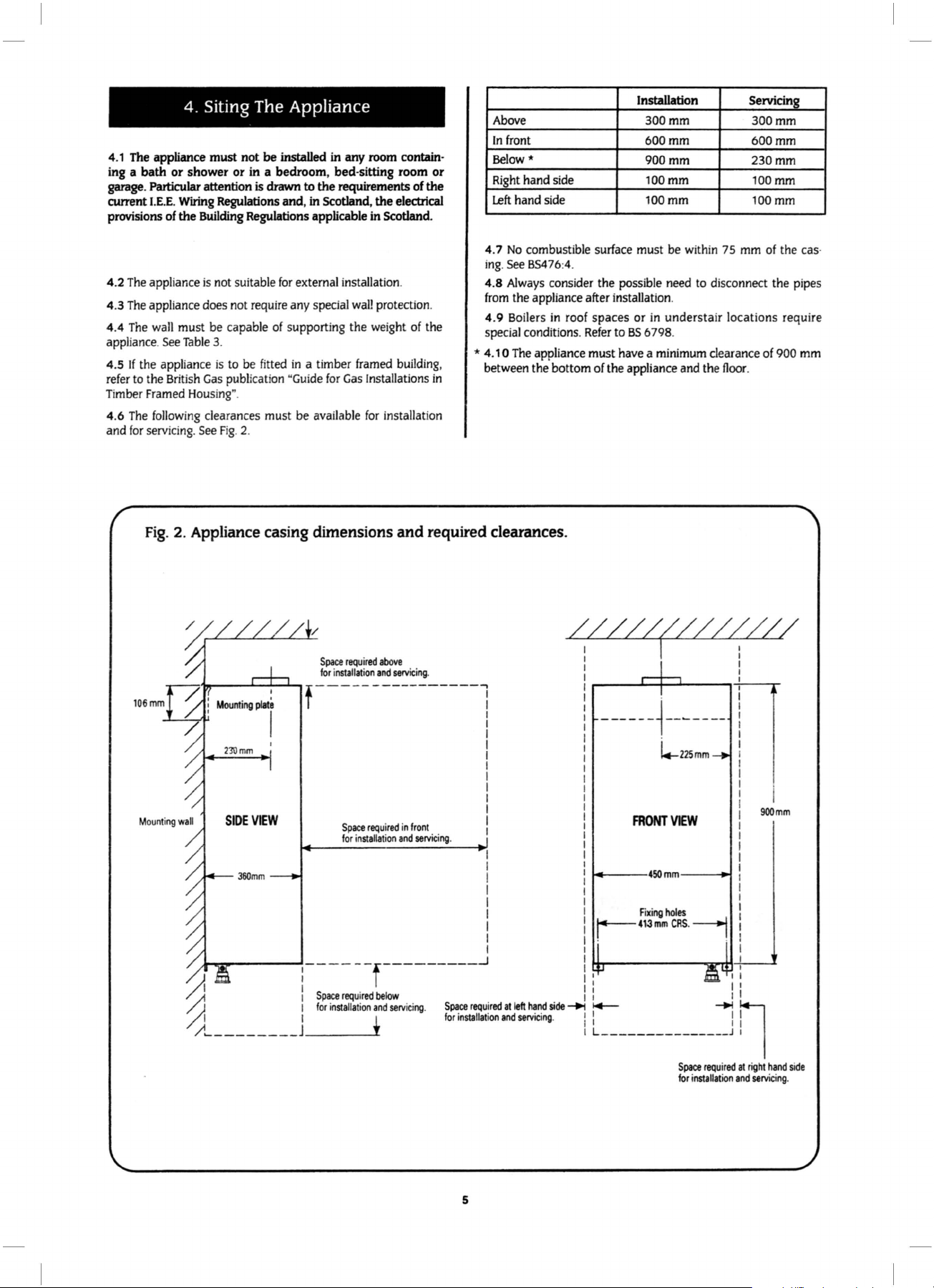
4. Siting The Appliance
4.1 The appliance
ing a
bath
garage. Particular attention is drawn to
current
I.E.E.
provisions of
The
appliance
4.2
The
appliance does not require any special
4.3
The
4.4
appliance. See
4.5
refer to the British
Timber Framed Housing".
4.6
and
wall must be capable of supporting the weight of the
If
the appliance
The
following clearances must be available
for
servicing. See Fig. 2.
must
not
be installed
or
shower
Wiring Regulations and,
the
Table
or
in a
bedroom,
Building Regulations applicable
is
not suitable
3.
is
to be fitted
Gas
publication "Guide
for
external installation.
in
in
any room contain-
bed-sitting
the
requirements of
in
Scotland,
wall
a timber framed building,
for
Gas
room
the
electrical
in
Scotland.
protection.
Installations
for
installation
or
the
in
Installation
Above
In
front
Below*
Right hand side
Left
hand side
4.7
No
combustible surface must be within 75 mm of the cas·
ing
. See BS476:4.
4.8 Always consider the possible need to disconnect the pipes
from the appliance after installation.
4.9 Boilers in roof
special conditions.
* 4.
10
The appliance must have a minimum clearance of 900 mm
between the bottom
spaces
Refer
ofthe
300mm
600mm
900mm
100mm 100mm
100mm 100mm
or
in
understair
to
BS
6798.
appliance and the floor.
Servicing
300mm
600mm
230mm
locations require
Fig.
106mm
2.
Appliance casing dimensions
Space
required
for installalion
f-----
SlOE
VIEW
Space
for installation
:----
~
/).
/)~
____
____
I
Space
required
1
for
installation
j t
and
required clearances.
above
and
servicing
.
-----------~
I
I
I
I
I
I
I
I
I
I
required
in
and
front
servicing
I
I
.
I
I
I
I
I
I
I
I
Space
,,,
...
I
_j
required
, • • M
at
left
hand
..
,......
__ f _________
below
and
serv
icing.
////~/////J/~
I I
I I
I I
I :
I
I
I
I
------~-
I
I
I
I
I
I
I
I
I
I
I
FRONT
~-----4~mm----~
~413mm
I
1 I
side
-+1
I+-
. i
L_
______________
-
~----
~225mm
VIEW
Fixing
holes
CAS.___,
~--~
I
II
-+1
j ! I
900mm
il
Space
required
at
right
hand
for
installa
tion
and
5
servicing
side
.
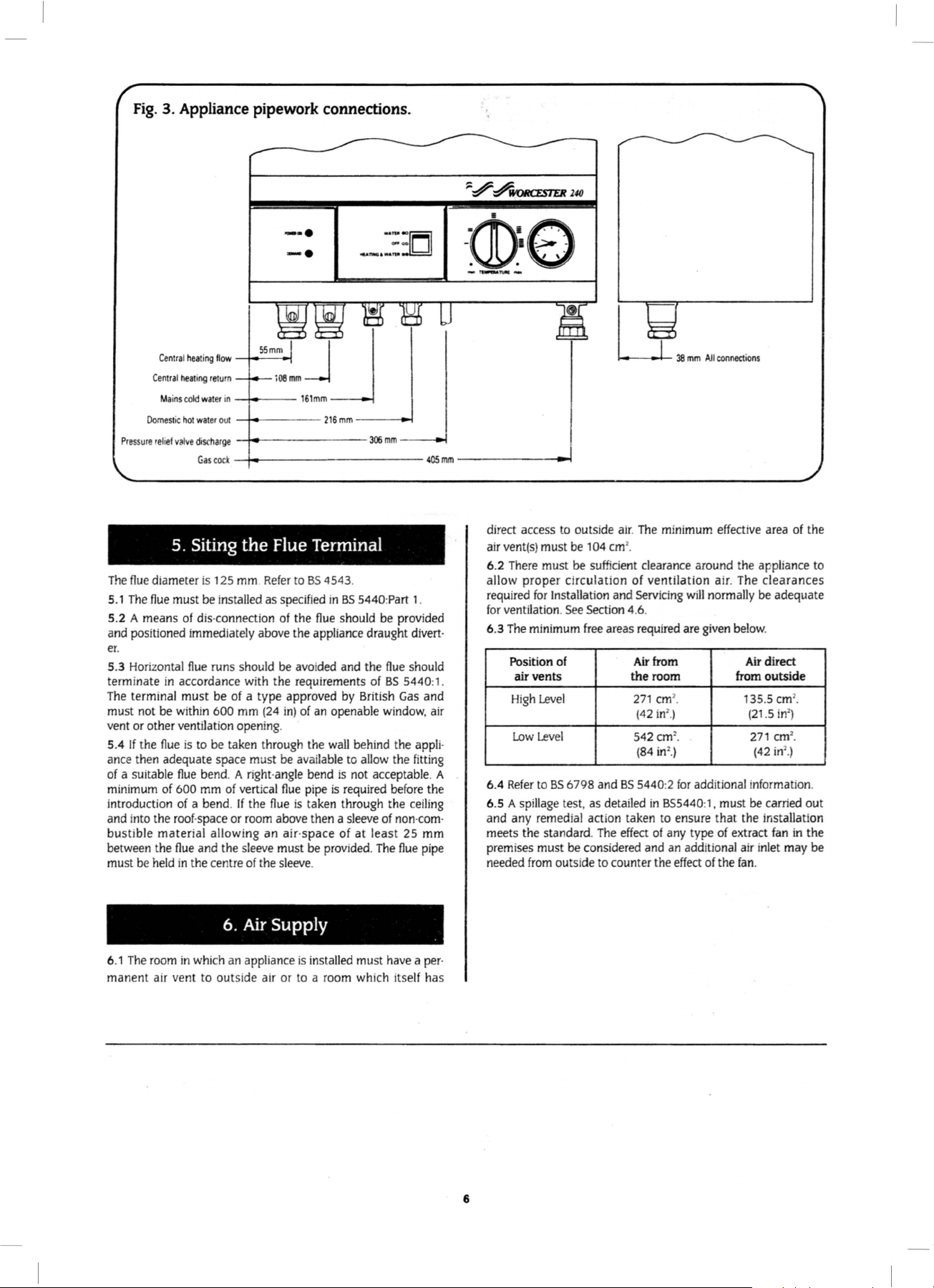
Fig.
3. Appliance pipework connections.
-·
·
-·
"'
"":
__
,_::D
rr-;J
tt\·r:!\
-w·o
_,....,..YI.III_
Central heating
Central
hearing
return
Mains
cold
water
Domest
ic
hot
water
Pressure
relief
valve
discharge
Gas
cock
5. Siting
The
flue
diameter
The
5.1
5.2 A means
and positioned immediately above the appliance draught divert·
er
5.3
terminate
The
must not be
vent
5.4
ance t
of
minimum
introduction
and i
bustible material allowing an air-space of at least 25
between the
must
flue
.
Horizontal
terminal must be
or
other ventilation opening.
If
the
hen
a suitable
nto
the
be
held
is
125
must
be
of
dis
-connection
flue
runs should be
in
accordance with the requirements
within
600
flue
is
to
be taken through the
adequate space must
flue
bend. A right·
of
600
mm
of
a bend.
roof
·space
flue
and the
in the centre
55
flow
in --114--
out
--
-1--
----
-1--
-------
-
1--
-----------
mm
the
mm
Refer
installed as
of
a type approved
mm
(24
of
verti
cal
If
the
flue
or
room
sleeve
of
the
Jj
i
08
mm
161mm
216
mm
-----<
306
Flue Terminal
to
BS
4543.
specified
of
in)
be
angle
flue
above then a
must
sleeve
in
BS
5440:
the
flue
should
avoided
available
is
and the
by British
of
an
openable
wall
behind the
to
allow
bend
is
not
pipe
is
required
taken through the
sleeve
be
provided.
.
of
acceptable. A
~
mm
--
Part
be
provided
flue
BS
5440
Gas
window.
the
before
of
non·com
The
flue
~
405mm
1.
should
:1.
and
air
appli·
fitting
the
ceiling
mm
pipe
------
·
-~
direct access
air
vent(s)
6.2
There
allow proper circulation
required
for
ventilation.
6.3
The
Position
air vents the room
High
Low
6.4
Refer
6.5 A
and any remedial acti
meets the standard.
premises must
needed
must
must
for
Installat
minimum
Level
Level
to
BS
spillage
from
to
outside air.
be
104
cm
be
sufficient
ion
and
See
Section
free
areas
of
6798 and
test, as detailed
on
The
be
considered and
outside
to
counter the
The
minimum
2
.
clearance around the appliance
of
ventilation air.
Servicing
4.6.
required
Air
from
2
271
cm
2
(42
in
.)
2
542
cm
2
(
84
in
.)
BS
5440:2
in
855440:1, must
taken
to
effect
of
any
an
effect
effective
The
will
normally
are g
iven
below
Air direct
from
of
of
extract
the
fan
135
(21
271
(42
be
.
•
•
for
additional information.
ensure that the installation
type
additional air
area
of the
clearances
be
adequate
.
outside
2
.5
cm
.
2
.5 in
)
2
cm
•
2
in
.)
carried out
fan
in the
inlet
may be
to
6.1
The
manent
room
air
in
vent
6.
which
an
to
outside air or
Air
Supply
appliance
is
installed must
to a room
have a per
which itse
·
lf has
6
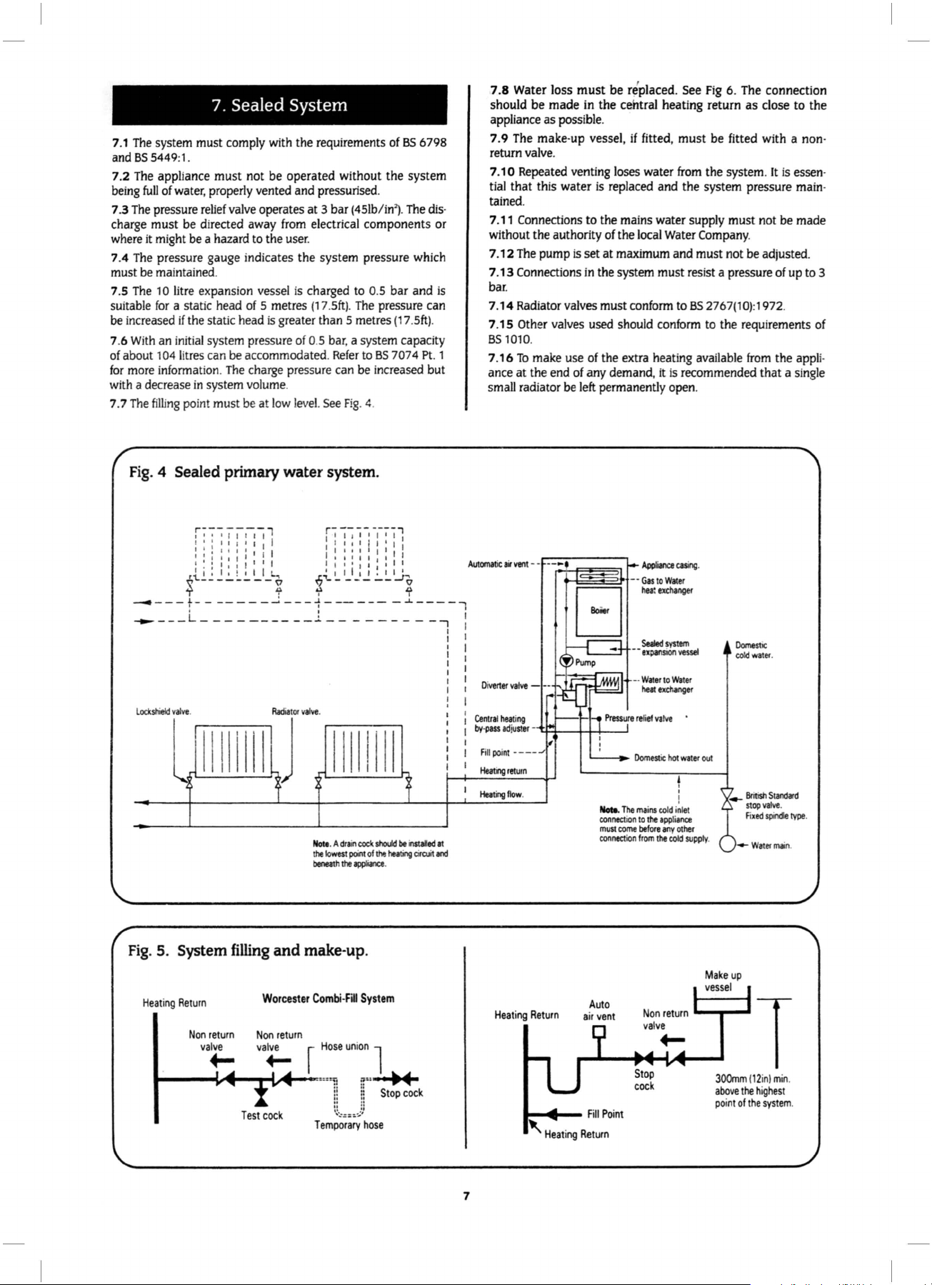
7. Sealed System
7.1
The
system must comply with the requirements of
BS
5449:
and
7.2 The appliance
being
7.3 The pressure relief valve operates
1.
must
not be operated without the system
full
of
water, properly vented and pressurised.
at
3 bar (45lb/in"). The discharge must be directed away from electrical components or
where it might be a hazard to the user.
7.4 The pressure gauge indicates the system pressure which
must be maintained.
7.5
The
10 litre expansion vessel
suitable
be increased
7.6
of
for
with a decrease
7.7
for
a static head
if
the static head
With
an initial system pressure of 0.5 bar, a system capacity
of
about 104litres can be accommodated.
more information.
The
filling
Fig.
4 Sealed primary water system.
The
charge pressure can be increased but
in
system volume.
point must be at
is
charged to 0.5 bar and
5 metres
is
(17.5ft)
greater than 5 metres
Refer
low
level.
See
Fig. 4.
. The pressure can
to
BS
BS
6798
(17
.Sft)
.
7074 Pt . 1
7.8 Water loss
be
should
must
be
r~placed
.
See
Fig
6. The connection
made in the central heating return
as
close to
the
appliance as possible.
7.9 The make-up vessel,
must be
fitted with a non-
if
fitted,
return valve.
7.
10
Repeated venting loses water from the system. it
tial
that
this water is replaced and the system pressure main-
is
essen·
tained.
Connections
7.11
without the authority of the local Water
7.1 2 The pump
Connections
7.13
is
bar.
7.14
Radiator valves must conform to
7.1
5 Other valves used should conform to the requirements of
BS
1010.
7.
16
To
make use
ance
at
the end of any demand,
to
the mains water supply must not be made
Company.
is
set
at
maximum and must not be adjusted.
in
the system must resist a pressure of up to 3
BS
2767(10):1972.
of
the extra heating available
it
is
recommended
from
that
the appli-
a single
small radiator be left permanently open.
L
ocl<shield
valve
.
l
11111
Fig.
5. System filling
Heating
Return
Non
valve
1-----t..•-
111
return
....
...
Test
Radiator
valve
J
and
Worcester
Non
return
va~
-t..•-"":=:
cock
.
I II I Ill I
Note
. A
dtm
the
beneath
make-up.
Combi-Fill
~
Temporary
c:oc:1t
lowest
point
the
appliance
Hose
union
zr,
!l
II
·:~==•.]
should
of
the
heating
.
System
l
::u
I 1
i~
Stop
II
:
hose
be
~
~
cock
installed
cir
cuit
at
and
Central
heating
by-pass adj
Fill poi
Heamg
Heating
Heating
uster
-
~+----l-+--+----J
nt
----
return
flow
.
Return
....
....,..__
'
Heating
Auto
air
vent
FiiiPoint
Return
Nola
.
The
connection
must
come
connection
Suled
system
--expansion
-·
Water
to Wat
heat
excltlnger
mains
cold inlet
to
the
appliance
before
any
from
the
other
cold
vessel
er
I
I
'
l
supply
._
.
JOOmm (12
above
point
Domestic
cold
water
British
Standard
stop
valve
Fi
xed
spindle
-Wat
er
inl
the highest
of
the
system
.
mai
min
.
type.
n.
.
.
7
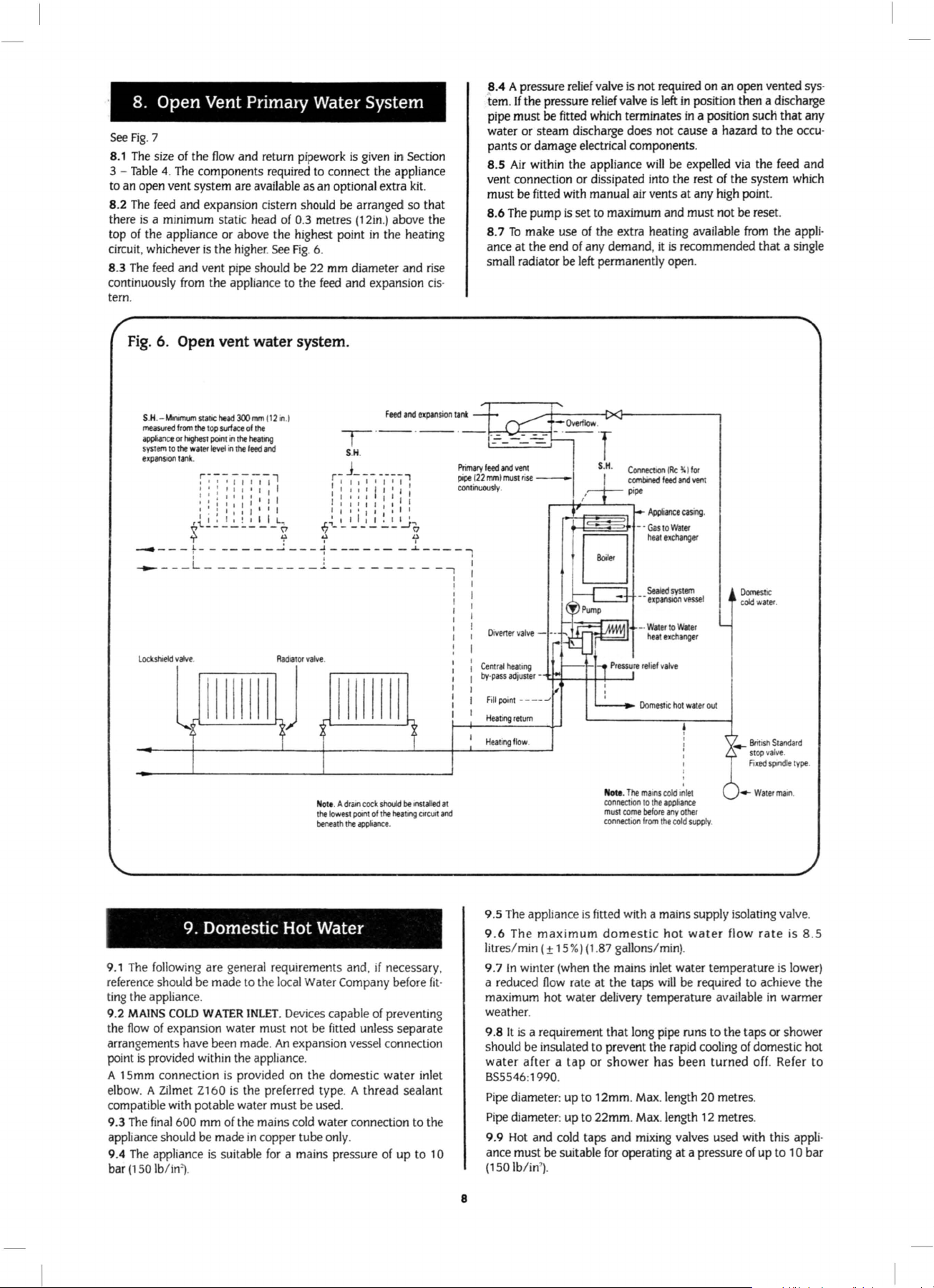
8. Open Vent Primary Water System
See
Fig
. 7
8.1
The
size of the
Thble
3 -
4.
to an open vent system are available as an optional extra
8.2
The
feed and expansion cistern should be arranged
there
is
a minimum static head of 0.3 metres (12in.) above the
top of the appliance
circuit, whichever
8.3 The feed and vent pipe should be 22 mm diameter
continuously
tern.
Fig.
6. Open vent water system.
S.H
.-
Mnmum
me85Uied
appliance
system
expansiOn
-----
- - -t----- - -
- -
flow
and return pipework
The
components required to connect the appliance
or
above the highest point
is
the higher. See Fig. 6.
from
the appliance to the feed and expansion cis·
statiC
hud
300
mm
112111
from
the
top
or
to
--L-_________
surface
t.ghest
point
in
the
wat
tank
.
,tl. I'!
\'
'T
0 I
the
er
level
in
the
;~-;--;jj1-1jl
l " " I • I I I : I I :
I I I I I I I I I I
I
I:
I I I I I I I J I I I I I I I I I
I
::
I I I I I I I :I I I I I I I I :
-
----
.1
of
the
heattng
feed
ill1d
I I
I
~
---~
• I I
_;
- - -~ -
is
given
in
-r
·- ·- ·- ·
S.H.
j
r----
.!.,
~---------'~
I I
----,
II
::I
II
I'
-----
.:.
__ ----
in
the heating
Feed
: : I I
I
I'
I I .
Section
kit.
so
that
and
rise
and
expansion
tank
Primary
pipel22mmlmustrise-
I
...
contiooously
-~ ----...,
-
---,
I
I
8.4 A pressure relief valve is not required on an open vented sys·
tern.
If
the
pressure relief valve
pipe must
be fitted which terminates
water or steam discharge does not cause a hazard to the
is
left
in
position then a discharge
in
a position such
that
any
occu·
pants or damage electrical components.
8.5 Air w
it
hin the appliance
will
be expelled via the feed
and
vent connection or dissipated into the rest of the system which
must be fitted with manual air vents
8.6 The pump
8. 7
To
ance
at
is set to maximum and must not be reset.
make use of the extra heating available from the appli·
the end of any demand,
at
any high point.
it
is
recommended
that
a single
small radiator be left permanently open .
-
Overflow
.
:-_-:_-==:
feed
ill1d
.
vent
-·- ·r
S.H.
Domest
cold
water
ic
.
lockstoeld
v...,•
l
.
tlll
Radllltor
llll
valvt.
J
llllllll
Nott
. A
dr0111
the
poont
cock
appliance
the lowest
beneath
9. Domestic Hot Water
9.1 The following are gen er
reference should be made to the local Water
ti
ng the appliance.
9.2
MAINS
COLD
WATER
flow
the
of expansion water must not be fitted unless separate
arrangements have been made.
is
provided within the appliance.
point
A 15mm connection is provided on the domestic
elbow. A
Zilmet Z160 is the preferred type. A thread
compatible with potable water must be used.
9.3
The
final
600 mm of the mains cold water connection to the
appliance should be made
9.4
The
appliance is suitable
bar (150 lb/in").
al
requirements and,
Company before
INLET
. Devices capable of preventing
An
expansion vessel connection
in
copper tube only.
for
a mains pressure of up to 1 0
should
be
of
the
heat
.
if
necessary,
water
sealant
InStalled
tng
c1r
inlet
cut
-·
Water
to
Wate
eat exchanger
'
cold 1nle1
the
appfta
nce
any
other
the
cold
supply.
r
._. Brinsn Standard
stop
valve
.
Fixed
spindle
type
....
Waterma
111
.
.
at
ill1d
Central heaung
by-pass adju
ste
F
ill
point -----'
Heating
return
Heat
ing flow
r -
~±--t+-1----'
,
.
Nota
connection
must
connection
.
The
come
h
ma.ns
to
before
from
9.5 The appliance is fitted with a mains supply isolating valve.
9.6
The
maximum
litres/min ( ± 15
9.7
In
winter (when the mains inlet water temperature is lower)
fit
·
a reduced
flow
maximum hot water delivery temperature available
domestic
%)
(1
.87 gallons/min).
rate at the taps
hot
water
flow
rate
will
be required to achieve the
in
is 8 .5
warmer
weather.
It
is
9.8
a requirement
that
long pipe runs
to
the taps
or
shower
should be insulated to prevent the rapid cooling of domestic hot
water
after a tap
or
shower
has
been
turned
off. Refer
to
BS5546:1990.
Pipe diameter: up
Pipe
diameter: up to
9.9 Hot and cold taps
ance must be suitable
(150
lb/in
').
to
12mm. Max. length 20 metres.
22mm
. Max. length 12 metres.
and
mixing valves used with this appli·
for
operating at a pressure of
up
to 1 0
bar
8

9.1 0
No
anti·syphonage arrangements are necessary except
some loose head showers.
See
also Section 9.12 following.
for
9.11 Thermostatically controlled or pressure equalising shower
will
valves
guard against the
flow
of water
at
too high a temper·
ature.
9.
12
The
head of a loose head shower must not
(1
in)
25mm
sion
an
anti·syphonage device at the po int of the
above the top edge of the bath to prevent its immer·
in
bath water. Alternatively the shower must be fitted with
fall
flexible
doser
than
hose con·
nections.
9.
13
The
supply of hot and cold mains water direct to a bidet is
permitted, (subject to local Water
vided that the bidet is of the over-rim flushing type.
Company requirements), pro-
The
outlet(s)
should be shroucded and unable to have any temporary hand
No
held spray attached.
anti-syphonage arrangements are nee·
essary.
9.14
As the maximum temperature of the Water to Water heat
is
exchanger is limited by the control drcuit, there
need for
water
treatment
to prevent scale accumulation .
normally no
In
exceptional drcumstances a device to prevent scale formation
can be fitted.
Installation of a scale inhibitor assembly should be
dance with the requirements of the local Water Company.
isolating valve should be fitted
to
allow servidng. The water
in
accor·
An
hardness can be determined using a standard test paper or by
reference to the local Water
Company.
9
1
0.
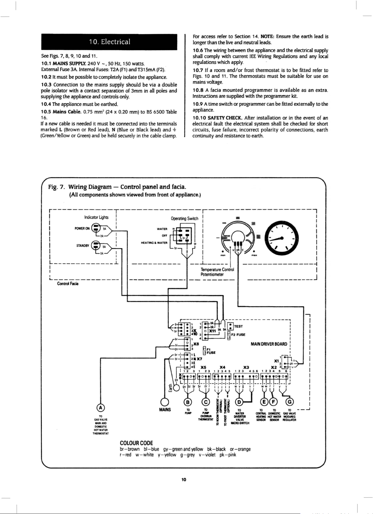
Electrical
See
Figs. 7,
8, 9,
10
and 11.
1
0.1
MAINS
External
1 0.2
1
Fuse
It
must
0.3 Connection
pole isolator
SUPPlY
3A
be
with
240 V - ,
Internal
possible
to
the mains supply should be
50
Fuses: T2A
to
completely isolate the appliance.
a contact separation
supplying the appliance and controls
1 0.4
The
appliance must
10.5 Mains Cable. 0.
16
.
If a new
marked L
(Green/'rellow
cable
is
needed it must
(Brown
or
Green)
Fig.
7. Wiring Diagram - Control
(All
be
earthed.
75 mm•
or
Red
lead), N
and
be
components
(24
x 0.
be
held
shown
Hz,
150
watts.
(F1)
and
of
T315mA
3mm
in
via
all
(F2)
poles
.
a double
and
only.
20
mm)
to
BS
6500
Thble
connected
(Blue
securely
into
the terminals
or
Black
lead) and -t
in
the
cable
clamp.
panel
and
facia.
viewed from front of appliance.)
For
access
refer
to Section 14.
longer than the
0.6
The
1
shall
comply
regulations
1
0. 7
If a room
Figs.
10
mains
voltage
0.8 A
1
Instructions
1 0. 9 A time
live
and neutral leads.
wiring
between the appliance and the
with
current
which
apply
and/
or frost thermostat
and 11.
The
thermostats must be suitable
.
facia
mounted programmer
are
supplied
switch
or
programmer can be
appliance.
1 0.10
SAFETY
electrical
circuits,
CHECK.
fault
the electrical system shall
fuse
failure
, incorrect polarity of connections, earth
continuity and resistance
NOTE: Ensure
lEE
Wiring
.
with
the programmer kit.
After
installation or
to
earth.
the earth lead
electrical
Regulations
is
and
to be fitted
any
refer
for
is
available as an extra.
fitted
externally
in
the event of
be
checked
for
supply
local
use
on
to
the
an
short
is
to
A
TO
CASVAI.Vl
IIAII
AIIO
OOIIESTlC
HOT
WATER
TltEAIIOST
AT
COLOUR
br-brown blr-red w-whi
CODE
blue gy-
te y-yellow g-grey
green
and
10
yellow
bk-black
v- vi
olet pk- pi
...,
or-orange
nk
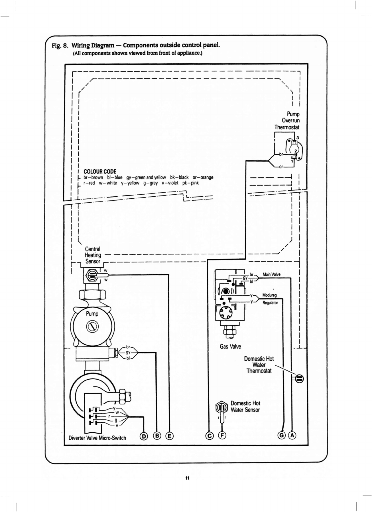
Fig.
8. Wiring Diagram - Components outside control
(All
components shown viewed
from
front
of
panel
appliance.)
r-------------
,r------------
/ ' I
/ ' I
-------
-------
----
-------l
-----~
r i 1
l I I
I
I
I
I
I
I
I
I
I
I
I
COLOUR
~
br-brown bl-blue
J-
r-red w-white y-yellow g-grey
I ·- ·- ·- ·.
I · - .
-~-
-
'T ·- ·- ·
CODE
--
-----·--
·
.---
gy-green
· - ·
and
-·-
I I
I I
I I
I I
I
~
I
I
I
I
-------------
I
br
gy~--..
bl
yellow
bk-black
v-violet pk-pink
-::::
·.=;!
.
L-.
L.--
or-orange
·-
----
----
Gas
Valve
-----1
_____
-=·.-::::.·.::=:
-----//
-------
Main
Modureg
Regulator
Domestic
Water
Thermostat
Overrun
Thermostat
_ .
.- -
Valve
Hot
'-...!...
1
Pump
_J
...J...-1...
Tj
I I
I I
I I
I I
I I
/)
-i
-
1
~
I
I
.
·
I
I
I
I
I
I
I
I
I
I
I
I
I
...J...
Diverter
Valve
Micro-Switch
11
Domestic
Water
Sensor
Hot
 Loading...