

Bosch Wallscanner D-tect 150 Operating/safety Instructions Manual
O
PE
N
O
P
E
N
S
t
a
r
t
S
e
t
u
p
W
a
l
l
sc
a
nn
e
r
D-
t
ec
t
1
5
0
IMPORTANT: IMPORTANT : IMPORTANTE:
Read Before Using Lire avant usage Leer antes de usar
Operating/Safety Instructions
Consignes de fonctionnement/sécurité
Instrucciones de funcionamiento y seguridad
Wallscanner
D-tect™150
For English Version Version française Versión en español
See page 6 Voir page 17 Ver la página 29
1-877-BOSCH99 (1-877-267-2499) www.boschtools.com
Call Toll Free for
Consumer Information
& Service Locations
Pour obtenir des informations
et les adresses de nos centres
de service après-vente,
appelez ce numéro gratuit
Llame gratis para
obtener información
para el consumidor y
ubicaciones de servicio
-2-
P
r
o
f
e
s
s
i
o
n
a
l
D
-
T
E
C
T
1
5
0
P
r
o
f
e
s
s
i
o
n
a
l
D
-
T
E
C
T
1
5
0
P
r
o
f
e
s
s
i
o
n
a
l
D
-
T
E
C
T
1
5
0
P
r
o
f
e
s
s
i
o
n
a
l
D
-
T
E
C
T
1
5
0
D
-
T
E
C
T
1
50
S
E
NSO
R
OP
E
N
OP
E
N
S
t
a
r
t
S
e
t
up
W
a
l
l
s
c
a
n
n
e
r
D
-
t
e
c
t
1
5
0
2
1
6
7
8
9
3
4
5
14
13
15
1618
17
11
10
12
3
0
8
2
8
C
2
D-
t
ec
t
1
5
0
3
6
01
K
1
0
01
3
4
x
A
A
1
.
5
M
a
d
e
i
n
G
e
r
m
an
y
T
hi
s
d
e
vi
c
e
c
o
m
p
l
i
e
s
w
i
t
h
P
a
r
t
1
5
o
f
th
e
F
C
C
R
ul
e
s
.
O
p
e
r
a
t
i
o
n
i
s
s
u
b
j
e
ct
t
o
th
e
f
o
l
lo
w
i
ng
t
w
o
c
o
n
d
i
t
i
o
n
s
:
1
.
)
T
his
de
v
i
c
e
m
ay
n
o
t
c
a
use
h
a
r
m
f
ul
i
n
t
e
r
f
e
r
en
ce,
a
nd
2
.
)
T
h
i
s
d
ev
i
c
e
m
u
s
t
a
c
c
e
p
t
a
n
y
i
n
t
e
r
f
er
en
c
e
re
c
e
i
v
e
d
,
i
n
cl
u
d
ing
i
n
t
er
f
e
re
n
c
e
t
ha
t
m
a
y
cau
s
e
un
d
es
i
r
e
d
o
p
e
r
a
t
i
o
n
.
F
C
C
I
D
:
T
X
T
-
DTE
C
T
1
5
0
A
I
C
-
I
D
:
9
0
9
H
-
DT
E
C
T1
5
0
A
R
o
b
e
r
t
B
o
sc
h
T
o
o
l
C
o
r
p.
M
o
u
n
t
P
r
o
spe
c
t
,
I
L
-3-
Concrete
Prev Next
Sensor
N
S
1.5 cm
6
4
2
0 cm
6
4
2
88
0 cm
Concrete
e
Sensor
3.5 cm
O
P
E
N
S
t
a
r
t
S
e
t
u
p
O
P
E
N
S
t
a
r
t
S
e
t
u
p
O
P
E
N
S
t
a
r
t
S
e
t
u
p
O
P
E
N
S
ta
r
t
S
e
t
u
p
O
P
E
N
S
t
a
r
t
S
e
t
u
p
O
P
E
N
S
t
a
r
t
S
e
t
u
p
OPEN
St
a
rt
S
e
tu
p
OPEN
Start
Setup
O
P
E
N
St
a
rt
Set
u
p
OPEN
Start
Setup
OP
EN
Sta
rt
Setu
p
OPEN
Start
Setup
Concrete
e
Sensor
3.5 cm
Concrete
Prev Next
6
4
2
0 cm
6
4
2
88
0 cm
Sensor
N
S
3.5 cm
l
m
j
e
f
d
a
b
n
c
h
e
i
g
k
f
g
A
C
B
-4-
Drywall
Prev. Next
Sensor
Metal
?
0.5 cm
6
4
2
0 cm
6
4
2
88
0 cm
Concrete
Prev. Next
Sensor
?
N
S
4.0 cm
6
4
2
0 cm
6
4
2
88
0 cm
Deep concrete
Prev. Next
Sensor
?
N
S
8.8 cm
15
12
9
6
3
0 cm
15
12
9
6
3
0 cm
D
F
E
-5-
O
P
E
N
S
t
a
r
t
S
e
t
u
p
OP
E
N
S
t
a
r
t
Se
t
u
p
O
P
E
N
S
t
a
r
t
S
e
t
u
p
OPE
N
S
t
a
r
t
Se
t
u
p
O
P
E
N
S
t
a
r
t
S
e
t
u
p
OP
E
N
S
t
a
r
t
Se
t
u
p
Concrete
Prev. Next
Sensor
?
N
S
?
?
0.0 cm
6
4
2
0 cm
6
4
2
88
0 cm
Concrete
Prev. Next
Sensor
?
N
S
2.0 cm
6
4
2
0 cm
6
4
2
88
0 cm
G
I
H

-6-
Read all instructions. Failure to follow all instructions listed below may result in electric
shock, fire and/or serious injury.
SAVE THESE INSTRUCTIONS
The detector’s ability to detect objects is affected by the proximity of other equipment
that produce strong magnetic or electromagnetic fields, and by moisture, metallic
building materials, foil-laminated insulation materials and/or conductive wallpaper.
The detector’s ability to detect wood substructures (studs) is also affected by inconsistency on the
thickness of the surface material, such as plaster and lath.
It is possible that there may be metal, wood or wiring or something else, such as plastic pipes, beneath
the scanned surface that is not detected.
The detector alone should not be relied on exclusively to locate items below the
scanned surface. Use other information sources to help locate items before penetrating
the surface. Such additional sources include construction plans, visible points of entry of pipes and
wiring into walls, such as in a basement, and standard 16” and 24” stud spacing practices.
Before penetrating a surface (such as with a drill, router, saw or nail), always shut off
the electrical power, gas and water supplies. Cutting, drilling, etc… into these items
when operational can result in personal injury.
For technological reasons, the measuring tool cannot ensure 100 % certainty. To
rule out hazards, safeguard yourself each time before drilling, sawing or routing
in walls, ceilings or floors by means of other information sources, such as building plans,
pictures from the construction phase, etc. Environmental influences, such as humidity or closeness
to electrical devices, can influence the accuracy of the measuring tool. Surface quality and condition of
the walls (e. g., moisture, metallic building materials, conductive wallpaper, insulation materials, tiles)
as well as the amount, type, size and position of the objects can lead to faulty measuring results.
FCC Statement
Warning: Changes or modifications to this unit not expressly approved by the party responsible for
compliance could void the user’s authority to operate the equipment.
Note: This equipment has been tested and found to comply with the limits for a Class B Digital device,
pursuant to Part 15 of the FCC Rules. These limits are designed to provide reasonable protection
against harmful interference in a residential installation. This equipment generates, uses, and can
radiate radio frequency energy and, if not installed and used in accordance with the instructions, may
cause harmful interference to radio communications. However, there is no guarantee that interference
will not occur in a particular installation. If this equipment does cause harmful interference to radio or
television reception, which can be determined by turning the equipment off and on, the user is
encouraged to try to correct the interference by one or more of the following measures:
– Reorient or relocate the receiving antenna.
– Increase the separation between the equipment and receiver.
– Connect the equipment into an outlet on a circuit different from that to which the receiver is
connected.
– Consult the dealer or an experienced radio TV technician for help.
General Safety Rules
!
WARNING
!
WARNING
!
WARNING
!
WARNING
Section 15.525 Coordination requirements.
(a) UWB imaging systems require coordination through the FCC before the equipment may be used.
The operator shall comply with any constraints on equipment usage resulting from this coordination.
(b) The users of UWB imaging devices shall supply operational areas to the FCC Office of Engineering
and Technology, which shall coordinate this information with the Federal Government through the
National Telecommunications and Information Administration. The information provided by the UWB
operator shall include the name, address and other pertinent contact information of the user, the desired
geographical area(s) of operation, and the FCC ID number and other nomenclature of the UWB device.
If the imaging device is intended to be used for mobile applications, the geographical area(s) of operation
may be the state(s) or county(ies) in which the equipment will be operated. The operator of an imaging
system used for fixed operation shall supply a specific geographical location or the address at which the
equipment will be
operated. This material shall be submitted to the following address:

Frequency Coordination Branch, OET
Federal Communications Commission
445 12th Street, SW
Washington, D.C. 20554
Attn: UWB Coordination
(c) The manufacturers, or their authorized sales agents, must inform purchasers and users of their
systems of the requirement to undertake detailed coordination of operational areas with the FCC prior
to the equipment being operated.
(d) Users of authorized, coordinated UWB systems may transfer them to other qualified users and to
different locations upon coordination of change of ownership or location to the FCC and coordination
with existing authorized operations.
(e) The FCC/NTIA coordination report shall identify those geographical areas within which the operation
of an imaging system requires additional coordination or within which the operation of an imaging
system is prohibited. If additional coordination is required for operation within specific geographical
areas, a local coordination contact will be provided. Except for operation within these designated areas,
once the information requested on the UWB imaging system is submitted to the FCC no additional
coordination with the FCC is required provided the reported areas of operation do not change. If the
area of operation changes, updated information shall be submitted to the FCC following the procedure
in paragraph (b) of this section.
(f) The coordination of routine UWB operations shall not take longer than 15 business days from the
receipt of the coordination request by NTIA. Special temporary operations may be handled with an
expedited turn-around time when circumstances warrant. The operation of UWB systems in emergency
situations involving the safety of life or property may occur without coordination provided a notification
procedure, similar to that contained in Section 2.405(a) through (e) of this chapter, is followed by the
UWB equipment user.
For Canadian Customers only
This In-wall Radar Imaging Device shall be operated where the device is directed at the wall and in
contact with or within 20 cm of the wall surface. This In-wall Radar Imaging Device shall be operated
only by law enforcement agencies, scientific research institutes, commercial mining companies,
construction companies, and emergency rescue or firefighting organizations.
-7-
WARNING: Batteries can explode or leak, and can
cause injury or fire. To reduce this risk:
ALWAYS follow all instructions and warnings on
the battery label and package.
DO NOT short any battery terminals.
DO NOT charge alkaline batteries.
DO NOT mix old and new batteries. Replace all of
them at the same time with new batteries of the
same brand and type.
DO NOT mix battery chemistries.
DISPOSE of batteries per local code.
DO NOT dispose of batteries in fire.
KEEP batteries out of reach of children.
REMOVE batteries if the device will not be used for
several months.
Electrical Safety Procedures
Environment Protection
Recycle raw materials & batteries instead of disposing of waste. The unit, accessories, packaging & used
batteries should be sorted for environmentally friendly recycling in accordance with the latest regulations.
-8-
INTENDED USE
The detection tool is intended for the detection of
metals (ferrous and non-ferrous metals, such as
pipes, metal studs and rebar), wood studs, plastic
pipes (>1” in diameter) and joists, and “live”
wires/conductors in walls, ceilings and floors.
PRODUCT FEATURES
The numbering of the product features shown
refers to the illustration of the detection tool on the
graphic page.
1 Marking guide, top
2 Wheel
3 Marking guide, left and right
4 Battery lid
5 Latch of battery lid
6 Handle
7 Maintenance cover
8 Serial number
9 Sensor area
10 Selection button, right
11 Start button
12 Selection button, left
13 Audio signal button
14 Setup button
15 On/Off button
16 Display
17 LED
18 Protective soft case
The accessories illustrated or described are not
included as standard delivery.
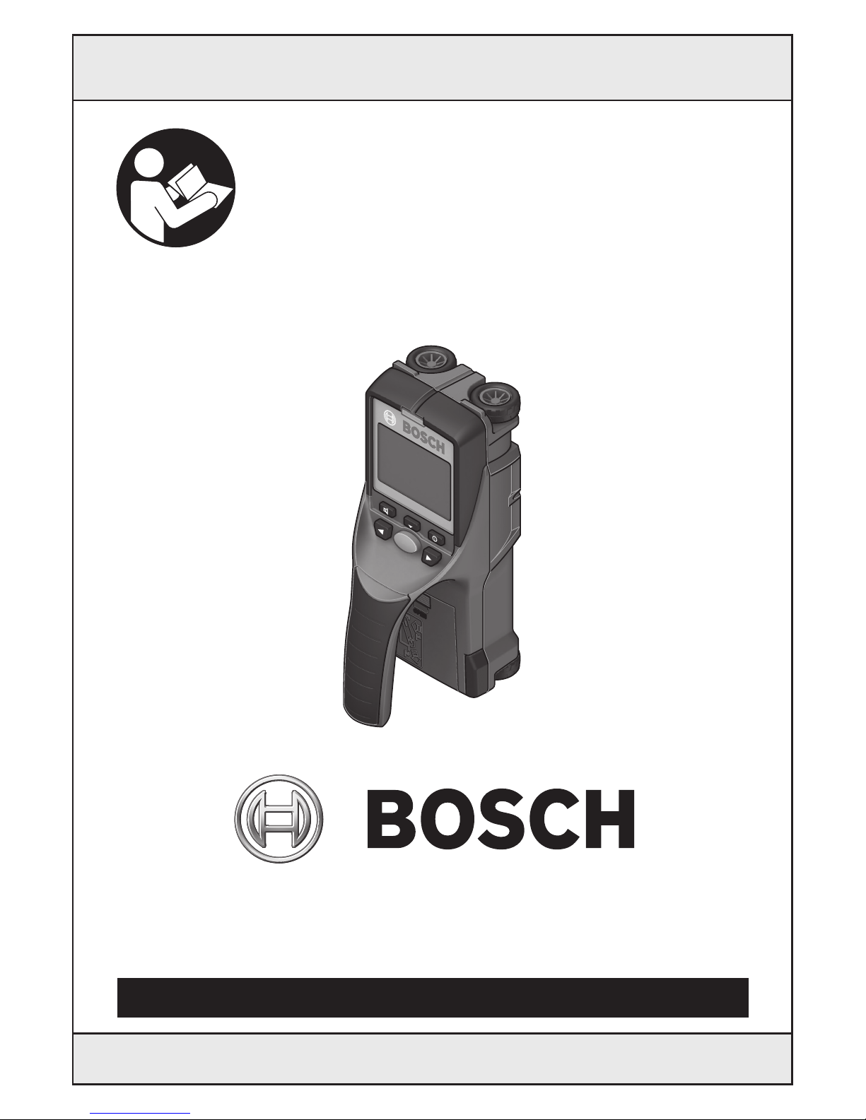
DISPLAY ELEMENTS
a Audio signal indicator
b Battery indicator
c Sensor-range indicator
d Area already detected
e Measuring scale for object depth
f Area not yet detected
g Outer edges, to be marked left and right via
marking guide 3
h Mode indicator
i Gray: Found object outside of the
sensor range
j Black: Found object within the sensor range
k Center line, corresponds with the marking
guide
1
l Object depth indicator
m Object material indicator
n “Live” wire indicator
Optimal operation of the detection tool is possible only when the operating instructions and information are
read completely, and the instructions contained therein are strictly followed.
Functional Description
Setup
Start
-9-
Wallscanner D-tect™150
Technical Data
1) Depending on size and type of object as well as
material and condition of the base material.
In terms of accuracy, the measuring result
can be inferior in case of unfavorable surface
quality of the base material.
2) See graphic
Please observe the article number on the type plate
of your detection tool. The trade names of the
individual detection tools may vary.
The detection tool can be clearly identified with the
serial number 8 on the type plate.
Article number
Dimensions
Measuring accuracy to the object
center a
2)
Accuracy of the displayed object depth b
2)
– in dry concrete
– in wet concrete
Minimum distance between two neighboring
objects c
2)
Operating temperature
Storage temperature
Batteries
Battery service life, approx.
–Batteries (Alkali-manganese)
Weight according to EPTA-Procedure 01/2003
Protection class
3 601 K10 013
8 21/32” x 3 13/16 x 4 23/32”
(220 x 97 x 120 mm)
±3/16 in (±5 mm
1)
)
±3/16 in (±5 mm
1)
)
±3/8 in (±10 mm
1)
)
1 7/32 in (4cm
1)
)
+14°F … + 122°F
C
(– 10 °C ... +50 °C)
– 4 °F ... +158 °F
(–20 °C ... +70 °C)
4 x 1.5 V AA (LR06)
5 Hours
1.5lb (0.7 kg)
IP 54 (dust and splash water protected)
c
b
a

-10-
Inserting/Replacing the Battery
To open the battery lid 4, press the latch 5 in the
direction of the arrow and remove the battery lid.
Insert the batteries. When inserting, pay attention
to the correct polarity according to the
representation on the inside of the battery
compartment.
The battery indicator b in the upper status line on
the display 16 indicates the charge condition of
the batteries.
Note: Pay attention to the changing battery
symbol so that the batteries are replaced in time.
When the “Please change batteries” warning
indication is shown on the display 16, the settings
are saved and the detection tool switches off
automatically. Measurements are no longer
possible. Change the batteries.
To remove the batteries, press on the back of a
battery as indicated in the figure on the battery lid
(1). The front end of the battery is released from
the battery compartment (2), so that the battery
can easily be removed.
Always replace all batteries at the same time. Do
not use different brands or types of batteries
together.
• Remove the batteries from the detection
tool when not using it for extended periods.
When storing for long periods of time, the
batteries can corrode and discharge themselves.
Preparation
INITIAL OPERATION
• Protect the detection tool against moisture
and direct sunlight.
• If the detection tool was subject to an extreme
temperature change, allow it to adjust to the
ambient temperature before switching on.
In case of extreme temperature or variations in
temperature, the accuracy of the detection tool
and the display can be impaired.
• Do not attach any stickers or labels to the
sensor area 9 on the back of the detection
tool. Metal nameplates can affect the detection
results.
• Use or operation of transmitting systems,
such as WLAN, UMTS, radar, transmitter
antenna or microwaves in the close proximity
can influence the detection function.
Switching On and Off
• Before switching the detection tool on, make
sure that the sensor area 9 is not moist.
If required, dry the detection tool using a soft
cloth.
Switching On
– To switch on the detection tool, press the
On/Off button 15 or the start button 11.
– LED 17 lights up green and the start display is
indicated on display 16.
– When no measurement is carried out and no
button is pressed for 5 minutes, the detection
tool switches off automatically. This “Cut-off
time” can be changed in the “Settings” menu
(see “Cut-off Time”, page 12).
Switching Off
– To switch the detection tool off, press the On/Off
button 15.
– When switching off the detection tool, all
settings are retained in the menus.
Switching the Audio Signal On/Off
The audio signal can be switched on/off with the
audio signal button 13. The “Tone signal” can be
changed in the “Settings” submenu (see “Tone
Signals”, page 12).
Operation
Please change batteries

-11-
METHOD OF OPERATION
(SEE FIGURE B)
The detection tool checks the
base material of sensor area 9 in
measurement direction A to the
displayed measuring depth.
Measurement is possible only
during movement of the detection
tool in the direction of travel B and
for a measuring distance of at
least 4” 10 cm. Move the
detection tool in a straight line
with light pressure over the wall
so that the wheels remain in firm contact with
the wall. The object depth and, if possible, the
object material, are indicated on the display.
Optimal results are achieved when the measured
distance is at least 15 3/4” (40 cm) and the
detection tool is moved slowly over the entire
location. This method of operation ensures reliable
detection of outer object edges that run transverse
to the detection tool’s movement direction.
Always move crossways over the area to be
checked.
If several objects are located one over the other in
the wall, the object that is indicated in the display
is the one nearest to the surface.
The representation of the material types of
detected objects in the display 16 can deviate from
the actual object material types. This applies
particularly for very thin objects, which are
represented thicker in the display. Large cylindrical
objects (e.g. plastic or water pipes) can appear in
the display smaller than they actually are.
Detectable Objects
– Plastic pipes (e.g. water-filled plastic pipes, as
used in floor/wall-heating systems, with at least
3/4” in diameter; empty pipes with at least 1” in
diameter)
– Electrical wiring (independent of whether
carrying voltage or not)
– Three-phase wiring (e.g. to the stove)
– Low-voltage wiring (e.g. for door bell,
telephone)
– Metal pipes, bars, studs of any type (e.g. steel,
copper, aluminium)
– Reinforcing steel
– Wooden studs
– Hollow spaces
Measurements possible
– In concrete/reinforced concrete
– In brickwork (bricks, porous concrete, foam
concrete, aerated concrete, lime-sand brick)
– In light construction walls
– Under surfaces such as stucco, tiles, wallpaper,
hardwood flooring, carpet
– Behind wood, drywall
Special Measuring Cases
Based on the measuring priniciple, unfavorable
conditions can influence the measuring result, for
example:
– Multi-layered walls
– Empty plastic pipes and wood studs in hollow
spaces and light construction walls
– Objects running inclined in walls
– Moist walls
– Metal surfaces
– Hollow spaces in a wall; these can be indicated
as objects.
– Closeness to equipment that generates a
strong magnetic or electromagnetic field, e.g.
radio stations or generators.
MEASURING PROCEDURE
Switch the detection tool on. The “standard start
display” appears on display 16.
Position the detection tool against the wall and
move it over the wall in the direction of travel (see
“Operation Instructions”, page 13). Measured
results are indicated on display 16 after a
minimum measuring distance of 4” (10 cm). To
ensure correct measurement results, move the
detection tool slowly and completely over the
assumed object in the wall.
If the detection tool is lifted away from the wall
during a measurement or not operated (moving
the device or pressing a button) for more than 2
minutes, the last measured result remains on the
display. “Hold” appears on the sensor-range
indicator c. When the detection tool is placed
against the wall again, moved on or when the start
button 11 is pressed, the new measurement will
start.
When LED 17 lights up red, an object is in the
sensor range. When LED 17 lights up green, no
object is in the sensor range. When LED 17
flashes, “live” wires / conductors are in the
sensor range.
S
E
NS
O
S
E
NS
R
A
B
B
9
Sensor
Concrete
txeNverP
Move
6
4
2
0 cm
6
4
2
88
0 cm
-12-
Before drilling, sawing or routing
into a wall, protect yourself
against hazards by using other information
sources. As the measuring results can be influenced
through ambient conditions or the wall material, there
may be a hazard even though the indicator does not
indicate an object in the sensor range (no audio
signal or beep and the illuminated ring 17 lit green).
Display Elements (see figure A)
If an object is under the sensor area, it will appear
in the sensor range c of the display. Identification
of material type depends on size and depth of
object. The object depth l to the upper edge of the
found object found is indicated in the status line.
Note: Both the indication of the object depth l as
well as the material type m refer to the object
pictured black in the sensor area.
The indication of the object material m can
represent the following characteristics:
– Magnetic, e.g. reinforcing steel
– Non-magnetic, but metal, e.g. copper pipe
– Non-metal, e.g. wood or plastic
– Material type unknown
The indication of “live” wires n can represent the
following characteristics:
– “Live”
Note: For “live” wire/conductors, no further
characteristic is displayed.
– Not definite whether “live” or voltage free
Note: Three-phase wiring are possibly not
detected as “live” conductors.
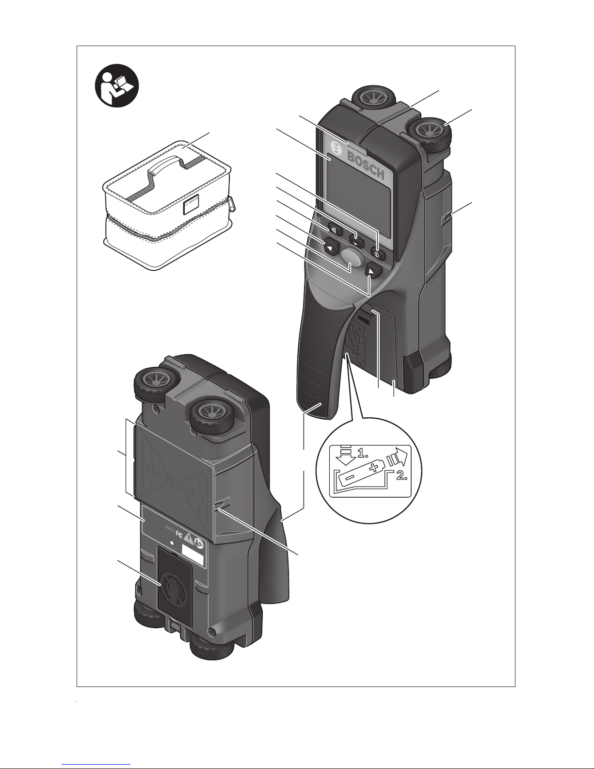
Object Detection
To detect objects, moving over the measuring path
once may be enough.
When no object is found, repeat the motion
perpendicular to the initial measuring direction
(see “Operation Instructions”, page 13).
For precise detection and marking of an object,
move the detection tool back over the
measuring path.
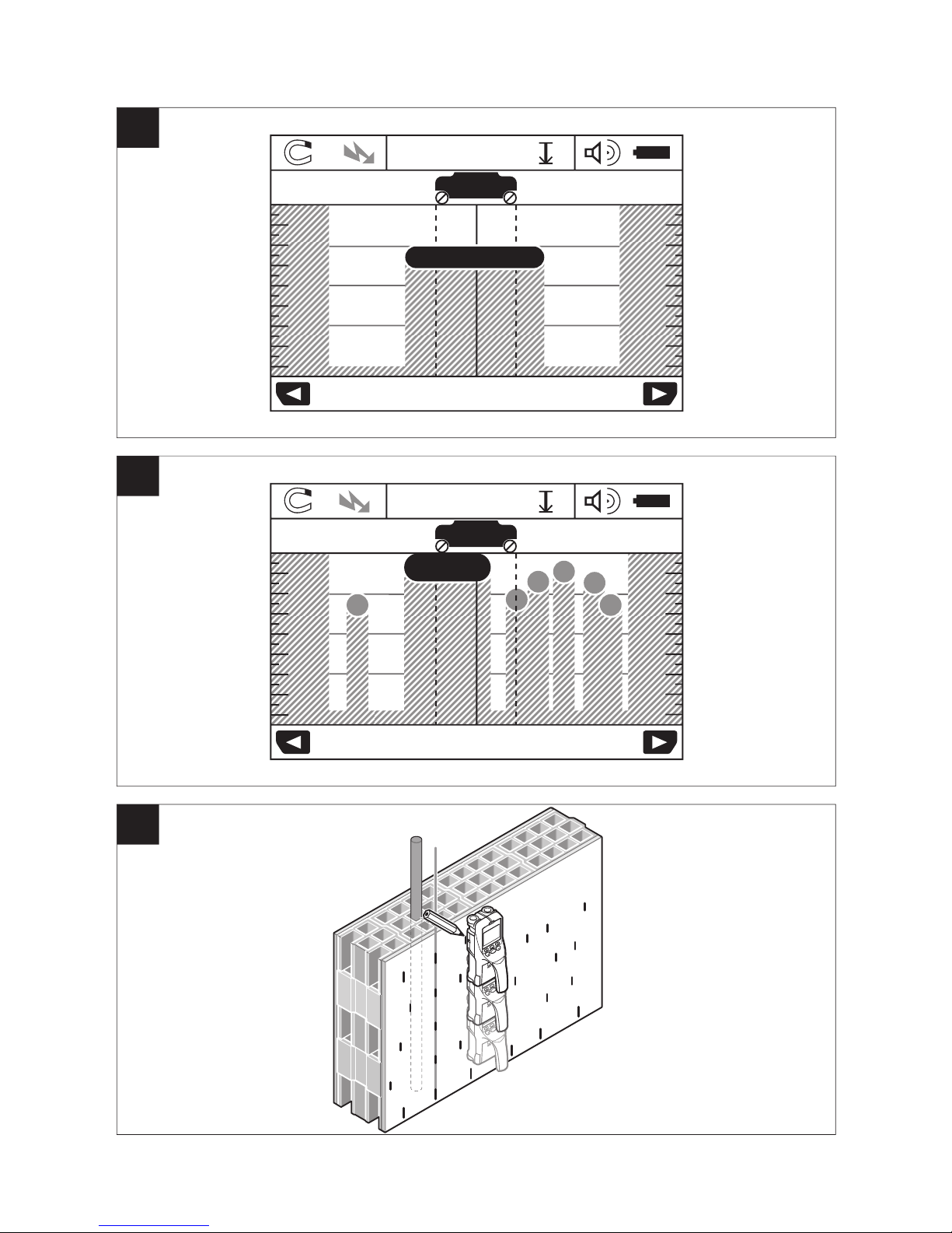
When an object is indicated directly below the
center line k in display 16, as in the example, mark
it roughly with the top marking guide 1. This mark
will only be precise when the object is positioned
exactly vertical in the wall, as the sensor range is
located somewhat below the top marking guide.
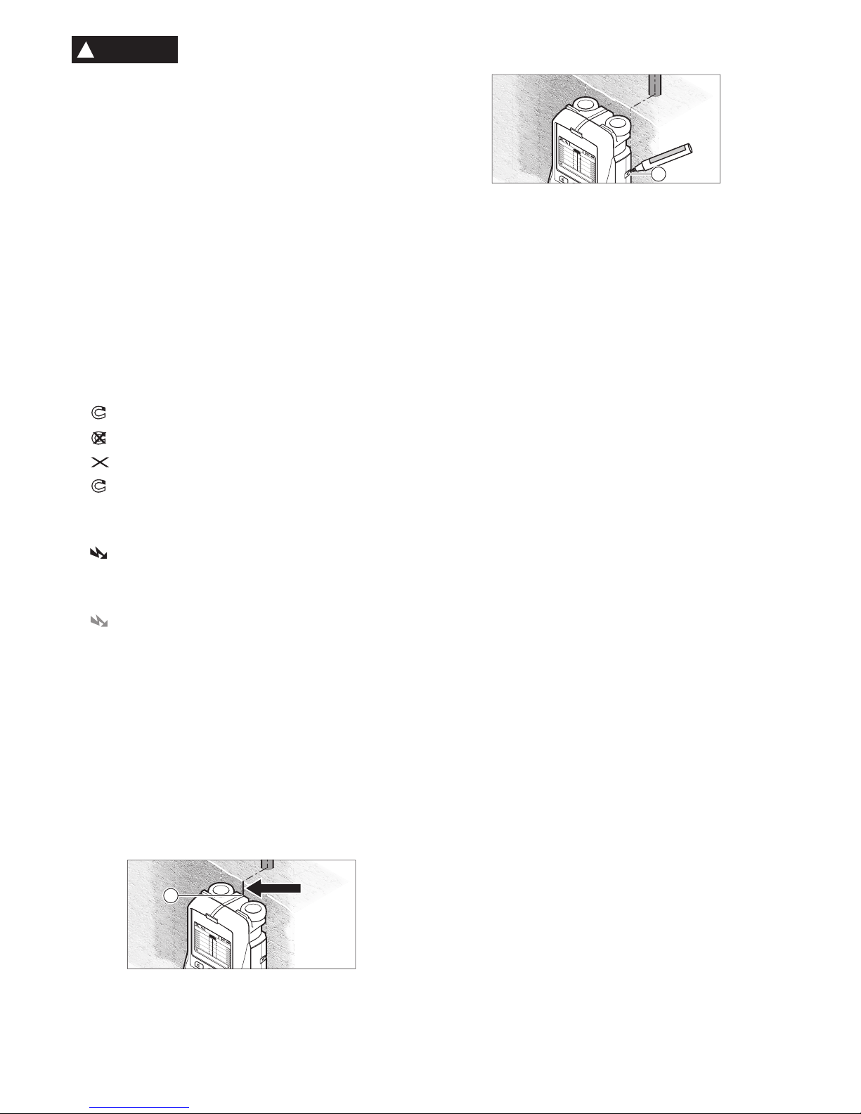
For exact marking of the object on the wall, move
the detection tool left or right until the found object
is positioned below one of the outer edges. When
the found object is indicated directly below the
dashed righthand line g in display 16, mark it with
the right marking aid 3.
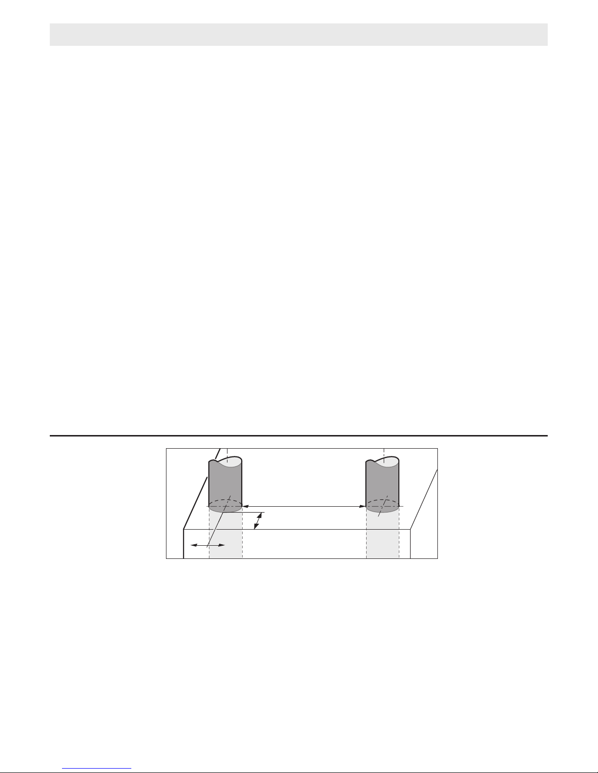
The direction of an object found in a wall can be
determined by carrying out several offset
measurements one after another (see figure I and
“Examples for Measuring Results”, page 13). Mark
and connect the respective measuring points.
By pressing the start button 11, the display of the
objects found can be deleted at any time and a
new measurement started.
CHANGING THE
OPERATING MODES
Changing between different operating modes is
possible with selection buttons 10 and 12.
– Briefly press selection button 10 to select the
next operating mode.
– Briefly press selection button 12 to select the
previous operating mode.
By selecting the operating modes, you can adapt
the detection tool to different wall materials. The
current setting is always shown in the operatingmode indication h of the display.
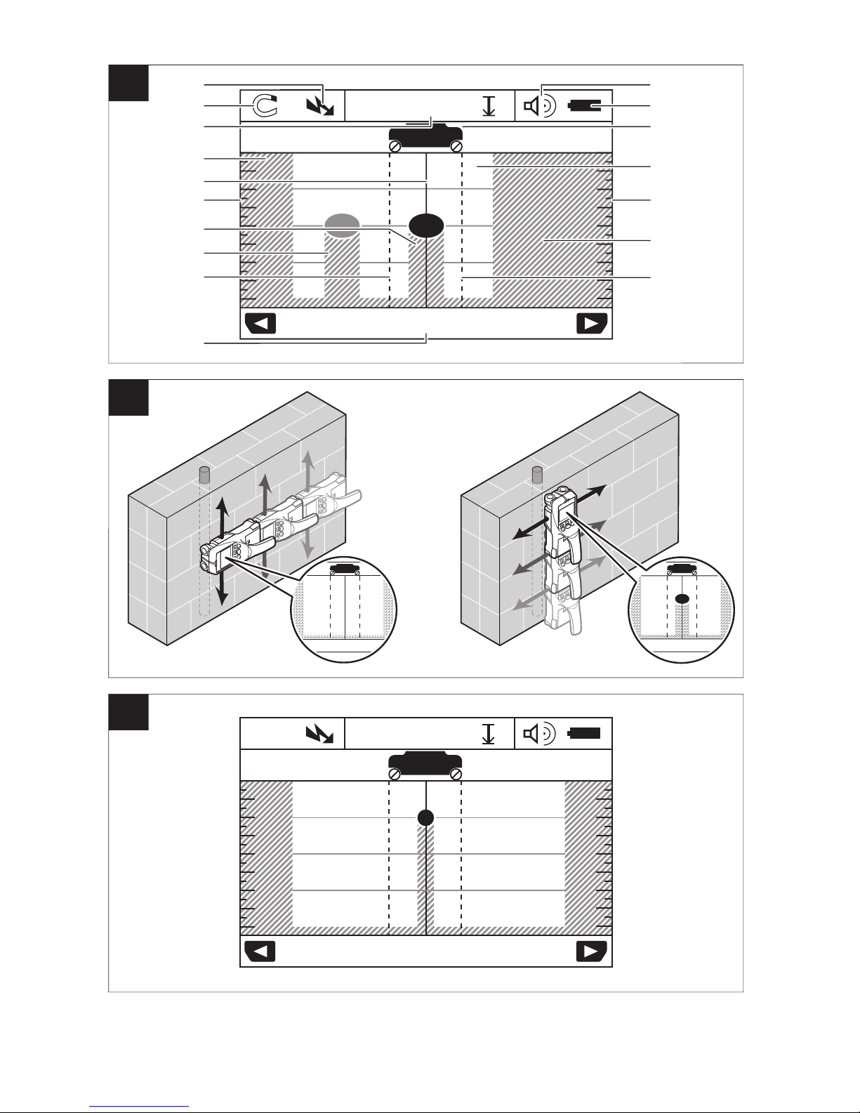
Concrete
“Concrete” is suitable for most applications in
brickwork or concrete. Plastic and metal objects
as well as electrical wiring are displayed. Hollow
spaces in brickwork or empty plastic pipes with a
diameter of less than 1” may not be displayed. The
maximum measuring depth is 3-1/8”.
Wet Concrete
The operating mode “ Wet Concrete” is
particularly suitable for applications in wet
reinforced concrete. Reinforcing steel, plastic and
metal pipes, as well as electrical wiring are
displayed. Differentiating between “live” and
voltage-free conductors is not possible. The
maximum detection depth is 2-3/8”.
Please note that concrete requires several months
to dry completely.
Deep Concrete
The operating mode “Deep Concrete ” is
particularly suitable for detecting objects
embedded deep in reinforced concrete.
Reinforcing steel, plastic and metal pipes, as well
as electrical wiring are displayed. The maximum
N
S
N
S
Metal
N
S
?
?
?
C
o
n
c
r
e
t
e
P
r
e
v
N
e
x
t
S
en
s
o
r
N
S
1
.
5
cm
6
4
2
0 c
m
6
4
2
8
8
0 c
m
1
C
o
n
c
r
e
t
e
P
r
e
v
N
e
x
t
S
e
n
s
o
r
N
S
1
.
5
c
m
6
4
2
0
cm
6
4
2
8
8
0
c
m
3
!
WARNING
-13-
detecting depth is 6”.
When too many objects are displayed, it may be
possible that you are moving directly alongside a
reinforcement rod. In this case, place the detection
tool a few inches aside and try again.
In-floor heating
The operating mode “In-floor heating” is
particularly suitable for detecting metal, metalcomposite and water-filled plastic pipes, as well as
for electrical wiring. Empty plastic pipes are not
displayed. The maximum measuring depth is
3-
1/8”.
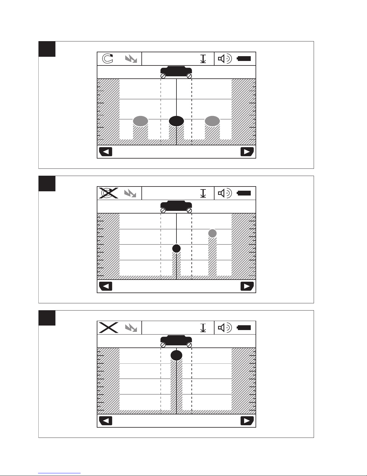
Drywall
The operating mode “Drywall” is suitable for
finding wooden beams, metal framing and
electrical wiring in drywalls (wood, gypsum board,
drywall, etc.). Filled plastic pipes and wooden
studs are displayed identically. Empty plastic pipes
are not detected. The maximum measuring depth
is
3-1/8”
.
Metal
The operating mode “Metal” is suitable for
detecting metal objects and “live” wires / conductors when other operating modes in different wall
situations do not provide satisfactory results. In such
cases, the detection results will be more extensive,
yet less precise.
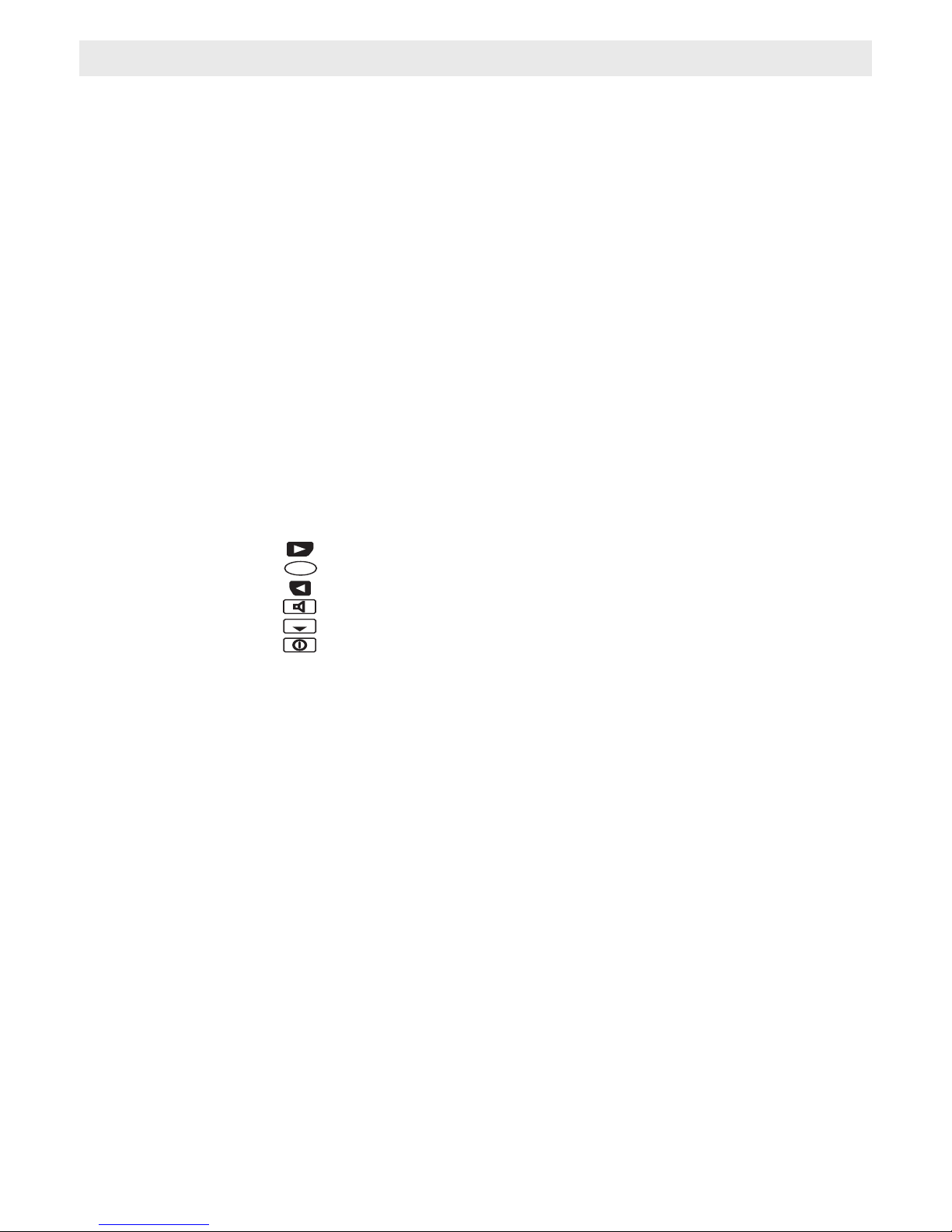
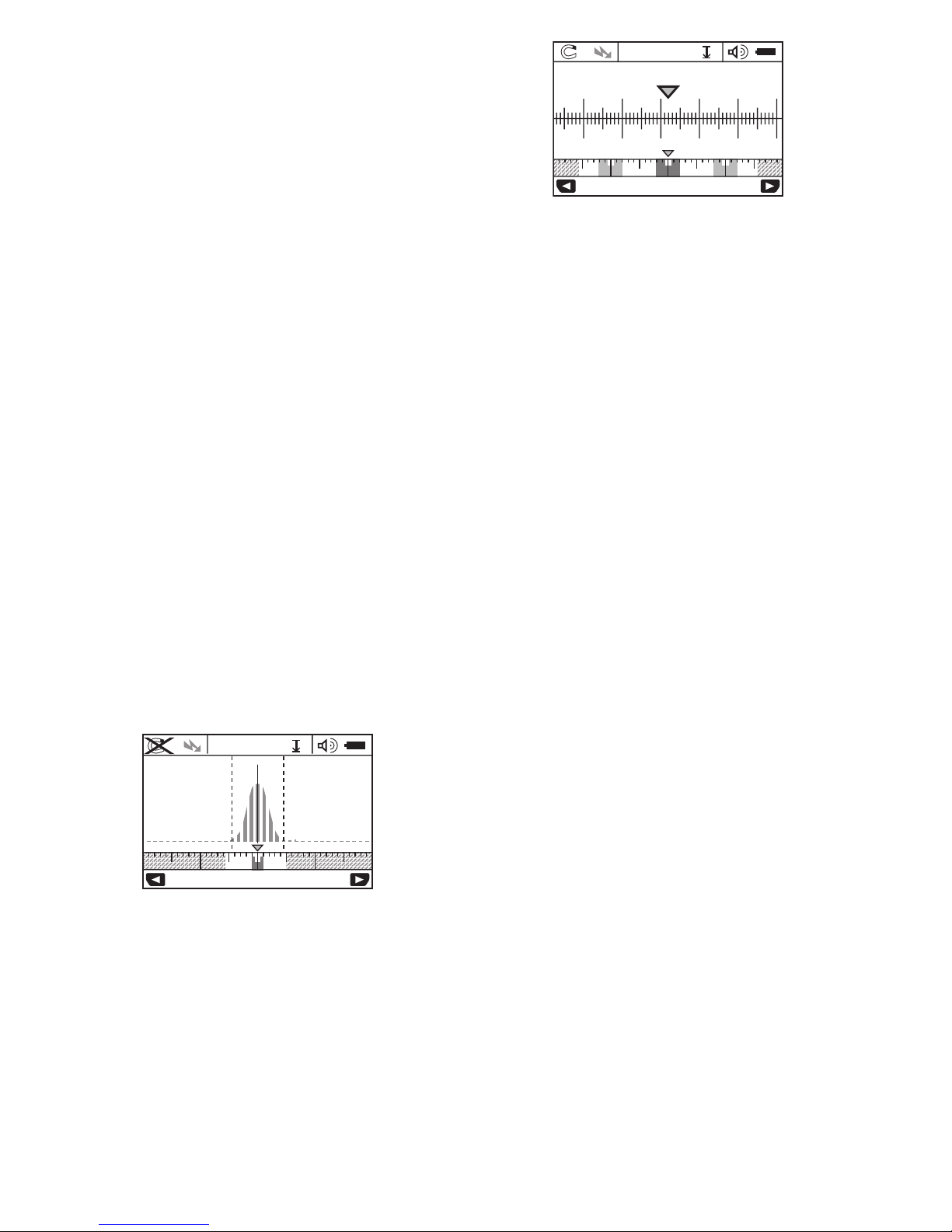
Signal View Mode
The operating mode “Signal view” is suitable for
all materials. The signal strength at the
corresponding detection position is displayed. This
mode is particularly suitable for better evaluation
of complicated material structures based on the
characteristic of the signal.
The object depth and the material types (as far as
possible) are displayed. The maximum measuring
depth is 6”.
• The signal strength shown on the main
display is not directly related to the object
depth.
CHANGING THE DISPLAY MODES
Note: Changing the display modes is possible in
any operating mode.
To switch from the standard start display to rule
mode, press and hold selection button 10 or 12.
In the example, ruler mode shows the same
situation as in figure D: Three steel bars equally
apart. In rule mode, the clearance between the
detected object centers can be determined.
The measuring distance covered from the starting
point (in the example 20.1 cm) is displayed under
the indication of the object depth l.
The three objects are displayed as rectangles in
the small ruler above the operating-mode
indication h.
Note: Both the indication of the object depth l as
well as the material type m refer to the object
pictured black in the sensor area.
To return to the standard start display, briefly press
selection button 10 or 12.
Note: Only the display is reset, not the measuring
mode!
“SETTINGS” MENU
To access the “Settings” menu, press the setup
button 14.
To exit the menu, press the start button 11. The
current settings are saved. The standard start
display for the measuring process is activated.
Navigating in the Menu
Press the setup button 14 to scroll down.
Press the selection buttons 10 and 12 to select the
values:
– Selection button 10 will select the right-hand or
next value.
– Selection button 12 will select the left-hand or
previous value.
Language
In the “Language” menu, you can change the
language of the menu navigation. The default
setting is English.
Cut-off Time
In the “Cut-off time” menu, you can set automatic
shut off time when no measurements are taken or
settings are carried out. The default setting is “5
min”.
Unit Mode
In the “unit mode” menu you can change a
measuring mode to fractional inch, decimal inch or
centimeters.
N
S
3020cm10cm0 cmcm
?
Signal view
txeN.verP
4,0 cm
4030cm20cm10cmcm
?
N
S
20 19 18 21 22 23
Deep Concrete
txeN.verP
2
0.1 cm
8.8 cm
 Loading...