

Bosch W 325 K..T1, W 400 K..T2 User Manual
Instantaneous gas water heater
Models
W 325 K..T1
W 400 K..T2
· Installation
· Operation
· Maintenance
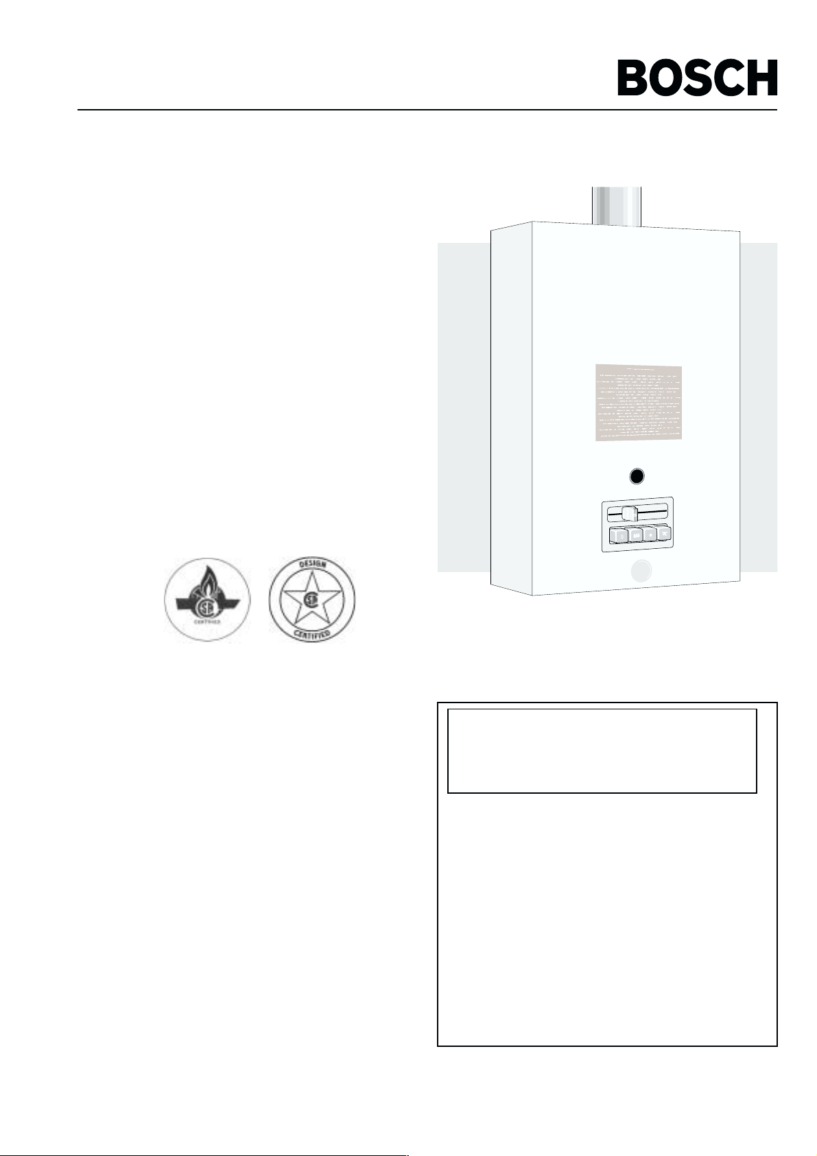
The Bosch instantaneous water heater is a high efficiency,
space saving answer to your water heating needs. All Bosch
instantaneous water heaters heat water only as required;
noenergy is lost maintaining a large voluma of water at
elevated temperatures as in tanktype storage water heaters.
Suitable for heating potable water. Certified for space heating
in combination with potable water only. Not certified for
heating only.
READ INSTRUCTIONS CAREFULLY BEFORE INSTALLING
NOTICE TO INSTALLER: Please leave this manual
with the owner or affix adjacent to appliance.
ASTRAVAN DISTRIBUTORS, LTD.
123 Charles Street
6 720 601 783 CA (03.11) AL
North Vancouver, B.C. V7H 1S1
Phone Canada: (604) 929-5488
Phone USA: (206) 860-8448
Web Site: www.astravan.com
WARNING: If the information in this manual is
not followed exactly, a fire or explosion may
result causing property damage, personal injury
or death.
−−
− Do not store or use gasoline or other flammable
−−
vapors and liquids in the vicinity of this or any other
appliance.
−−
− WHAT TO DO IF YOU SMELL GAS
−−
••
• Do not try to light any appliance.
••
••
• Do not touch any electrical switch; do not use
••
any phone in your building.
••
• Immediately call your gas supplier from a
••
neighbor’s phone. Follow the gas supplier’s
instructions.
••
• If you cannot reach your gas supplier, call the
••
fire department.
−−
− Installation and service must be performed by a
−−
qualified installer agency or the gas supplier.
Note: In case of problems please contact your salesman or installer
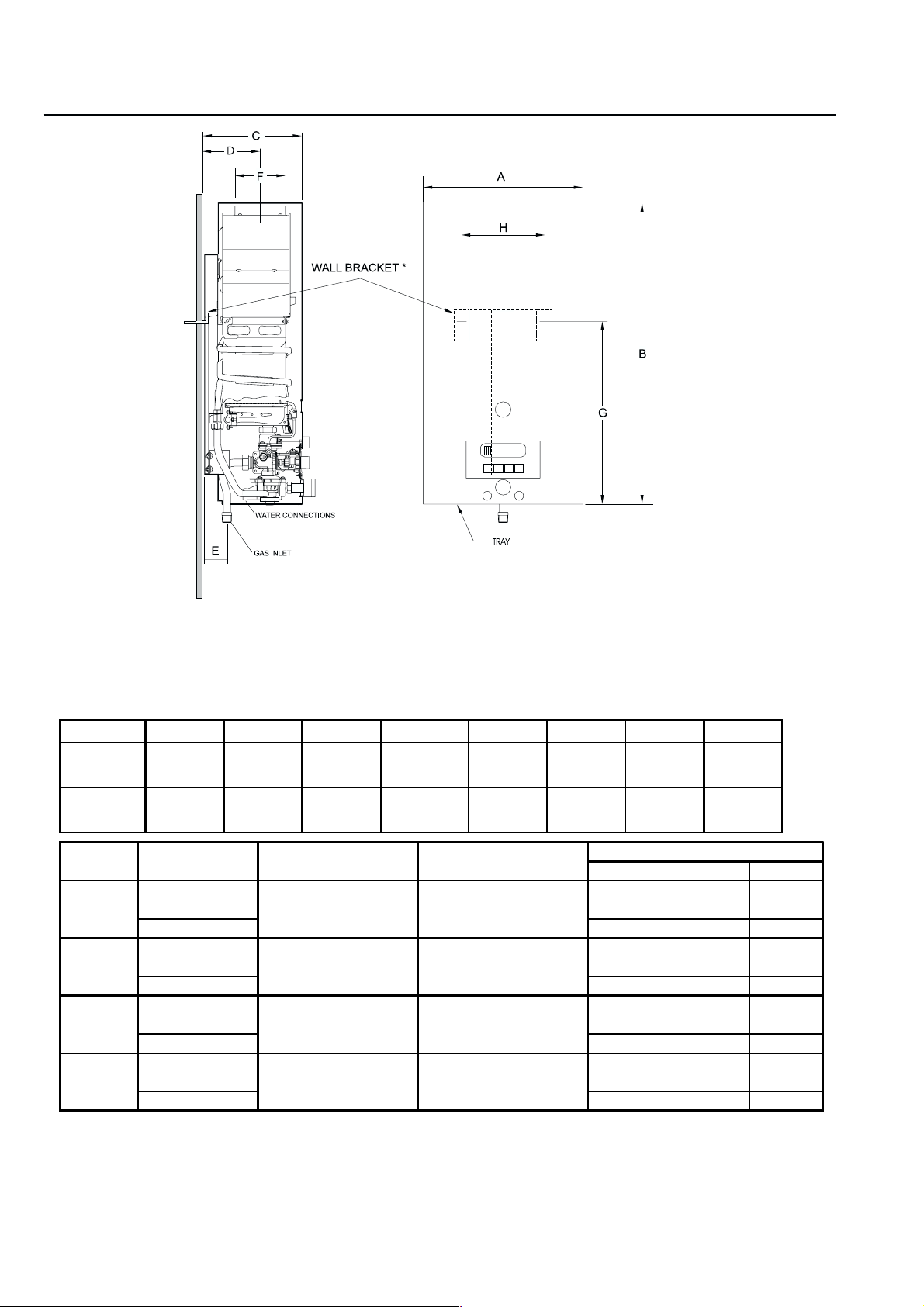
DIMENSIONS
Figure 1
Maximum hydrostatic water pressure – 1.03 Mpa (150 p.s.i.)
Maximum recommend working pressure – 0.69 Mpa (100 p.s.i.)
Minimum working pressure – 0.0138 Mpa (2 p.s.i.) at 2 Litres/min. (0.5 U.S. Gallons/min) free discharge
Minimum recommended inlet water pressure for use with showers 30 p.s.i.g.
Dimensions in Milimetres (inches)
Model A B C D E F G H
W325
W400
Model Type of gas Altitude Input
W325
W325
W400
W400
400 755 250 155 85 130 410 320
17 1/4" 29 3/4" 9 3/4" 6" 3 1/4" 5" 16 1/8" 12 5/8"
440 770 250 155 85 130 410 320
17 1/4" 30 1/4" 9 3/4" 6" 3 1/4" 5" 16 1/8" 12 5/8"
Main Burner orifices
Size, mm Qt.
Natural
Propane 0.79 diam. 14
Natural
Propane 0.79 diam. 14
Natural
Propane 0.82 diam. 16
Natural
Propane 0.82 diam. 16
standard 29.30kW (100,000Btu/hr) 1.25 diam. 14
(0 - 2,000 ft.) 27.83 kW (95,000Btu/hr)
high** 26.37kW (90,000Btu/hr) 1.25 diam. 14
(2,000 - 4,500 ft.) 25.05 kW (85,000Btu/hr)
standard 34.28 kW 1.25 diam. 16
(0 - 2,000 ft.) (117,000Btu/hr)
high** 30.85 kW 1.25 diam. 16
(2,000 - 4,500 ft.) ( 105,000Btu/hr)
* The wall bracket is only required for the WR 325 K … when mounted directly to combustible construction. The WR
400 K… T2 may be mounted directly to combustible construction.
** The high altitude ratings listed are Canadian Gas Association high altitude ratings and are only valid in Canada. In the
U.S., the National Fuel Gas Code, ANSI Z223.1/NFPA 54, recommends for high altitude installations above 2,000 feet,
that the input rate be reduced 4% for each 1,000 feet above sea level. – See page 8.
2

FORWARD
This design complies with CAN1-4.3-77 and ANS1Z21.10.3b
1994 as an instantaneous gas water heater. In addition the
unit complies with CAN1-2.17-M80 for use at high altitude,
2.000-4.500 feet above sea level.
Installation, operation and maintenance information is
provided in this manual. Installation and operation instrution
should be thoroughly reviewed before proceeding with
installation of the BOSCH instantaneous gas water heater.
The BOSCH instantaneous gas water heater is designedto
operate on natural or propane gas; however, make sure
that gas onwhich heater is to operate is to operate is the
same as specified on the heater’s model/rating plate.
In addition to these instructions, the water heater shall be
installed in accordance with CAN1-B149 Installation Code
(in Canada) or ANSI Z223-1/NFFA 54 National fuel Gas
Code (in U.S.) and/or local installation codes.
These shall be carefully folowed in all cases.
INSTALLATION INSTRUCTIONS
Note: Proper plumbling, venting, gas connections and an
adequate supply of combustion air are required for safe and
reliable operatrion. Ability equivalent to that of a licensed
tradesman in the field involved is required for installation
and/or servicing of these heaters.
AIR REQUIREMENTS
For safe operation ,sufficient air for combustion, ventilation
and dilution of flue gases must be available. An insufficient
supply of air will result in a yellow luminous burner flame,
causing carboning or sooting of the heat exchanger.
LOCATION
Before installation the BOSCH instantaneous gas water
heater consideration must be given to proper location.
Location should be as close to a chimney or gas vent as
practicable, in an area with an adequate air supply and as
centralized with the piping system as possible. The heater
should not not be located in area where it will be subject to
freezing. The heater should be located in an area where
leakage of the heater or its connections will not result in
damage to the area adjacent to the heater or to lower floors
of the structure.
In order to prevent corrosion, make sure that the combustion
air kept free of aggressive substances. Subtances that
especially contribute to corrosion are halogenated
hydrocarbons (e.g. chlorine and fluorine), which are
contained in solvents, paint, adhesives, propellant gases,
various house hold cleaners, etc. Take precautionary
measures as necessary.
If plastic pipes are used , a 1.5 m metal connection must be
provided on the cold and hot sides.
Note: When such loctions cannot be avoided, it is
recommended that a suitable drain pan, adequately
drained, be installed under the water heater. The pan
must not restrict combustion air flow.
In unconfined spaces, in buildings of normal construction,
infiltration normally is adequate to provide air for combustion,
ventilation and dilution of flue gases. However, a confined
space must be provided with two permanent openings to
provide combustion and ventilation air to the appliance. Each
opening shall have a free area of one square inch per 1000
BTU/Hr* of total input rating os all appliances in the
enlosure.One opening shall be within 12 inches of the top
and one within 12 inches of the bottom of the enclosure.
* SPECIAL NOTE
When the W 400 K… T2 is installed in a confined space of
minimum size the openings described above must be
increased to a size of 1 ½ square inches per 1000 BTU/Hr.
In other words, for the W400 K..T2 installed in a minimum
sized confined space the two openings that are to be made
in the enclosure within 12 inches of the top and 12 inches
of the bottom must each have a minimum free area of, (11/
2”) x (117) = 175.5 square inches.
3
For either confined or unconfined space in a building of
tight construction with inadequate infiltration, air must be
drawn from the outdoors or from spaces that freely
communicate the outdoors. Two permanent openings located
as indicated above are to be provided as follows:
1. When communicating with outdoor directly, or by means
of vertical ducts, each opening shall have a free area
of not less than one square inch per 4000 BTU/Hr of
total input of all appliances in the space.
2. When communicating with outdoors by means of
horizontal ducts, each opening shall have a free area of
not less than one square inch per 2000 BTU/Hr of
total input of all appliances in the space.
For detailed reqirements see
- in Canada, CAN 1-B 149 Installation Codes
- in U.S., ANSI Z223.1/NFPA 54 National Fuel Gas Code.
MOUTING
The W 325 K.. and W 400 K.. are design certified for
mounting to a wall. A wall bracket, see figure 1 is provided
with the W 325 K.. and must be used when the heater
mounted on a combustible wall. Heaters may not be installed
directly on a carpeted wall.
The heater, or the wall bracket, must be mounted to the wall
using appropriate anchoring materials.
WARNING
Failure to use the wall bracket with the W 325 K… when
installing the unit on combustible construction will cause
an unsafe condition and possible fire. In addition, failure to
use the wall bracket when installing the W 325 K… on
combustible construction will be in violation of A.G.A. and
C.G.A. certification of the unit.
WARNING
1. Flammable materials, gasoline, pressurized containers,
or any other items or articles that are potentially fire
hazards must never be placed on or adjacant to the
heater. The appliance area must be kept free of all
combustible materials, gasoline and other flammable
vapors and liquids.
2. Do not obstruct the flow of combuston and ventilation
air to the appliance.
CLEARENCE
In Canada
The W 325 and the W 400 are design certified for installation
on a combustible wall (for the W 325 the wall bracket
supplied with the unit must be used for mounting to
combustible construction), and for installation in an alcove
or closet with minimum clearances to 0 mm from back, 102
mm (4 inches) from sides, 305 mm (12 inches) from top and
bottom, and 102 mm (4 inches) from front. A minimum of
305 mm (12 inches) shall be allowed for maintenance of
serviceable parts.
Clearence from vent is dependant upon the clearence rating
of the venting material used; that is, type B-1 vent is approved
for 1 inch clearence, B-2 vent for 2 inch, etc.
In United States
The W 325 and the W 400 are design certified for installation
on a combustible wall (for the W 325 the wall bracket
supplied with the unit must be used for mounting to
combustible construction), and for installation in an alcove
with minimum clearences to combustible construction of 0
mm from back, 102 mm (4 inches) from sides, 305 mm (12
inches) from top and bottom. In addition, the WR 325 has
also been design certified for closet installation with minimum
clearences to combustible construction of 0 mm from back,
102 mm (4 inches ) from sides, 305 mm (12 inches) from
top and bottom, and 102 (4 inches) from front. A minimum
of 305 mm (12 inches) shall be allowed for maintenance of
serviceable parts.Clearence from vent is dependent upon
the clearence rating of the venting material used, that is,
type B-1 vent is approved for 1 inch clearence, B-2 vent for
2 inch, etc.
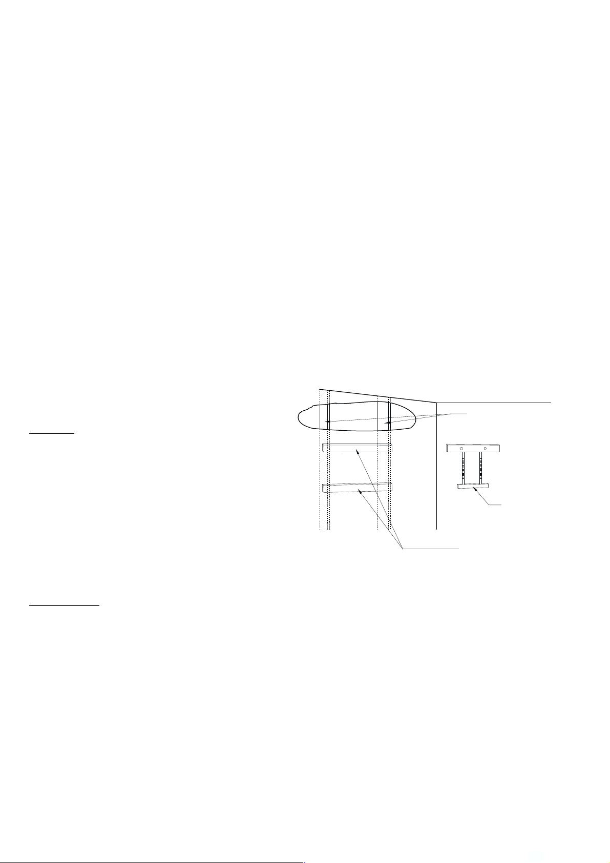
Note: If wall is a stud wall sheethed with plasterboard it is
recommended that support board(s), either 1 x 4’s or ½
(minimum) plywood first be attached across a pair of
studs and then heater, in the case of the W 400 K…,
or the wall bracket, in the case of the W 325 K…, be
attached to the support boards. See figure 2.
WALL STUDS
WALL
BRACKET
1” X 4” SUPPORT
Figure 2
BOARDS
Expansion and contraction of piping due to changing water
temperature in pipes imparts movement to heater which, if
mounted directly to a brittle, friable board such as
plasterboard can cause failure of mounting.
4
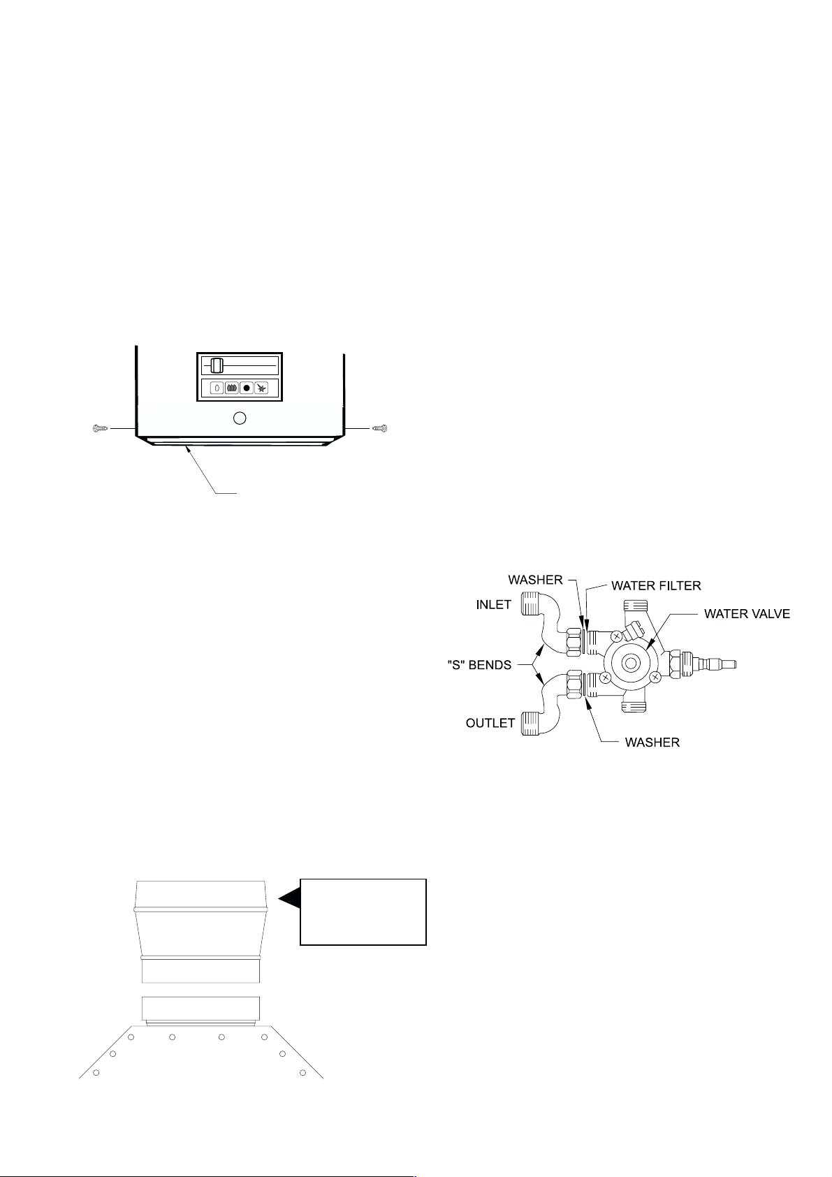
DRIP TRAY
If the water heater is being mounted above a floor of
combustible construction, the drip tray ( shipped loose in
the water heater) must be attached to the bottom of front
cover of the water heater at time of installation. The drip
tray should be attached to the front cover, using screws
provided, as shown in figure 3.
Failure to use drip tray when installing unit above a floor of
combustible construction will cause an unsafe condition and
possible fire and will be in violation of A.G.A. and C.G.A.
sertification of the unit.
DRIP TRAY
For high altitude use the adaptor must be installed as shown
in figure 4, without alternation, before connecting the six
inch flue to the unit. The adaptor must be secured to the
draft diverter outlet with a minimum of two screws.
Also, in Canada, the gas pressure regulator supplied with
the water heater is factory preset to deliver gas to the water
at the proper pressure settting for high altitude operation,
see PRESSURE REGULATION section of this manual.
WARNING
Failure to increase vent size on W 400 to six inches and/or
to assure that manifold pressure is set to proper value listed
on rating plate for applications at altitudes in range 2,000
to 4,500 ft. above sea level will cause unsafe venting,
asphyxiation, and voids C.G.A. certification.
WATER CONNECTIONS
The W series instantaneous water heatrs are provided with
two S-bend water connectors/adaptors that must be
connected to inlet and oulet and outlet connections on water
valve assembly, see figure 1 and figure 5 below.
Figure 3
VENTING
The BOSCH instantaneous water heaters have builtin draft
diverters and are designed for indoor installation only. The
draft diverter outlet must be connected to a clear,
unobstructed vent of the same size, or lerger, refer to:
- In Canada, CAN1-B149 Installation Code for detailed
requirements.
- In U.S.A., ANSI Z223.1/NFPA 54 – National Fuel Gas
Code for detailed requirements.
The flue connection for both the W 325 K… and W 400
K… is 130 mm (5 inches); however, in Canada for
installations at high altitude (2,000-4,500 ft. above see level)
a six inch (6”) flue is required for the W 400 K.
5” x 6” adaptor used
on high altitude model
W 400 only
Water valve and S-bends, top view
Figure 5
The purpose of the S-bend water connectors/adaptors is to
provide threaded water connections that meet standards
used in North America, ANSI Standard Taper Pipe Thread
(1/2” NPT). The cold water supply should be connected to
S-bend attached to inlet of water valve and hot water
connection should be made to S-bend attached to outlet of
water valve.
Figure 4
Note: A shut-off valve should be placed in the cold water
supply line to the heater to facilitate servicing the
heater.
5
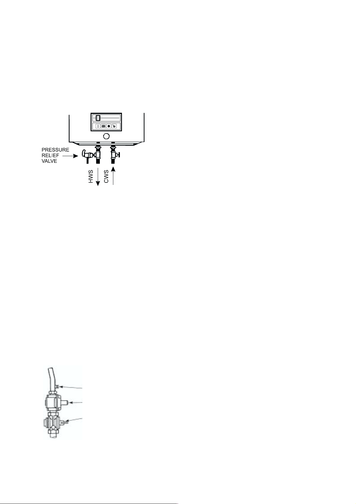
RELIEF VALVE
The listed pressure relief valve supplied must be installed
near the hot water outlet at time of installation of the heater.
No valve is to be placed between the relief valve and the
heater. A line must be connected to the relief valve to direct
discharge to a safe location. Do not install reducing coupling
or any other restriction in the discharge line must be installed
so as to allow complete drainage of the valve and the line.
See figure 6.
Figure 6
GAS CONNECTIONS
Before connecting the gas supply to the heater check
heater’s model/rating plate to make sure that gas on which
heater is to operate is the same as specified on the model/
rating plate.
The W 400 K and the W 325 K instantaneous gas water
heaters are supplied with a gas pressure regulator that must
be installed on the heater before attaching the gas supply
line, see figure 7. Failure to install the pressure regulator, or
the failure to install it in the sequence shown in figure 7 will
be of A.G.A. and C.G.A. certification of the unit.
BOSCH water heaters are shipped from the factory with
the gas pressure regulators preset for tte gas shown on the
rating plate to the correct pressure:
- in Canada, for high altitude operation;
- in U.S., for standard altitude operation unless specially
marked as a high altiude unit.
Check to make sure that the gas listed on the rating plate is
same as gas listed on the pressure regulator.
See PRESSURE REGULATION of this manual for
information regarding gas pressure settings.
Note: Before attaching the gas supply line, be sure that all
gas pipe is clean on the inside. To trap any dirt or
foreign material in the gas suplly line, a drip leg must
be incorporated in the piping. The drip leg must be
readily accessible and not subject to freezing
conditions. Install in accordance with
recommendations of serving gas supplier.
Joint compounds (pipe dope) shall be applied sparingly and
only to the male threads of pipe joints. Do not apply
compound to the first two threads. The joint compound used
must be resistant to the action of liquified petroleum gases.
Before placing water heater in operation check for gas
leakage. Soap and water solution, or other material
acceptable for this purpose, shall be used in locating gas
leaks. Matches, candles, lighters, or other ignition sources
shall not be used for this purpose.
WARNING
The heater and its individual shutoff valve must be
disconnected from the gas supply piping system during any
pressure testing of that system at test pressure in excess of
3,45 kPa (1/2 psig).
The water heater must be isolated from the gas supply piping
system by closing its individual manuaql shutoff valve during
any pressure testing of the gas supply piping system at test
pressures equal to or less than 3.45 kPa (1/2 psig).
Figure 7
6
PRESSURE TAP
PRESSURE REGULATOR
MANUAL GAS VALVE
The water heater, including the pressure regulator and
manual valve provided with it, must not be operated at gas
supply pressures in excess of 3.45 kPa (1/2 psig). If
overpressure has occurred such as through improper testing
of the gas lines or emergency malfunction of the supply, the
gas valve and regulator must be checked for safe operation.
Make sure that the outside vent valves are protected against
blockage. These are part of the gas supply system, not the
water heater.Vent blockage may occur during ice storms.
OPERATING INSTRUTIONS
WARNING
If the water has been damaged or exposed to fire or sooting
or if any part has been underwater do not use. Immediately
call a qualified service technician to inspect the appliance
and to replace any part of the control system and any gas
control which has been underwater and to clean the heat
exchanger assembly and water valve.
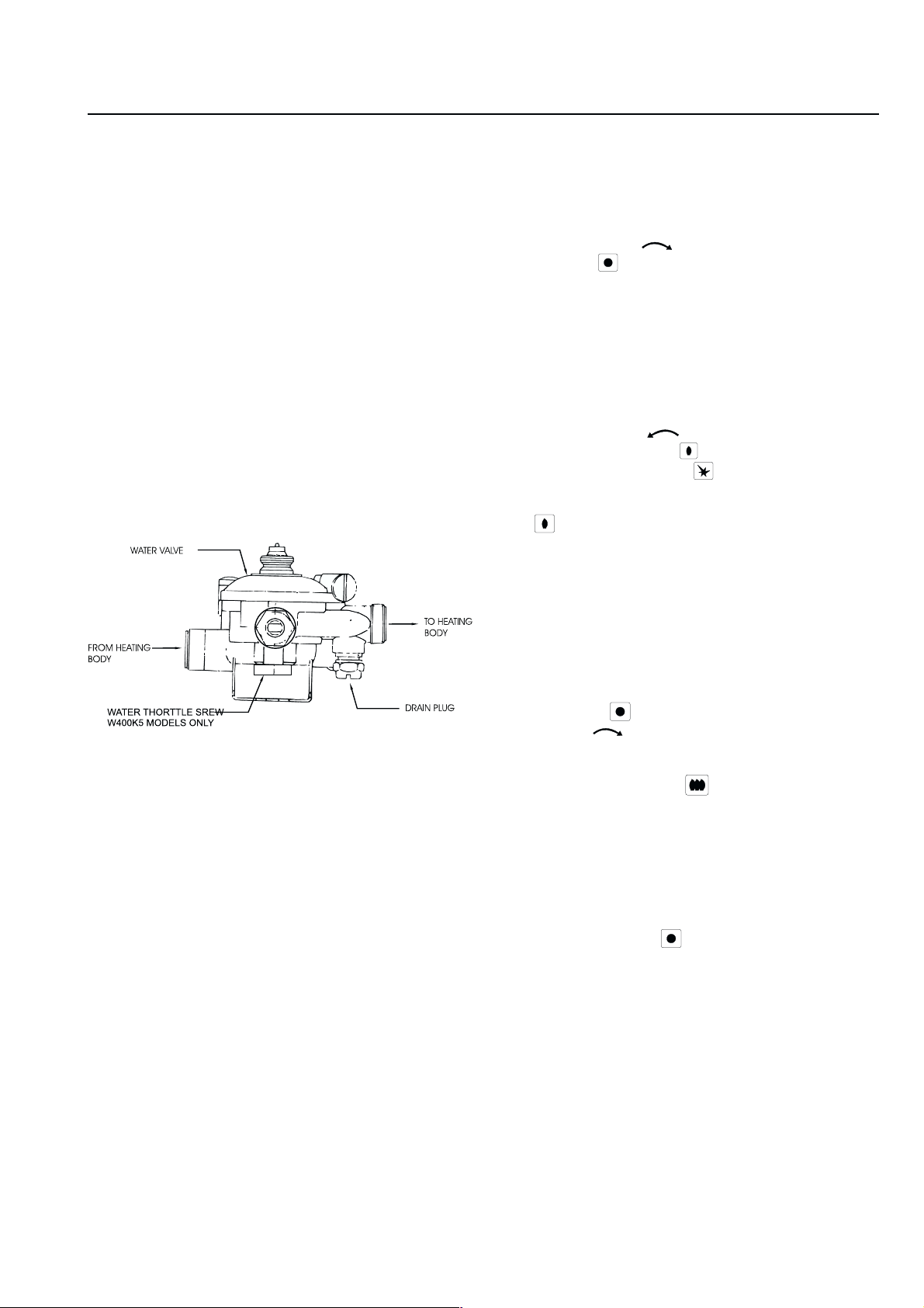
FILLING
Before proceeding with operation of the water heater make
sure that system is filled with water.
- Make sure drain is closed, see figure 8, below.
- Open a nearby hot water faucet to permit the water to
fill the heater and piping.
- Close the hot water faucet after the water flows freely
and all air has escaped from system.
- The water heater is now ready to be lit.
Figure 8
LIGHTING INSTRUCTIONS
1. STOP! Read the safety information, first section of the
Lighting Instruction Plate on the cover.
2. The main manual gas valve must be closed (turn valve
handle clockwise ) and the gas valve OFF button
depressed . See figure 9.
3. Wait five (5) minutes to clear out any gas. If you then
smell gas, STOP! Follow “B” in the safety information
given above on this plate. If you don’t smell gas, go to
next step.
4. The pilot burner is located behind the peephole located
in the front center of the jacket directlybelow this
instrution plate.
5. Open main manual gas valve by turning valve handle
counterclockwise .
6. Depress PILOT button and light pilot by pushing
PILOT IGNITER button . This may have to be
repeated.
7. Observe pilot flame though peephole. The PILOT button
- should be held down at least 10 seconds with
pilot burning. When the PILOT button is released the
pilot should continue to burn.
- If the PILOT button does not pop up when released
stop and immediately call your service technician or
gas supplier.
- If the pilot will not stay repeat lighting procedure steps
1 through 8.
- If the pilot will not stay lit after several tries, depress the
OFF button , turn the manual gas valve handle
clockwise to OFF position and call your service
technician or gas supplier.
SERVICE HINT
The strainer (screen) in the water valve, located in the inlet
of the water valve, may require occasional cleaning due to
foreign material in the water supply. This will restrict the
flow of may affect heater operation and prolong filling time.
To inspect the strainer close the cold water supply valve
ahead of the heater, disconnect S-bend from inlet of water
valve, and remove strainer from inlet. Clean if required,
replace strainer in inlet to water valve, reconnect S-bend
and turn on water supply.
Light the water heater in accordance with the instructions
on the Lighting and Operating Plate on the water heater.
For your convenience, the instructions are repeated below.
8. Depress the ON button . The heater will now fire
when water is drawn at arate greater than the threshold
flow rate (see manual)*.
Note: If main burner should fail to ignite make sure pilot is
burning. If not repeat lighting procedure steps 1 through 8.
TO TURN OFF GAS TO APPLIANCE
1. Depress OFF buton and close the main gas valve
by turning handle clockwise to OFF position. See figure
9.
*see Water Flow Selector section.
7
PRESSURE REGULATION
The pressure regulator supplied with the water heater is
adjusted to operate on the gas specified on the rating plate,
and:
- in Canada, is factory preset to deliver gas at the high
altitude pressure setting listed on the rating plate and
as shown below.
- In the U.S., is factory preset to deliver gas at the standard
altitude setting listed on the rating plate and as shown
below.
The pressure setting of the gas pressure regulator should
be checked at installation to assure that the setting is correct
for the gas being used and the altitude at which the
appliance is installed. See rating plate on the unit, or the
chart below for proper settings.
In Canada, for a heater being installed at standard altitude
(o-2,000 ft. elevation) the manifold pressure should be reset
at installation to value shown on the rating plate, or chart
below, for standard altitude.
The gas pressures specified below refer to flow pressure
taken at the pressure tap in the gas inlet pipe (just above
pressure regulator), figure 9, while the heater is operating
at full input.
Appliance Regulator Pressure Setting
Model Type of Gas
W325
W325
W400
W400
natural 1.36 5.5 standard
propane 2.61 10.5 (0-2,000 ft.)
natural 1.09 4.4 high *
propane 2.11 8.5 (2,000 - 4,500 ft.)
natural 1.41 5.7 standard
propane 2.61 10.5 (0-2,000 ft.)
natural 1.14 4.6 high *
propane 2.09 8.4 (2,000 - 4,500 ft.)
*Note: The high altitude ratings listed are Canadian Gas
Association high altitude ratings for the appliances and are
only valid in Canada. In the U.S. the National Fuel Gas
Code, ANSI Z223.1/NFPA 54, recommends for high altitude
installations, above 2000 feet, that the input rate be reduced
4% for each 1,000 Feet above sea level.
Pressure
kPa Inches, W.C.
Altitude
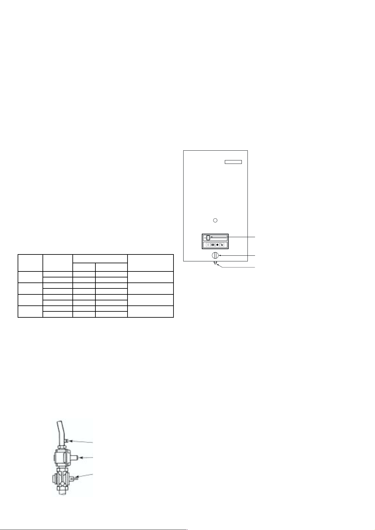
TEMPERATURE REGULATION
I W325K and W400K Models only
For domestic purposes the water flow selector should be
turned clockwise to stop and the gas control slide slid to
right hand stop and remain in those positions.
See figure 10.
Should overheating occur or the gas supply fail to shut
off, turn off the manual gas control valve to the appliance
and have the heater checked by a qualified serviceman to
determine the reason for te malfunction.
GAS CONTROL SLIDE
WATER FLOW SELECTOR KNOB
W325K AND W400K ONLY
WATER THROTTLE SCREW
Figure 10
WATER FLOW SELECTION
With the water flow selector turned clockwise to the stop,
the heater’s water valve will regulate the flow rate through
the heater permitting a maximum flow rate of:
- 5.8 L/Min. (1.5 U.S. Gal./min.), for W325
- 6.8 L/Min. (1.8 U.S. Gal./min.), for W400
W400K5 MODEL ONLY
Your appliance dealer and/or your local gas supplier should
be consulted in regard to any high altitude installation. If
field adjustment is required it should be performed by a
qualified serciveman experienced in such work.
PRESSURE TAP
PRESSURE REGULATOR
MANUAL GAS VALVE IN OFF
POSITION
Figure 9
8
This setting permits a person at a remote location to control
the water temperature by mixing more or less cold water
with the hot water supplied by the heater.

The water flow selector regulates the hot water output by
1
(
adjustng the flow rate of the water through the heater. Below
you will find listed the maximum that can be selected by
adjusting the water flow selector and the minimum flow rate
for main burner operation.
Also listed are the temperature rises that would be expected,
at flow rates indicated, when the heater is firing at full input.
WATER FLOW ADJUSTMENT RATE ALL
MODELS
Model
W 325
W 400
Maximum Flow Rate
(counter-clockwise to stop)
3 L/min.
3.4 U.S. Gal./min.) Temp.
Rise 25° C (45° F)
15 L/m in. (4.0
U.S. Gal./min.) Temp.
Rise 25° C (45° F)
Minimum Flow Rate
(clockwise to stop)
5.8 L/min. (1.5
U.S. Gal./min.) Temp.
Rise 55° C (100° F)
6.8 L/min. (1.8
U.S. Gal./min.) Temp.
Rise 55° C (100° F)
*Note: If flow rate through the heater is less than the minimum
flow rate shown for the heater the main burner will not fire.
The minimum flow rate is the “THERSHOLD FLOW RATE”
referred to in the lighting instructions.
II W400 K5 Models only
These models do not have a manual flow selector knob.
Flow can be regulated using the water throttle screw on the
bottom of the water control valve (see fig.8).
Because this model is usually always used for full flow
applications such as recirculation to storage, pressure
washers, boosters, etc., this water throttle screw somes from
the factory srewed in (clockwise) to maximum flow position
to give flows and temperature indicated above.
GAS CONTROL SLIDE
With the gas control slide at the right hand stop the heater
will fire at its full rated input when water is drawn at a rate
that will cause the gas valve to open fully. The gas control
slide will restrict the input down to approximately 50% of
full rated input when adjusted to the left hand stop.
HIGH TEMPERATURE LIMIT SWITCH
The BOSCH W series instantaneous gas water heaters
are equipped with a high temperature switch with a set point
of approx. 90° C ( 194° F). If the water temperature at the
point exceeds the set point the switch will open, interrupting
the safety circuit and stopping gas flow to the pilot and
main burner.
Outage as a result of high limit operation indicates that the
heater is not functioning properly. The heater should be
checked by a qualifed serviceman and reason for
malfunction corrected. To relight pilot follow instructions
provided on unit.
9
 Loading...