

Bosch W 135 K..B, W 275 1 K.B., W 400-1K..B, W 350 1 K.B. Installation, Servicing And User Instructions Manual
Page 1
For your safety
If you smell gas:
- Turn off gas isolating valve;
- Open windows to increase air circulation;
- Do not operate any electrical switches;
- Do not use the telephone on the premises;
- Call an authorised technician or the local gas authority
immediately.
Installation and servicing should only be performed
by authorised personnel.
Regular maintenance is recommended to ensure correct
and safe performance.
Do not store or use inflammable liquids or materials near
the appliance.
If the appliance is installed in a position likely to be affected
by frost, isolate gas and water supplies, remove batteries
and drain. If problems occur call an authorised technician
immediately.
The installer should explain to the customer how the
appliance functions and how to operate it. A copy of these
instructions must be made available to him.
W 135 K.B..
W 275 - 1 K.B..
W 350 - 1 K.B..
W 400 - 1 K.B..
Gas Fired Instantaneous
Water Heaters
Installation, Servicing and User Instructions
With electronic ignition and
ionisation probe safety
system
6 720 605 351 PT 1999.11
Page 2
2
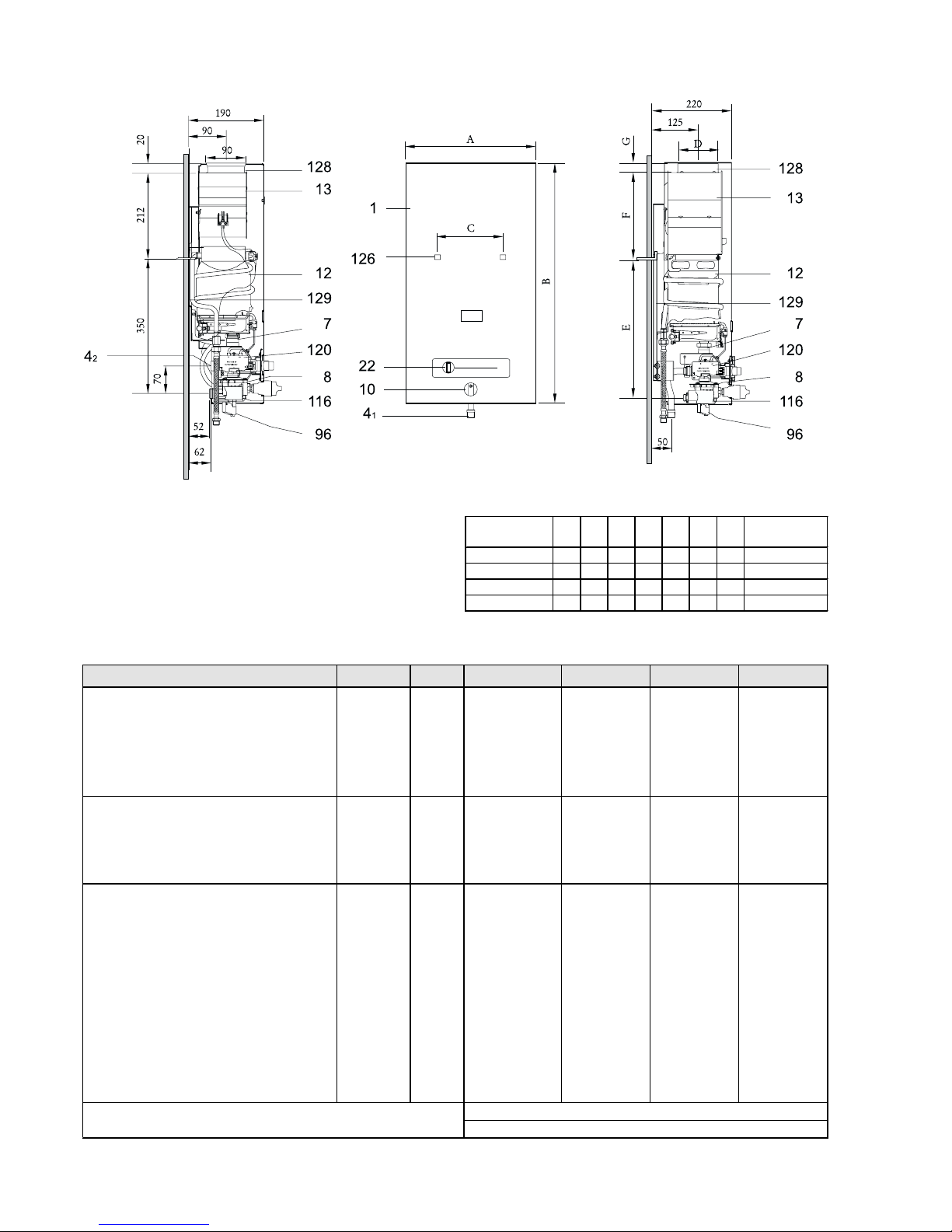
1.1 Dimensions
1 - Front cover
41 - Gas inlet
42 - Gas inlet (W135... Ø 3/4")
7 - Gas valve assembly
8 - Water valve assembly
10 - Temperature selector
12 - Heat exchanger
13 - Chimney with draught
diverter
Fig. 1
D663_014
22 - Output slide control
120 - Ignition unit
116 - Battery box
96 - Micro-switch
126 - Position of back
panel mounting slots
128 - Flue pipe connection
129 - Back panel
1.2 Technical Data
1. Main Features and Technical Data
*Hi 15°C - 1013 mbar - dry: Butane = 45.72 MJ/kg (12,7kWh/kg) - Propane = 46.44 MJ/kg (12,9 kWh/kg)
** Even with the effects of water dilation, the water pressure in the appliance shall not exceed this value.
W 135 K..B
W 275/350/400 K..B
Dimensions
(mm)
ABCDEFG
W 135 K..B..
270 610 138 ---- ---- ---- ---- ø3/4"
W 275-1K..B..
360 680 228 110 423 227 25 ø3/4"
W 350-1K..B.. 400 755 228 132 460 233 30 ø3/4"
W 400-1K..B..
460 755 334 132 512 182 30 ø3/4"
Gas connection
Ø
Appliance Ratings Symbols Units W 135..B W 275-1..B W 350-1..B W 400-1..B
Nominal useful output
P
n
kW 9.4 19.2 24.4 27,9
Minimum useful input (based on net c.v.)
P
min
kW 4.7 9.6 12.2 14
Manual useful output range kW 4.7-9.4 9.6-19.2 12.2-24.4 14-27.9
Nominal heat input
Q
n
kW 11.2 21.8 27.9 32.1
Minimum heat input
Q
min
kW 5.6 10.9 14 16.1
Gas inlet pressure
LP gas (Butane/Propane)* - 3+ G30/31 mbar 28/37 28/37 28/37 28/37
Gas consumption
LP gases - (Butane/ Propane)* kg/h 0.85 1.7 2.2 2.5
Water data **
Maximum inlet water pres sure
p
w
bar 12 12 12 12
Water flow selector
right
Min. water flow l/min. 2.5 5 5.9 7.3
Temperature rise °C55 555555
Min. inlet water pressure
p
wmin
bar 0.15 0.15 0.2 0.2
Water flow selector
left
Min. water flow l/min 5.4 11 14 16
Temperature rise °C25 252525
Min. inlet water pressure bar 0.6 0.5 0.8 1.2
CATEGORY
II
2H3+
TYPE
B
11BS
Page 3

3
2. Installation Requirements
Gas Safety (Installation and Use) Regulations:
October 1994
All gas appliances must be installed by a competent person
in accordance with the above regulations. Failure to install
appliances correctly could lead to prosecution.
2.1 Location
The appliance should be installed in a frost-free, wellventilated room and connected to a flue.
2.2 Water Connection
It is advisable to flush all water pipes before installing your
gas appliance, purging them of sand and other particles
which could later affect the heater's performance.
Make sure the water valve is fitted with a water filter.
Regular cleaning of the water filter should be carried out.
Identify and mark cold (right) and hot water (left) pipes to
avoid wrong connections.
Connect water pipes to appliance using correct fittings.
2.3 Gas Connection
Make sure that your water heater model is compatible with
the type of gas supplied.
A gas isolating valve must be provided near the appliance.
Verify the gas supply pressure - compare with the values in
chapter "Technical Data", pt. 1.2.
2.4 Flue Pipe Connection
The appliance must be connected to a flue pipe, no smaller
than the appliance outlet, ensuring a good seal.
The flue pipe can be made of galvanised steel, aluminium
or stainless steel.
2.5 Air supply
The room in which an appliance is installed must have a
permanent air vent to outside air or to a room which itself
has direct access to outside air. The minimum effective
area of the air vent(s) must be 23cm2 (W135), 72cm
2
(W275), 99cm2 (W350) or 118cm2 (W400).
Installations in cupboards or compartments require
permanent vents for cooling purposes, one at high level
and one at low level, either direct to outside air or to a
room. Both vents must pass to the same room or be on
the same wall to outside air.
There must be sufficient clearence around the appliance
to allow proper circulation of ventilation air. The minimum
clearances required are 50 mm for the sides and 150 mm
above the appliances front cover.
The minimum free areas required are given below.
After this procedure, whenever a hot water outlet is opened,
automatic ignition will take place by lighting the pilot burner
first, and the main burner about four seconds later. After
some seconds the flame of the pilot burner will die out.
This saves a considerable amount of energy, since the
pilot burner only remains alight during the time it takes to
light the main burner, not as in conventional systems where
it burns permanently.
The gas slide control allows for output variation according
to one's needs. The further to the right you position the
slide the greater the output, but also the greater the
consumption of gas.
In order to optimise energy consumption, adjust slide
position to supply the minimum output required.
When starting up the appliance, the existence of air inside
the gas supply pipework may cause some ignition
difficulties. In that case, open and close the hot water tap
repeatedly to re-start the ignition process, until complete
air purge is obtained.
Fig. 3
Decrease
output
Increase
output
Move slide control
to the right
Fig. 2
additional air inlet may be needed from outside to counter
the effect of the fan.
2.6 Installation
Open gas and water isolating valves and check the
soundness of all connections. Take the two 1,5V batteries
supplied with the appliance and place them correctly in
the battery box (fig. 2).
Refer to BS 6798 and BS 5440:2 for additional information.
A spillage test, as detailed in BS 5440:1, must be carried
out and any remedial action taken to ensure that the
installation meets the standard. The effect of any type of
extract fan in the premises must be considered and an
3. Operating and Servicing
3.1 Operating the Water Heater
The appliance is equipped with automatic electronic
ignition, making it easy to ignite the pilot burner.
Start off by moving the output slide control from the off to
the ignition position.
W135 W275 W350 W400 W135 W275 W350 W400
HIGH LEVEL
(cm
2
)
100.8 196.2 251.1 288.9 50.4 98.1 125.6 144.5
LOW LEVEL
(cm
2
)
201.6 392.4 502.2 577.8 100.8 196.2 251.1 288.9
POSITION OF
AIR VENTS
AIR FROM
THE ROOM
AIR DIRECT
FROM OUTSIDE
Page 4

* To be handled by authorised personnel only.
3.4 Fault Finding
The following table outlines some common problems and their solutions.
3.2 Flue gas safety device
The appliance is equipped with a flue gas safety device. If
the burner extinguishes while in operation, it is likely that
the flue gas safety device has activated. Ventilate the room
and reignite the appliance 10 minutes later. If it happens
again, please contact a professional installer.
The servicing of the flue gas safety device must always
be undertaken by a Corgi registered technician. The flue
gas safety device can never be put out of operation.
3.3 Servicing
Servicing is only to be performed by a Corgi registered
technician. It is recommended that the appliance is fully
serviced every year.
The heat exchanger, main burner, pilot burner and water
valve filter must be thoroughly cleaned.
If necessary, the heat exchanger and connecting pipes
should be de-scaled, and subsequently the soundness of
the water and gas valves checked. A complete check on
all the functions should be carried out.
If some parts have to be replaced, use only original spare
parts supplied by the manufacturer.
Problem Possi ble Cause Solutio n
Appliance does not ignite. Misplaced or worn out batteries. Check position and replace if
necessary.
Slow and difficult ignition of pilot
burner.
Worn out batteries. Replace
Burner extinguishes while in
operation.
Flue gas safety device activated. Ventilate the room and re-ignite the
appliance some minutes later. If it
happens again, contact a Corgi
registered technician.
Insufficient water temperature. Wrong output selected. Check position of water temperature
selector and adjust according to your
output needs.
Insufficient water temperature,
short flame.
Insufficient gas pressure. Check if gas container freezes while in
use. If so, place it in a warmer location.
Check if gas inlet governor is of
appropriate type, and is in good
working condition. Replace if
necessary.*
Dirty/damaged gas filter or burner. Clean gas filter and burner.*
Pilot burner doesn’tsparkwith
water flow.
Unadjusted micro-switch screw. Turn the water off.*
Remove cover cap from lower part of
micro-switch and turn the screw off
until the sparking begins, then turn
further 1 and 1/2 turns.
Insufficient water flow. Insufficient water pressure. Check and adjust.
Dirty taps or mixers. Check and clean.
Blocked water valve. Clean the filter.*
Blocked heating body (scale). Clean and de-scale.*
 Loading...