

Bosch VSS7901/00T & VS79015T Installation And Operational Manual
VSS7901/00T & VS79015T
Installation and Operat ional Manual
Intercom Box
EN
Manuel d•installation et d•opération
Module Interphone
FR
Installations- und Bedieningsanleitung
Intercom Box
DE
Manual de instalación y uso
Caja de Interfono
ES
Installatie- en bedieningshandleiding
Intercom Module
NL
Scatola del Citofono
Scatola interfaccia
IT
Manual de instalação e de instruções
Caixa de Intercomunicador
PT
Skab til Samtaleanæg
Interfacekasser
DA
Installations- och bruksanvisning
Snabbtelefonsenhet
SV
Asennus- ja käyttöohje
Ovipuhelinlaitteella
SU
Installasjons- og bruksanvisning
Intercom Boks
NO
Installation and Operat ional Manual
Intercom Box
GR

7901-79015 | Installation and Operational Manual
TABLE OF CONTENTS
ENGLISH ................................................................ 1
FRANÇAIS ............................................................. 11
DEUTSCH .............................................................. 22
ESPAGÑOL ............................................................ 30
NEDERLANDS ...................................................... 40
ITALIANO .............................................................. 48
PORTUGUÊS ......................................................... 56
DANSK .................................................................... 64
SVENSKA ............................................................... 72
SUOMI .................................................................... 80
NORSK .................................................................... 88
GREEK .................................................................... 96
TECHNICAL SPECIFICATIONS ...................... 104
Bosch Security Systems | 2004-06

EN | 17901-79015 | Installation and Operational Manual
FCC DECLARATION
Installation and Operational ManualENGLISHEN
This device complies with part 15 of the FCC rules.
Operation is subject to the following two conditions:
1. This device may not cause harmful interference.
2. This device must accept any interference received, including
interference that may cause undesired operation.
This equipment has been tested and found to comply with the limits
for a class B digital device, pursuant to Part 15 of the FCC Rules.
These limits are designed to provide reasonable protection against
harmful interference in a residential installation.
This equipment generates, uses and can radiate radio frequency
energy and, if not installed and used in accordance with the
instructions, may cause harmful interference to radio
communications. However, there is no guarantee that interference
will not occur in a particular installation. If this equipment does cause
harmful interference to radio or television reception, which can be
determined by turning the equipment off and on, the user is
encouraged to try to correct the interference by one or more of the
following measures:
• Increase the distance between the equipment and the receiver.
• Connect the equipment to a power socket on a circuit different
from thatto which the receiver is connected.
• Consult the dealer or an experienced radio/TV technician for
help.
Bosch Security Systems | 2004-06

EN | 27901-79015 | Installation and Operational Manual
ELECTRO MAGNETIC COMPATIBILITY (EMC)
Installation and Operational Manual
This equipment complies with European rules for EMC according to
EN55013, EN55020 and EN50082-1.
Operation is subject to the following two conditions:
1. This device may not cause harmful interference.
2. This device must accept any interference received, including
interference that may cause undesired operation.
The equipment conforms with the EMC directive and low-voltage
directive.
This device complies to FCC rules under test conditions that included
use of system cables and connectors between system components. If
you have any problems, contact your dealer.
WARNINGS
Any unauthorized modification to this equipment may cause
violation of the FCC rules resulting in the revocation of the
authorization to operate the equipment.
To prevent fire or shock hazard, do not expose this accessory to rain
or moisture. Do not attempt to disassemble the camera. In order to
prevent shock and fire hazard, do not remove screws or covers.
There are no user-serviceable parts inside.
WARNING:
The exclamation mark within a triangle is intended to alert
the user to the presence of important operating and
maintenance (servicing) instructions in the literature
accompanying the appliance.
Bosch Security Systems | 2004-06

EN | 37901-79015 | Installation and Operational Manual
Intercom Box
TABLE OF CONTENTS
Introduction ...................................................................................... 4
Installation ........................................................................................ 5
Mounting the box
System cable
Doorbell output
External power supply
Volume of the loudspeaker
Settings............................................................................................... 8
Tamper switch active
Operation ........................................................................................ 10
Bosch Security Systems | 2004-06
EN | 47901-79015 | Installation and Operational Manual
INTRODUCTION
Thank you for buying this accessory for your observation system.
>
N
<
E
R
A
A
R
>
N
<
E
R
A
A
R
F
5 5
>
N
<
E
R
A
A
R
F
>
N
<
E
R
A
A
R
F
5
F
5
4
4 4
ColourObservationsystem
talkaction
4
4
4
1
_
menu
view
+ next
auto
2
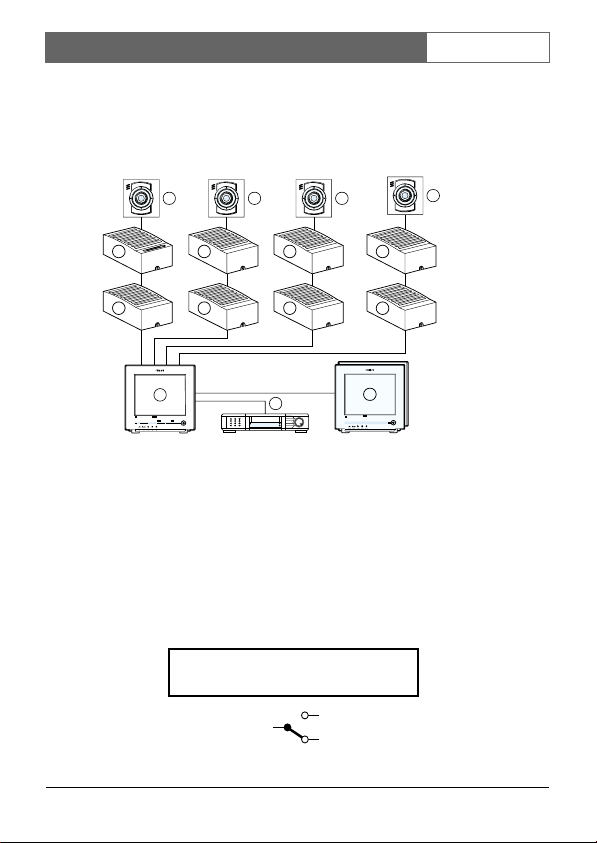
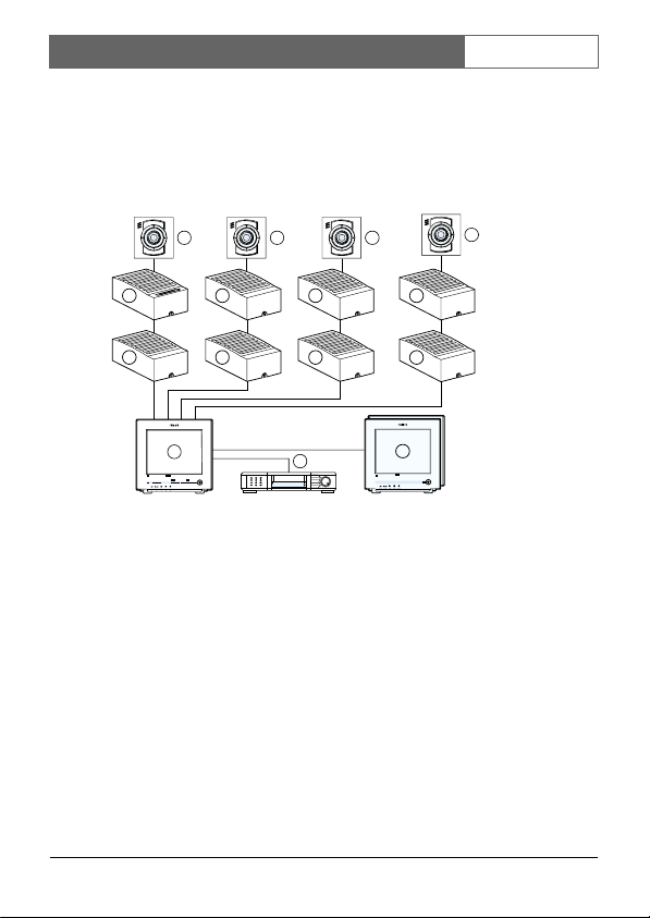
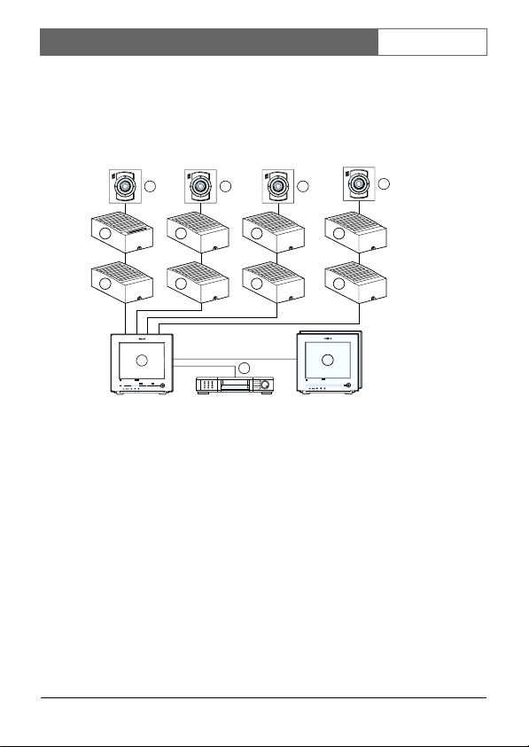
1. System monitor
2. Video recorder (VCR)
3. Slave monitor
4. Accessory boxes (0-2 per cable)
5. System cameras
The following items are included in this kit:
1. Intercom box
1. System cable (5m/15ft)
1. User manual
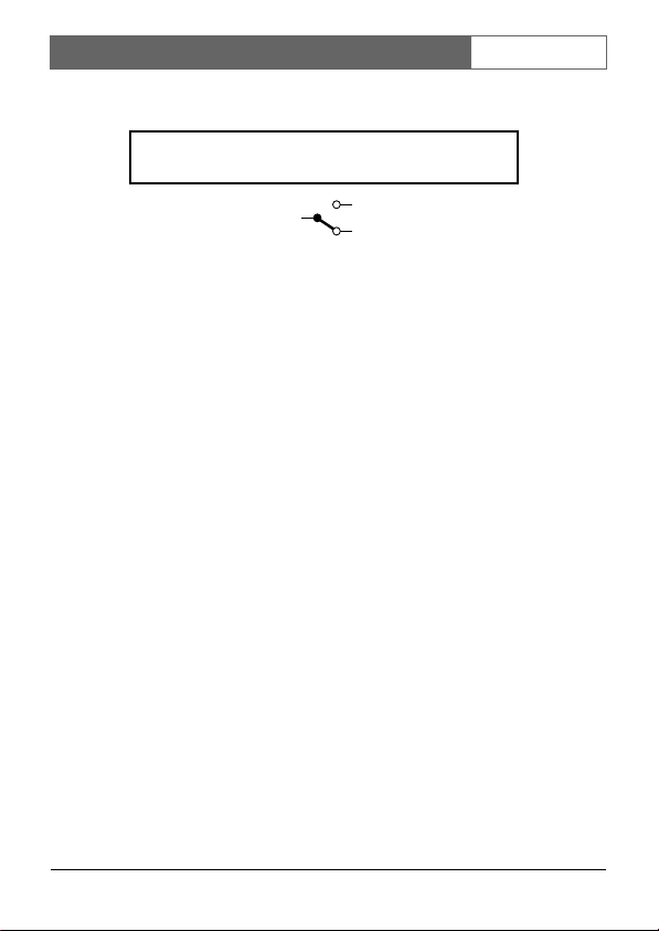
N.O. = Normally Open
N.C. = Normally Closed
common
N.O.
N.C.
Bosch Security Systems | 2004-06
4
4
3
ColourObservationMonitor
ColourObservationMonitor
EN | 57901-79015 | Installation and Operational Manual
The intercom box has a doorbell function. This means that a buzzer
inside the system monitor sounds when someone presses the
intercom’s doorbell button. When the doorbell button is pressed the
monitor switches to the camera input the intercom box is designated
to. The intercom box then allows you and the person near the
intercom box to talk to one another.
INSTALLATION
Remark: When the system configuration is altered, the system
monitor needs to check and memorize the configuration of the
cameras and accessories connected to its inputs.
This is done automatically when the power is switched on. Use the
power switch to switch off. Operating the power save key is not
sufficient. If switching off is impracticable, use the auto install option
of the system monitor's install menu.
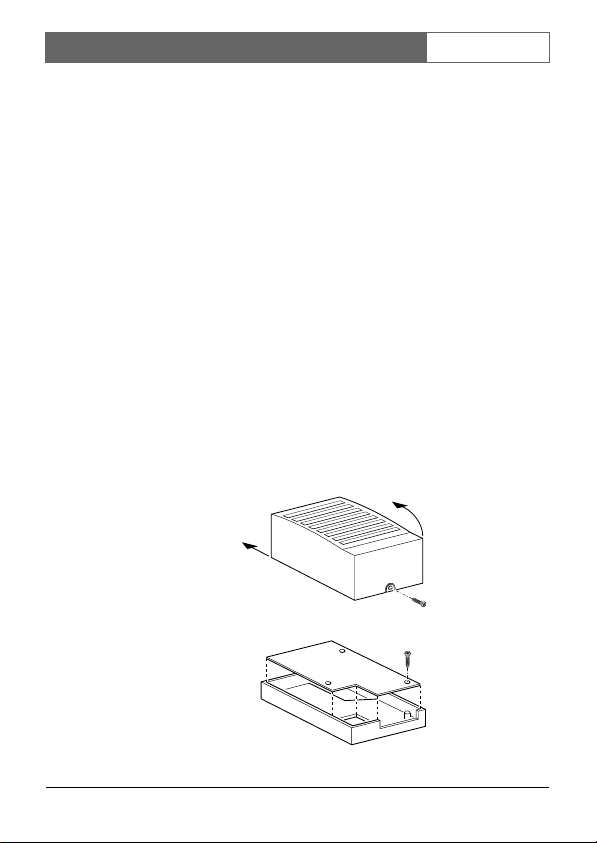
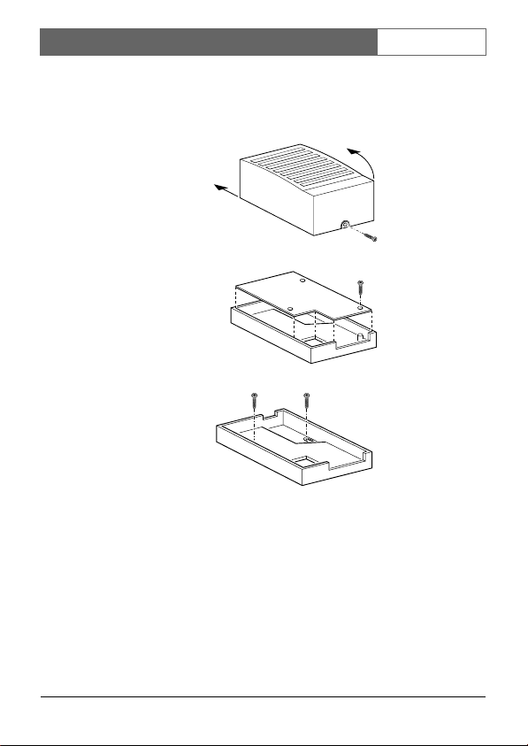
Mounting the box
1. Loosen the screw holding the cover and remove the cover.
2. Remove the circuit board1.
Bosch Security Systems | 2004-06
EN | 67901-79015 | Installation and Operational Manual
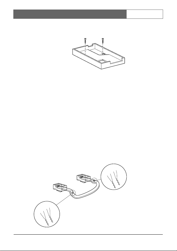
3. Fasten the bottom plate of the box with two screws.
4. Fit the circuit board.
5. Now make the connections as described below.
6. IMPORTANT: Adjust the settings of the circuit board switches to
configure the box according to your system. See section
'settings'.
7. Fit the cover and secure the screw holding it.
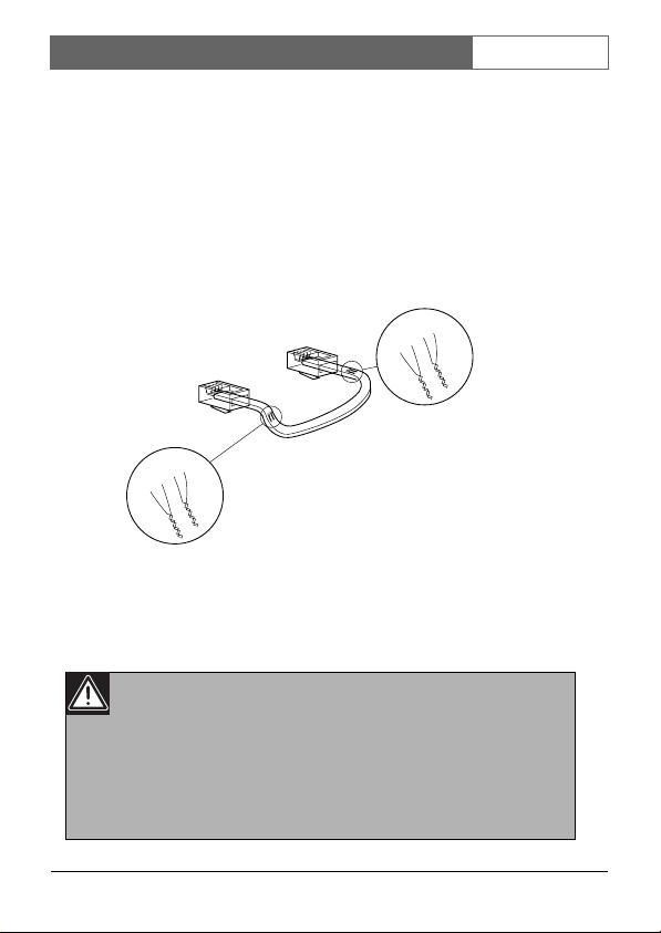
System cable
For the interconnections between the monitor, accessories and
camera a system cable is supplied. For optimum picture and sound
quality you should always use 4-wire dual twisted-pair cable when
extending the connection (max. 300m/900ft). The cable and plugs are
available in the hobby and professional trade. Pay attention that the
connectors are fixed to the cable corresponding to the figure below.
5
4
5
4
3
2
5
4
3
2
3
2
4-5
2-3
5
4
3
2
4-5
2-3
Bosch Security Systems | 2004-06
EN | 77901-79015 | Installation and Operational Manual
If the cable length between monitor and camera exeeds 200m/600ft
after an accessory is inserted in the line a mains power adapter should
be used to power the camera (see accessories).
CAUTION:
The plugs used for the observation system have the same
dimensions as standard telephone plugs.
Never connect the security system with telephone
equipment!
The two sockets for the system cable are interchangeable. One socket
connects the box to the system component previous in the cable, the
other to the next (if any).
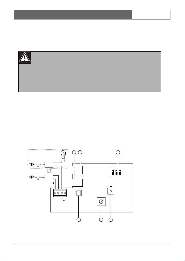
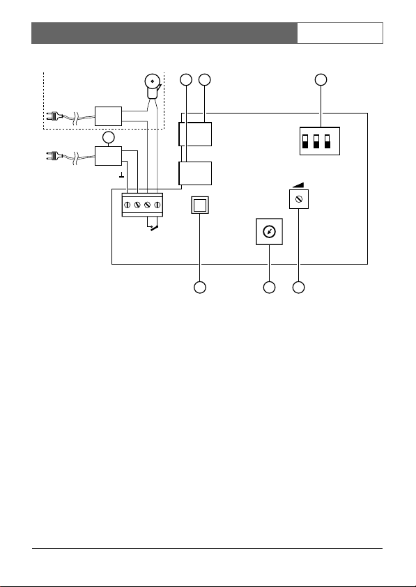
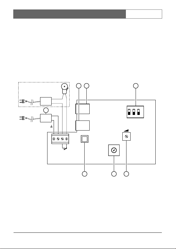
Doorbell output
The figure below shows the screw terminals to which a separate bell
can be connected.
12
7
+24VDC
BELL
BELL
+24V
GND
4
CAMERA #
4
23
1
3
ON
Y
2
ON OFF
123
1 BOX
TAMPER
N LAST
5
6
7
8
9
0
5
1. System-cable input
2. System-cable output
Bosch Security Systems | 2004-06
CL 66610005_508.AI
6
4
EN | 87901-79015 | Installation and Operational Manual
3. Switches 1, 2 & 3
4. Rotary switch
5. Tamper switch
6. Volume preset
External power supply
If at maximum volume setting the loudspeaker volume remains low,
then connect an external power supply (24V
the figure above (7). This is advised when the intercom box is
connected to the system monitor through a long cable.
, 0,5A), as shown in
DC
Volume of the loudspeaker
Adjust the volume of the sound reproduced at the intercom box with
the volume preset (6).
SETTINGS
Four switches - located inside the case, on the circuit board - are used
to configure the circuit according to the system.
• The rotary switch designates the box to a particular camera input.
• The three small slide switches have the following functions:
Switch Off On Description
1 BOX 1 2 number of accessories
2 TAMPER TAMPER OFF tamper-switch override
3 LAST N
Restrictions:
• Maximum one Alarm/Action Box and/or Intercom Box per
camera input.
• Box always designated to camera in line.
Bosch Security Systems | 2004-06
EN | 97901-79015 | Installation and Operational Manual
• Camera is always last in line.
Dedicated settings for Eazeo color systems:
• Switches 1, 2 & 3
• #1 Any position
• #2 OFF tamper switch active, ONoverride tamper switch
(tamper OFF)
• #3 always OFF (N last)
•Rotary switch
Any position (automatically linked to camera in line)
• PIR terminal block (Alarm/Action Box only)
Link NC to - when no PIR is used.
Tamper switch active
On the circuit board a tamper switch secures the box. When opening
the box this switch triggers an alarm on the monitor. To suppress a
continuous alarm message while servicing the system, the tamperswitch override is set in the OFF position.
CAUTION:
Don't forget to reactivate the tamper switch by switching
the override to the TAMPER position!
Bosch Security Systems | 2004-06

EN | 107901-79015 | Installation and Operational Manual
OPERATION
The button on the intercom is used as (door)bell. When pushed, the
buzzer in the monitor (system & slave) sounds. The monitor (system
& slave) switches to the camera input the intercom is designated to.
The automatic camera sequence stops. If you don’t react within 3
minutes - by pushing any button - then the monitor returns to its
previous status (for example, the automatic camera sequence
continues).
The system monitor reproduces the sound received from the
intercom box (plus that of the camera the system switched to, if its
microphone is not switched off). To talk back to your visitor push
talk. The sound received by the system monitor’s microphone is then
reproduced by the intercom.
Bosch Security Systems | 2004-06

FR | 117901-79015 | Manuel d’installation et d’opération
DÉCLARATION FCC
Cet appareil satisfait aux dispositions de la partie 15 des règles FCC
(Federal Communications Commission).
L'utilisation est soumise aux deux conditions suivantes:
1. Cet appareil ne doit pas provoquer d'interférences nuisibles.
2. Cet appareil doit accepter toute interférence reçue, y compris des
interférences susceptibles d'entraîner un fonctionnement
indésirable.
L'équipement a été testé et s'est révélé satisfaire aux limites prévues
pour un appareil numérique de classe B, conformément aux
dispositions de la partie 15 des règles FCC. Ces limites sont conçues
pour fournir une protection correcte contre les interférences nuisibles
dans une installation domestique.
Cet équipement génère, utilise et peut émettre une énergie à radiofréquences et quand il n'est pas installé et utilisé conformément aux
instructions, il peut provoquer des interférences nuisibles pour les
radiocommunications. Néanmoins, il n'est pas garanti que des
interférences ne surviennent pas dans une installation particulière. Si
cet équipement provoque des interférences nuisibles pour la
réception radiophonique ou télévisée, lesquelles peuvent être
déterminées par l'allumage et l'extinction de l'équipement, il est
vivement conseillé à l'utilisateur de tenter de corriger ces
interférences en prenant une ou 1 plusieurs des mesures suivantes:
• Augmenter la distance entre l'équipement et le récepteur
• Brancher l'équipement sur une prise d'alimentation d'un circuit
autre que celui sur lequel est branché le récepteur.
• Faire appel à l'aide du distributeur ou d'un technicien radio/TV
expérimenté.
FRFRANÇAISManuel d’installation et d’opération
Bosch Security Systems | 2004-06
FR | 127901-79015 | Manuel d’installation et d’opération
ATTENTION
Toute modification non autorisée apportée à cet équipement peut
entraîner le retrait de l'autorisation d'utilisation de cet équipement.
ATTENTION
Le point d'exclamation contenu dans un triangle
équilatéral est destiné à alerter l'utilisateur sur la présence
d'importantes instructions d'utilisation et de maintenance
(réparation) dans la documentation accompagnant
l'appareil.
Bosch Security Systems | 2004-06

FR | 137901-79015 | Manuel d’installation et d’opération
Module Interphone
TABLE DES MATIÈRES
Introduction .................................................................................... 14
Installation ...................................................................................... 15
Montage du module
Câble système
Sortie de sonnette
Alimentation électrique externe
Volume du haut-parleur
Réglages........................................................................................... 20
Interrupteur de sécurité actif
Fonctionnement ............................................................................. 21
Bosch Security Systems | 2004-06
FR | 147901-79015 | Manuel d’installation et d’opération
INTRODUCTION
Nous vous remercions d'avoir fait l'acquisition de cet accessoire pour
votre système de surveillance.
>
N
<
E
R
A
A
R
>
N
<
E
R
A
A
R
F
5 5
>
N
<
E
R
A
A
R
F
>
N
<
E
R
A
A
R
F
5
F
5
4
4 4
ColourObservationsystem
talkaction
4
4
4
1
_
menu
view
+ next
auto
2
1. Moniteur système
2. Magnétoscope (VCR)
3. Moniteur asservi
4. Modules accessoires (0-2 par câble)
5. Caméras système
Ce kit comprend les éléments suivants:
1. Module interphone
1. Câble système (5m)
1. Manuel de l'utilisateur
Bosch Security Systems | 2004-06
4
4
3
ColourObservationMonitor
ColourObservationMonitor
FR | 157901-79015 | Manuel d’installation et d’opération
N.O. = (contact) de travail (Normally Open)
N.C. = (contact) de repos (Normally Closed)
common
N.O.
N.C.
Le module interphone possède une fonction sonnette. Cela veut dire
qu’un vibreur sonore présent au sein du moniteur système retentit si
quelqu’un appuie sur le bouton de sonnette de l’interphone. Si on
presse le bouton de sonnette, le moniteur commute sur l’entréecaméra à laquelle le module interphone a été assigné. Le module
interphone vous permet ainsi de dialoguer avec la personne présente
près du module interphone.
INSTALLATION
Remarque: Si la configuration du système est modifiée, le moniteur
système a besoin de vérifier et de mémoriser la configuration des
caméras et accessoires reliés à ses entrées.
Cela s'effectue automatiquement si l'alimentation est active. Utilisez
l'interrupteur d'alimentation pour mettre hors tension, car le seul
actionnement de la touche de sauvegarde d'alimentation ne suffit pas.
Si la mise hors tension n'est pas possible, faites usage de l'option
d'installation automatique du menu d'installation du moniteur
système.
Bosch Security Systems | 2004-06

FR | 167901-79015 | Manuel d’installation et d’opération
Montage du module
1. Desserrez la vis qui retient le couvercle puis retirez le couvercle.
2. Retirez la carte imprimée1.
3. Fixez la plaque de fond du module à l'aide de deux vis.
4. Montez la carte imprimée.
5. Procédez aux connexions décrites ci-dessous.
6. IMPORTANT: Ajustez les positions des interrupteurs de la carte
imprimée afin de configurer le module conformément à votre
système. Voir section 'réglages'.
7. Montez le couvercle et serrez la vis qui le retient.
Bosch Security Systems | 2004-06

FR | 177901-79015 | Manuel d’installation et d’opération
Câble système
Un câble est fourni pour les interconnexions entre moniteur,
accessoires et système. Pour une qualité optimale de l'image et du
son, vous devez toujours employer un câble double à paire torsadée à
4 fils (max. 300 mètres) si vous procédez à l'extension de la
connexion. Câble et prises sont en vente dans les magasins de
bricolage et professionnels.
Assurez-vous que les connecteurs sont fixés au câble correspondant à
la figure ci-dessous.
5
4
5
4
3
2
5
4
3
2
5
4
3
2
4-5
2-3
Si, après insertion d'un accessoire, la longueur du câble entre
moniteur et caméra est supérieure à 200 mètres, un adaptateur
d'alimentation secteur doit être utilisé pour alimenter la caméra (voir
accessoires).
3
2
4-5
2-3
Bosch Security Systems | 2004-06
FR | 187901-79015 | Manuel d’installation et d’opération
ATTENTION:
Les prises utilisées pour le système de surveillance ont les
mêmes dimensions que les prises de téléphone
standards.
Ne jamais relier le système de surveillance à une
installation téléphonique!
Les deux fiches femelles destinées au câble système sont
interchangeables.
Une fiche relie le module au composant système précédent dans le
câble, l'autre fiche au composant suivant (le cas échéant).
Sortie de sonnette
La figure ci-dessous présente les bornes à vis auxquelles on peut
raccorder une sonnette distincte.
Bosch Security Systems | 2004-06
FR | 197901-79015 | Manuel d’installation et d’opération
12
7
+24VDC
BELL
BELL
+24V
4
GND
CAMERA #
5
6
4
7
23
8
1
9
0
5
4
3
ON
2
123
1 BOX
TAMPER
CL 66610005_508.AI
6
Y
ON OFF
N LAST
1. Entrée du câble système
2. Sortie du câble système
3. Interrupteurs 1, 2 & 3
4. Interrupteur rotatif
5. Interrupteur de sécurité
6. Dispositif de préréglage du volume
Alimentation électrique externe
Si au réglage maximum du volume, le volume du haut-parleur
demeure faible, branchez une alimentation électrique externe
(24V
, 0,5A), comme indiqué sur la figure ci-dessus (7). Ceci est
DC
recommandé si le module interphone est relié au moniteur système
par un câble long.
Bosch Security Systems | 2004-06
FR | 207901-79015 | Manuel d’installation et d’opération
Volume du haut-parleur
Réglez le volume du son reproduit au niveau du module interphone à
l’aide du dispositif de préréglage du volume (6).
RÉGLAGES
Quatre interrupteurs - situé dans le boîtier, sur la carte imprimée sont utilisés pour configurer le circuit conformément au système.
• L'interrupteur rotatif assigne le module à une entrée-caméra
donnée.
• Les trois petits interrupteurs à glissière possèdent les fonctions
suivantes:
Interrupteur Off On Description
1 BOX 1 2 Nombre de modules
2 TAMPER TAMPER OFF interrupteur de
sécurité prioritaire
3 LAST N
Interrupteur de sécurité actif
Sur la carte imprimée se trouve un interrupteur de sécurité qui
protège le module. Si on ouvre ce module, cet interrupteur déclenche
une alarme au niveau du moniteur. Pour supprimer un message
d'alarme continu durant la maintenance du système, mettre
l'interrupteur de sécurité prioritaire en position OFF.
Attention:
N'oubliez pas de réactiver l'interrupteur de sécurité
prioritaire en le positionnant sur TAMPER ON!
Bosch Security Systems | 2004-06

FR | 217901-79015 | Manuel d’installation et d’opération
FONCTIONNEMENT
Le bouton de l’interphone sert de sonnette (de porte). Si on appuie
dessus, le vibreur sonore présent dans le monitor (système & asservi)
retentit. Le moniteur (système & asservi) commute sur l’entréecaméra à laquelle l’interphone est assigné. La séquence automatique
de caméra s’arrête. Si vous ne réagissez pas dans le délai d’une 3
minutes - en appuyant sur un bouton quelconque, le moniteur
retourne à son état antérieur (par exemple, la séquence automatique
de caméra se poursuit).
Le moniteur système reproduit le son reçu du module interphone
(plus celui de la caméra à laquelle le système est commuté si son
microphone n’est pas désactivé). Pour répondre à votre visiteur,
pressez talk. Le son reçu par le microphone du moniteur système est
alors reproduit par l’interphone.
Bosch Security Systems | 2004-06

DE | 227901-79015 | Installations- und Bedieningsanleitung
Intercom Box
INHALT
Einleitung ........................................................................................ 23
Installation ...................................................................................... 24
Montieren der Box
Systemkabel
Türklingel-Ausgang
Externe Stromversorgung
Lautstärke des Lautsprechers
Einstellungen .................................................................................. 28
Überbrückung/Aktivierung des Manipulationsschutzes
Funktion........................................................................................... 29
DEUTSCHDEInstallations- und Bedieningsanleitung
Bosch Security Systems | 2004-06
EINLEITUNG
Wir danken Ihnen für den Kauf dieses Zubehörteils für Ihr
Videoüberwachungssystem.
>
N
<
E
R
A
A
R
>
N
<
E
R
A
A
R
F
5 5
>
N
<
E
R
A
A
R
F
>
N
<
E
R
A
A
R
F
5
F
5
DE | 237901-79015 | Installations- und Bedieningsanleitung
4
4
4 4
1
ColourObservationsystem
_
talkaction
menu
view
+ next
auto
1. Systemmonitor
2. Videorecorder (VCR)
3. Zusatzmonitor
4. Zubehör-Boxen (0-2 pro Kabel)
5. Systemkameras
Dieses Set enthält folgende Teile:
1. Intercom-Box
1. Systemkabel (5 m)
1. Bedienungsanleitung
Bosch Security Systems | 2004-06
4
4
2
4
4
3
ColourObservationMonitor
ColourObservationMonitor
DE | 247901-79015 | Installations- und Bedieningsanleitung
N.O. = Arbeitskontakt (Normally Open)
N.C. = Ruhekontakt (Normally Closed)
common
N.O.
N.C.
Die Intercom-Box hat eine Türklingelfunktion. Dies bedeutet, daß
ein in den Systemmonitor integrierter Summer aktiviert wird, wenn
die Türklingeltaste die Intercom-Box gedrückt wird. Wenn die
Türklingeltaste gedrückt wird, schaltet der Monitor auf den
Kameraeingang, dem die Intercom-Box zugeordnet ist. Jetzt ist ein
Gespräch zwischen Ihnen und der Person am Intercom-Box möglich.
INSTALLATION
Hinweis: Nach einer Änderung der Systemkonfiguration muß der
Systemmonitor die Konfiguration der an die Eingänge
angeschlossenen Kameras und Zubehörteile überprüfen und
registrieren. Beim Einschalten des Monitors mit dem Netzschalter
geschieht dies automatisch. Daher das System mit dem Netzschalter
ausschalten.
Es genügt nicht, wenn lediglich die Energiespartaste gedrückt
wird.Wenn das Ausschalten mit dem Netzschalter nicht möglich ist,
wird die Option 'automatische Installation' aus dem
Installationsmenü des Systemmonitors benutzt.
Bosch Security Systems | 2004-06
DE | 257901-79015 | Installations- und Bedieningsanleitung
Montieren der Box
1. Die Befestigungsschraube des Deckels lösen und den Deckel
abnehmen.
2. Die gedruckte Schaltung entfernen.1
3. Die Bodenplatte der Box mit zwei Schrauben befestigen.
4. Die gedruckte Schaltung anbringen.
5. Jetzt die Anschlüsse gemäß der untenstehendenBeschreibung
vornehmen.
6. WICHTIG: Die Schalter der gedruckten Schaltung so einstellen,
daß die Box Ihrem System entsprechend konfiguriert wird. Siehe
den Abschnitt 'Einstellungen'.
7. Den Deckel anbringen und die entsprechende
Befestigungsschraube sichern.
Bosch Security Systems | 2004-06
DE | 267901-79015 | Installations- und Bedieningsanleitung
Systemkabel
Für die Verbindungen zwischen Monitor, Zubehör und Kamera wird
ein Systemkabel mitgeliefert. Für optimale Bild- und Tonqualität
sollte bei einer Verlängerung der Verbindung grundsätzlich ein
4adriges paarweise verseites Kabel verwendet werden (max. 300 m).
Kabel und Stecker sind allgemein erhältlich. Es ist darauf zu achten,
daß die Stecker gemäß der untenstehenden Abbildung an das Kabel
angeschlossen werden.
5
4
5
4
3
2
5
4
3
2
5
4
3
2
4-5
2-3
Wenn das Kabel zwischen dem Monitor und der Kamera nach dem
Zwischenschalten eines Zubehörteils länger als 200 m ist, sollte ein
Netzteil für die Speisung der Kamera eingesetzt werden (siehe
Zubehör).
3
2
4-5
2-3
VORSICHT:
Die Stecker, die für das Videoüberwachungssystem
verwendet werden, haben die gleiche Größe wie normale
Telefonstecker. Unter keinen Umständen zum Anschließen
des Videoüberwachungssystems Telefonausrüstung
benutzen!
Bosch Security Systems | 2004-06
DE | 277901-79015 | Installations- und Bedieningsanleitung
Die beiden Anschlußbuchsen für das Systemkabel sind untereinander
auswechselbar. Die eine Buchse verbindet die Box mit dem
vorgeschalteten Systembestandteil, die andere Buchse verbindet die
Box mit dem nachgeschalteten Systembestandteil (sofern installiert).
Türklingel-Ausgang
Die nachstehende Abbildung zeigt die Schraubklemmen, an die eine
gesonderte Klingel angeschlossen werden kann.
3
ON
2
123
1 BOX
TAMPER
CL 66610005_508.AI
6
Y
ON OFF
N LAST
7
+24VDC
BELL
BELL
+24V
4
GND
1. Systemkabel-Eingang
2. Systemkabel-Ausgang
3. Schalter 1, 2 und 3
4. Drehschalter
5. Manipulationsschutzschalter
6. Lautstärkenregler
12
CAMERA #
5
6
4
7
23
8
1
9
0
5
4
Bosch Security Systems | 2004-06
DE | 287901-79015 | Installations- und Bedieningsanleitung
Externe Stromversorgung
Wenn die Lautstärke des Lautsprechers gering bleibt, obwohl der
Lautstärkenregler ganz aufgedreht ist, so ist eine externe
Stromversorgung (24V
obenstehende Abbildung (7)).
Dies empfiehlt sich insbesondere, wenn die Intercom-Box über ein
langes Kabel an den Systemmonitor angeschlossen ist.
, 0,5A) anzuschließen (siehe die
DC
Lautstärke des Lautsprechers
Die Lautstärke des von der Intercom-Box wiedergegebenen Tons
über den Lautstärkenregler (6) einstellen.
EINSTELLUNGEN
Über vier Schalter - im Gehäuse, auf der gedruckten Schaltung - läßt
sich die Schaltung dem System entsprechend konfigurieren.
• Über den Drehschalter wird die Box einem bestimmten
Kameraeingang zugeordnet.
• Die drei kleinen Schiebeschalter haben folgende Funktionen:
Schalter Aus Ein Boxnummer
1 BOX 1 2 Nummer des Zubehörs
2 TAMPER TAMPER OFF Überbrückung des
Manipulationsschutzes
3 LAST N
Bosch Security Systems | 2004-06
 Loading...