

Bosch VSS7390/01T Installation Instructions Manual
VSS7390/01T Switcher
Manual de Instalação
Comutador
PT
Installationsvejledning
Omskifter
DA
Asennusohje
Valitsin
FI
Installationshandbok
Switcher
SV
Βιβλίο οδηγιών
Μεταγωγέας
EL
Installeringshåndbok
Switcher
NO
Installation Instructions
Switcher
EN
Manuel d’installation
Système de commutation
FR
Installationshandbuch
Schaltsystem
DE
Installatiehandleiding
Switcher
NL
Manuale di istruzioni
Switcher
IT
Manual de instalación
Conmutador
ES

Bosch Security Systems | 2003-06
VSS7390/01T Switcher | Installation Manual | Table of Contents EN | 1
1. SAFETY PRECAUTIONS ......................................................................................................................................................... 2
1.1 IMPORTANT SAFEGUARDS .......................................................................................................................2
1.1.1 FCC Information ..................................................................................................................................3
2. HARDWARE INSTALLATION ................................................................................................................................................4
2.1 SYSTEM CABLE .............................................................................................................................................4
2.2 SYSTEM CONNECTION ..............................................................................................................................4
2.2.1 Camera inputs (1 to 4) ......................................................................................................................4
2.2.2 Slave output .........................................................................................................................................4
2.2.3 Aux. output/input .................................................................................................................................4
2.2.4 Video Recorder in/output ..................................................................................................................5
2.2.5 Alarm output contact (N.O./N.C.) ...................................................................................................5
2.2.6 RS232 ...................................................................................................................................................5
2.2.7 Mains Power Connector ...................................................................................................................5
2.3 WIZARD INSTALLATION .............................................................................................................................. 5
2.4 SYSTEM SETTINGS ......................................................................................................................................6
2.4.1 Main Menu ............................................................................................................................................6
2.4.2 System Settings Menu .......................................................................................................................6
2.4.3 Sequence ..............................................................................................................................................6
2.4.4 Alarms ....................................................................................................................................................6
2.4.5 Aux output .............................................................................................................................................8
2.4.6 Recorder ...............................................................................................................................................8
2.4.7 Installation .............................................................................................................................................8
2.4.8 Motion Sensitivity ............................................................................................................................. 10
2.4.9 Service ................................................................................................................................................ 10
2.4.10 Disable System Setting Option .................................................................................................... 10
3. TECHNICAL SPECIFICATIONS ........................................................................................................................................ 12
APPROVALS ................................................................................................................................................. 12
Safety .................................................................................................................................................. 12
Electro Magnetic Compatibility (EMC) ....................................................................................... 12
ELECTRICAL ................................................................................................................................................. 12
Alarm output screwblock ...............................................................................................................12
AUX/VCR ........................................................................................................................................... 12
System cable .................................................................................................................................... 12
MECHANICAL ............................................................................................................................................... 12
Bosch Security Systems | 2003-06
VSS7390/01T Switcher | Installation Manual | Chapter 1 EN | 2
1SAFETY PRECAUTIONS
1.1 IMPORTANT SAFEGUARDS
1 Read these instructions.
2 Keep these instructions.
3 Comply with all warnings.
4 Follow all instructions.
5 Do not use this equipment near water.
6 Clean only with dry cloth.
7 Do not block any ventilation openings. Install in
accordance with the manufacturer’s instructions.
8 Do not install near any heat sources such as radia-
tors, heat registers, stoves, or other equipment
(including amplifiers) that produce heat.
9 Do not defeat the safety purpose of the polarized or
grounding-type plug. A polarized plug has two
blades with one wider than the other. Agrounding
type plug has two blades and a third grounding
prong. Both the wide blade and the third prong are
provided for your safety. If the provided plug does
not fit into your outlet, consult an electrician for
replacement of the obsolete outlet.
10 Protect the power cord from being walked on or
pinched particularly at plugs, convenience receptacles, and the point where they exit from the equipment.
11 Only use attachments/accessories specified by the
manufacturer.
12 Unplug this equipment during lightning storms or
when unused for long periods of time.
13 Refer all servicing to qualified service personnel.
Servicing is required when the equipment has been
damaged in any way, such as power-supply cord or
plug is damaged, liquid has been spilled or objects
have fallen into the equipment, the equipment has
been exposed to rain or moisture, does not operate
normally, or has been dropped.
14
15 The equipment shall not be exposed to dripping or
splashing and that no objects filled with liquids, such
as vases, shall be placed on the equipment.
16 The back of the monitor should only be removed by
qualified maintenance and service personnel.
Ventilation
17 Keep ventilation openings free to avoid the monitor
for overheating.
18 Do not place the monitor in the immediate vicinity
of a heating source.
19 Do not install this equipment in a confined space
such as a bookcase or similar unit.
Cleaning
20 You can clean the monitor with a moist fluff-free
cloth or shammy leather cloth.
Disposal
21 This monitor contains batteries. Do not dispose of
these batteries with other solid waste. The batteries
type AA (standard penlights) are located in the battery compartment at the bottom of your monitor.
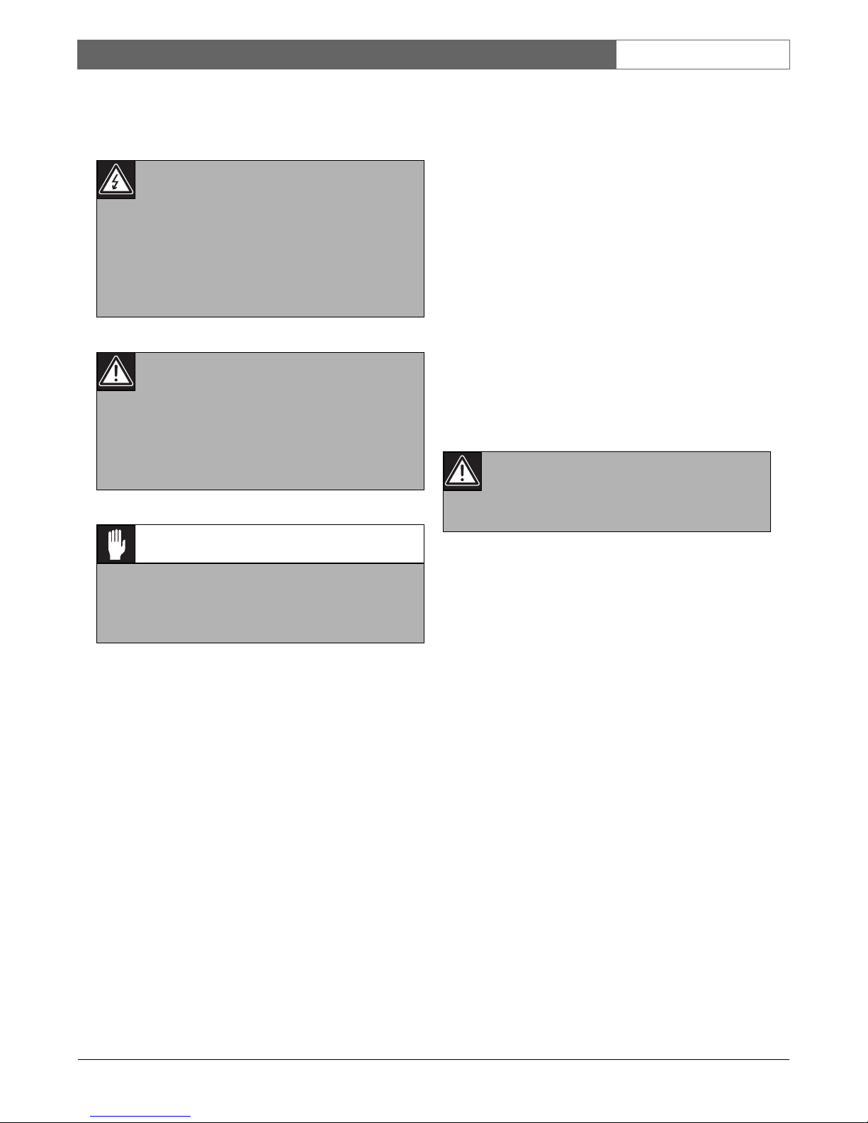
Danger
The lightning flash with arrowhead symbol,
within a triangle, is intended to alert the user to
the presence of uninstalled “dangerous voltage”
within the product's enclosure; that may be of
sufficient magnitude to constitute a risk of electric shock to persons.
Warning
The exclamation mark within a triangle is
intended to alert the user to the presence of
important operating and maintenance (servicing) instructions in the literature accompanying
the appliance.
Caution
To reduce the risk of electricschock, do not
remove cover (or back). No user - serviceable
parts inside. Refer servicing to qualified service
personnel
Warning
To reduce the risk of fire or electric shock, do
not expose this equipment to rain or moisture.

Bosch Security Systems | 2003-06
VSS7390/01T Switcher | Installation Manual | Chapter 1 EN | 3
Remark
Bosch has a strong commitment towards the environment. This monitor has been designed to respect the
environment as much as possible.
1.1.1 FCC Inform at i on
This equipment has been tested and found to comply
with the limits for a Class B digital device, pursuant to
part 15 of the FCC Rules. These limits are designed to
provide reasonable protection against harmful interference in a residential installation. This equipment generates, uses and can radiate radio frequency energy and, if
not installed and used in accordance with the instructions, may cause harmful interference to radio communications. However, there is no guarantee that
interference will not occur in a particular installation. If
this equipment does cause harmful interference to radio
or television reception, which can be determined by
turning the equipment off and on, the user is encouraged to try to correct the interference by one or more of
the following measures:
• Reorient or relocate the receiving antenna.
• Increase the separation between the equipment and
receiver.
• Connect the equipment into an outlet on a circuit
different from that to which the receiver is connected.
• Consult the dealer or an experienced radio/ TV
technician for help.
Note
Any change or modification not expressly approved by
Bosch of the equipment authorization could void the
user's authority to operate the equipment.
For additional information or to speak to a representative, please contact the Bosch Security Systems location
nearest you or visit our web site at www.boschsecuritysystems.com (See: Your Guide To Observation)
Caution
Danger of explosion if batteries are incorrectly
replaced. Replace only with the same or equivalent type.
Warning
This device is intended for use in public areas
only. Surreptitious recording of oral communica-
tions is strictly prohibited by U.S. Federal law
Bosch Security Systems | 2003-06
VSS7390/01T Switcher | Installation Manual | Chapter 2 EN | 4
2 Hardware Installation
This chapter describes the installation of the system
hardware. For details of operation, see the supplied
Operation Instructions.
Note
Ensure that you read all safety precautions.
2.1 SYSTEM CABLE
For the interconnection between the monitor and
camera a 15m/45ft system cable is supplied with the
camera. For an optimum picture and sound quality you
should always use 4-wire dual twisted-pair cable when
extending the connection. The maximum allowed cable
length is 200m/600ft. Pay attention that the connectors
are fixed to the cable corresponding to the figure below.
(Figure 3.1) If the length of the system cable is over
200m/600ft (up to 300m/900ft), an interface box should
be used to feed the accessory or camera (see optional
accessories in the Operation Instructions).
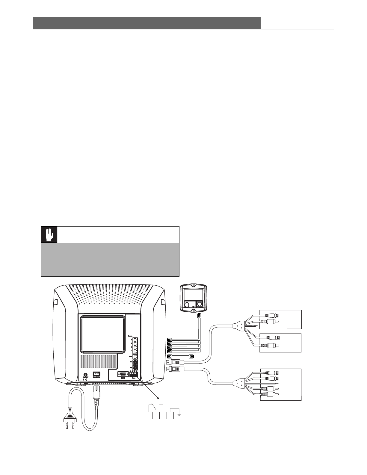
2.2 SYSTEM CONNECTION
2.2.1 Camera inputs (1 to 4)
The cameras are connected to inputs 1 through to 4,
depending on the number of cameras used.
2.2.2 Slave output
An output for a slave monitor (optional accessory) is
available.
2.2.3 Aux. output/input
You can configure an auxiliary output configuration via
the menu option (see System settings). The auxiliary
output provides loop-through from one of the 4 camera
inputs or presentation mode where you can connect
another video source to aux-in. It is possible to switch
between this video source and one of the camera
pictures.
Note
The supplied A/V cable can be used for Aux. output/
input connection. However, if you are using two Video
Recorders you will need to order a second A/V cable
(see your local supplier).
• Connect the Mini Din plug to the Aux. connector of
the system monitor.
• Connect the BNC connectors to the video in and
video output of the Video Recorder or CVBS monitor.
Caution
The plugs used for the observation system have
the same dimensions as standard telephone
plugs. (RJ-11) Never connect telephone equipment or cable to the observation system.
VIDEO
OUT
AUDIO
OUT
AUDIO
IN
VIDEO
IN
VIDEO
OUT
AUDIO
OUT
AUDIO
IN
VIDEO
IN
Time Lapse VCR
VIDEO OUT
VIDEO IN
NOT USED
AUDIO OUT
AUDIO IN
TO SLAVE
VIDEO OUT
AUDIO OUT
TV / MONITOR
VCR (PLAYBACK ONLY)
VIDEO IN
AUDIO IN
CAMERA 1..4
Not used
1234
ALARM
Figure 3.1: System Connection
 Loading...