

Bosch VMS, Video Management System Operator's Manual

Bosch Video Management System
en Operator's Manual


Table of contents
1
Using the Help 7
1.1 Finding information 7
1.2 Printing the Help 8
2
Introduction 9
3
System overview 11
3.1 Hardware requirements 11
3.2 Software requirements 12
3.3 License requirements 12
3.4 Supported system structures 12
4
Concepts 14
4.1 Enterprise System 14
4.1.1 Scenarios 14
4.1.2 Permissions 17
4.1.3 Types of user groups 18
4.1.4 Licensing 18
4.2 Server Lookup 18
4.3 Alarm handling 19
5
Getting started 22
5.1 Accessing the system 22
5.2 Using Server Lookup 22
5.3 Starting Operator Client 22
5.4 Working offline 23
5.5 Accepting a new configuration 24
6
Displaying camera images 25
6.1 Selecting a time zone 25
6.2 Displaying a camera in an Image pane 26
6.3 Displaying cameras from multiple Management Servers 26
6.4 Finding an item in the Logical Tree 26
6.5 Arranging Image panes 27
6.6 Displaying the Alarm Image window 27
6.7 Starting manual recording 27
6.8 Starting a pre-configured camera sequence 28
6.9 Starting an automatic camera sequence 28
6.10 Using one channel audio mode 29
6.11 Using multichannel audio mode 29
6.12 Using digital zoom 30
6.13 Saving a single image 30
6.14 Printing a single image 30
6.15 Switching to full-screen mode 31
6.16 Displaying or hiding the Image pane bars 31
6.17 Displaying information on a camera 31
6.18 Starting instant playback 31
6.19 Assigning a camera to a monitor 32
6.20 Using audio mode 32
6.21 Displaying metadata (for NVR recordings only) 32
6.22 Using the Intercom functionality 32
6.23 Locking the control of a PTZ camera 34
Bosch Video Management System Table of Contents | en 3
Bosch Sicherheitssysteme GmbH Operator's Manual 2013.07 | V1 | Operator Client

6.24 Updating the reference image 34
6.25 Controlling a monitor wall 34
6.26 Displaying video via low bandwidth 35
6.27 Using TCP for reliable connection 35
7
Using maps and the PTZ cameras 36
7.1 Displaying a map 36
7.2 Controlling PTZ cameras 36
7.3 Using in-window control of a camera 36
8
Using favorites and bookmarks 38
8.1 Adding items to the Favorites Tree 38
8.2 Creating/editing views 38
8.3 Adding a bookmark 39
8.4 Editing a bookmark 40
8.5 Loading a bookmark 40
8.6 Exporting bookmarks 40
9
Managing recorded videos 42
9.1 Selecting a time zone 42
9.2 Using the Timeline 43
9.3 Playing a specific recording mode 43
9.4 Playing recorded videos 43
9.5 Authenticating video data (for NVR recordings only) 44
9.6 Changing the playback speed 44
9.7 Protecting video 44
9.8 Deleting video data 45
9.9 Exporting video data 45
9.10 Importing video data 46
9.11 Performing a Forensic Search (only VRM recordings) 47
9.12 Finding motion (only NVR recordings) 47
9.13 Finding Logbook entries 48
9.14 Finding recorded video data 49
9.15 Displaying video via low bandwidth 49
10
Handling alarms 50
10.1 Accepting an alarm 50
10.2 Adding comments to an alarm 50
10.3 Clearing an alarm 51
10.4 Customizing the Alarm List window 51
10.5 Displaying the Live Image window 52
10.6 Starting a workflow 52
10.7 Un-accepting an alarm 52
11
Using a CCTV keyboard 54
11.1 Using KBD Universal XF keyboard 54
11.1.1 KBD Universal XF keyboard user interface 54
11.2 Bosch IntuiKey keyboard user interface 56
11.2.1 Status display 57
11.3 Using a Bosch IntuiKey keyboard connected to a workstation 58
11.3.1 Starting the keyboard 58
11.3.2 Entering operation modes 58
11.3.3 Displaying cameras 59
11.3.4 Using the joystick 59
4 en | Table of Contents Bosch Video Management System
2013.07 | V1 | Operator Client Operator's Manual Bosch Sicherheitssysteme GmbH

11.3.5 Using softkeys 60
11.4 Using a Bosch IntuiKey keyboard connected to a decoder 62
11.4.1 Starting the keyboard 62
11.4.2 Displaying cameras 62
11.4.3 Using the joystick 62
11.4.4 Using softkeys 63
12
User interface 64
12.1 Live Mode 64
12.2 Playback Mode window 67
12.3 Alarm Mode (Alarm Display) 70
12.4 Menu commands 74
12.5 Triggering a user event 76
12.6 Reference Image dialog box 76
12.7 Please select a Server 76
12.8 Select Search Parameters dialog box 77
12.9 ATM/POS Options dialog box 78
12.10 Select Virtual Inputs Filter Settings dialog box 79
12.11 Device Selection dialog box 79
12.12 Event Selection dialog box 79
12.13 Logbook Results: dialog box 79
12.14 Options dialog box 79
12.15 Logical Tree window 80
12.16 Search dialog box 81
12.17 Favorites Tree window 81
12.18 Export Video dialog box 81
12.19 Bookmarks window 82
12.20 Add Bookmark dialog box 83
12.21 Export Bookmark dialog box 83
12.22 Export Multiple Bookmarks dialog box 84
12.23 Exports window 85
12.24 Map window 85
12.25 Monitor Wall Image window 85
12.26 PTZ Control window 86
12.27 Monitors window 87
12.28 Image window 87
12.29 Image pane 88
12.30 Timeline window 89
12.31 Motion Search dialog box 91
12.32 Delete Video dialog box 91
12.33 Forensic Search dialog box (only VRM recordings) 92
12.34 Protect Video dialog box 92
12.35 Unprotect Video dialog box 93
12.36 Motion Search Results window 93
12.37 Video Search Results window 93
12.38 Alarm List window 93
12.39 Used icons 94
13
Keyboard shortcuts 98
13.1 General controls 98
13.2 Playback controls 98
Bosch Video Management System Table of Contents | en 5
Bosch Sicherheitssysteme GmbH Operator's Manual 2013.07 | V1 | Operator Client

13.3 Image window controls 98
14
Troubleshooting 99
14.1 Updating an old Bosch VMS Archive Player version 99
Glossary 100
Index 104
6 en | Table of Contents Bosch Video Management System
2013.07 | V1 | Operator Client Operator's Manual Bosch Sicherheitssysteme GmbH

Using the Help
To find out more about how to do something in Bosch VMS, access the online Help using any
of the following methods.
To use the Contents, Index, or Search:
4 On the Help menu, click Help. Use the buttons and links to navigate.
To get Help on a window or dialog:
4 On the toolbar, click
.
OR
4 Press F1 for help on any program window or dialog.
Finding information
You can find information in the Help in several ways.
To find information in the Online Help:
1. On the Help menu, click Help.
2. If the left-hand pane is not visible, click the Show button.
3. In the Help window, do the following:
Click: To:
Contents Display the table of contents for the Online Help. Click each book to
display pages that link to topics, and click each page to display the
corresponding topic in the right-hand pane.
Index Search for specific words or phrases or select from a list of index
keywords. Double-click the keyword to display the corresponding topic
in the right-hand pane.
Search Locate words or phrases within the content of your topics. Type the
word or phrase in the text field, press ENTER, and select the topic you
want from the list of topics.
Texts of the user interface are marked bold.
4 The arrow invites you to click on the underlined text or to click an item in the application.
Related Topics
4 Click to display a topic with information on the application window you currently use.
This topic provides information on the application window controls.
Concepts provides background information on selected issues.
Caution!
Medium risk (without safety alert symbol): Indicates a potentially hazardous situation.
If not avoided, this may result in property damage or risk of damage to the unit.
Cautionary messages should be heeded to help you avoid data loss or damaging the system.
Notice!
This symbol indicates information or a company policy that relates directly or indirectly to the
safety of personnel or protection of property.
1
1.1
Bosch Video Management System Using the Help | en 7
Bosch Sicherheitssysteme GmbH Operator's Manual 2013.07 | V1 | Operator Client

Printing the Help
While using the Online Help, you can print topics and information right from the browser
window.
To print a Help topic:
1. Right-click in the right pane and select Print.
The Print dialog box opens.
2. Click Print. The topic is printed to the specified printer.
1.2
8 en | Using the Help Bosch Video Management System
2013.07 | V1 | Operator Client Operator's Manual Bosch Sicherheitssysteme GmbH
Introduction
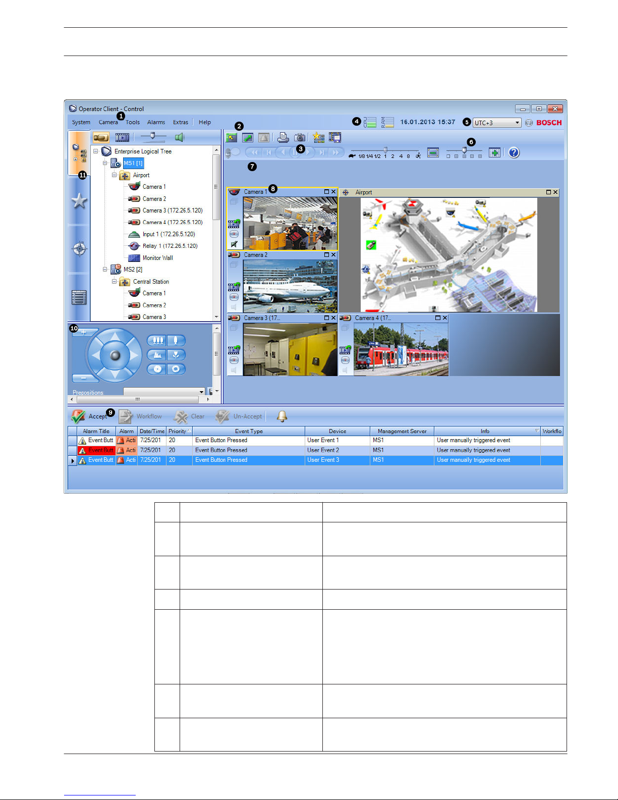
1 Menu bar Allows you to select a menu command.
2 Toolbar Displays the available buttons. Point to an icon to
display a tooltip.
3 Playback controls Allows you to control instant playback or a camera
sequence or alarm sequence.
4 Performance meter Displays the CPU usage and the memory usage.
5 Time zone selector Select an entry for the time zone to be displayed in
most time related fields.
Only available if at least one Management Server in
the Logical Tree is located in another time zone as
your Operator Client.
6 Slider for Image pane pattern Allows you to select the required number of Image
panes.
7 Image window Displays the Image panes. Allows you to arrange the
Image panes.
2
Bosch Video Management System Introduction | en 9
Bosch Sicherheitssysteme GmbH Operator's Manual 2013.07 | V1 | Operator Client
8 Image pane Displays a camera, a map, an image, a document
(HTML file).
9
Alarm List window
Displays all alarms that the system generates.
Allows you to accept or clear an alarm or to start a
workflow, for example, by sending an E-mail to a
maintenance person.
The Alarm List is not being displayed, when the
connection to the Management Server is lost.
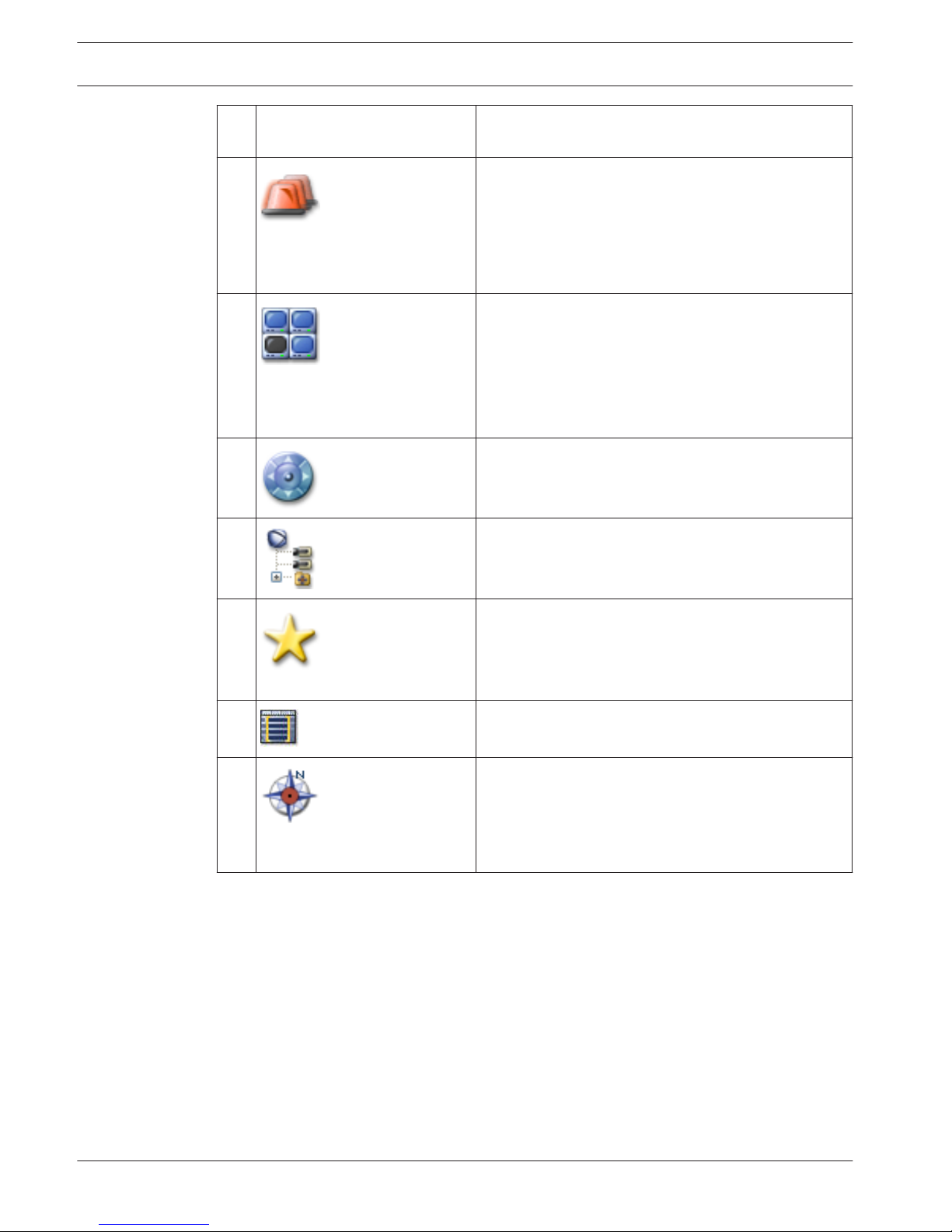
10
Monitors window
(only available if at least one
analog monitor group has been
configured)
Displays the configured analog monitor groups.
Allows you to switch to the next or previous analog
monitor group if available.
Note:
The Monitors tab is not visible if your Operator Client
is connected to more than one Management Server.
PTZ Control window
Allows you to control a PTZ camera.
11
Logical Tree window
Displays the devices your user group has access to.
Allows you to select a device for assigning it to an
Image pane.
Favorites Tree
window
Allows you to organize the devices of the Logical Tree
as required.
Bookmarks window
Allows to manage bookmarks.
Map window
Displays a site map. Allows you to drag the map to
display a particular section of the map.
If activated, a map is displayed automatically for each
camera displayed in an Image pane. In this case, the
camera must be configured on a map.
This manual guides you through the basic steps of the configuration and operation with
Bosch VMS.
For detailed help and step-by-step instructions read the Configuration Manual and the
Operator’s Manual or use the Online Help. You find the manuals as PDF files on your
Setup CD.
Bosch VMS Archive Player displays exported recordings.
10
en | Introduction Bosch Video Management System
2013.07 | V1 | Operator Client Operator's Manual Bosch Sicherheitssysteme GmbH

System overview
If you plan to install and configure Bosch VMS, participate in a system training on Bosch VMS.
Refer to the Release Notes of the current Bosch VMS version for supported versions of
firmware and hardware and other important information.
See data sheets on Bosch workstations and servers for information on computers where
Bosch VMS can be installed.
The Bosch VMS software modules can optionally be installed on one PC.
Important components
– Management Server (selectable in Setup): Stream management, alarm management,
priority management, Management logbook, user management, device state management.
Additional Enterprise System license: Managing Enterprise User Groups and Enterprise
Accounts.
– Configuration Wizard: Easy and fast setup of a recording system.
– Configuration Client (selectable in Setup): System configuration and administration for
Operator Client.
– Operator Client (selectable in Setup): Live monitoring, storage retrieval and playback,
alarm and accessing multiple Management Server computers simultaneously.
– Video Recording Manager (selectable in Setup): Distributing storage capacities on iSCSI
devices to the encoders, while handling load balancing between multiple iSCSI devices.
Streaming playback video and audio data from iSCSI to Operator Clients.
– Mobile Video Service (selectable in Setup): Provides a transcoding service that
transcodes the live and recorded video stream from a camera configured in Bosch VMS to
the available network bandwidth. This service enables video clients like an iPhone or a
Web client to receive transcoded streams, for example for unreliable network
connections with limited bandwidth. Not supported on Windows XP.
– Web Client: You can access live and playback videos via Web browser.
– Mobile App: You can use the Mobile App on iPhone or iPad to access live and playback
video.
– Bosch Video Streaming Gateway (selectable in Setup): Provides the integration of 3rd
party cameras and NVR-like recording, e.g. in low-bandwidth networks.
– Cameo SDK (selectable in Setup): The Cameo SDK is used to embed Bosch VMS live and
playback Image panes to your external third-party application. The Image panes follow the
Bosch VMS based user permissions.
The Cameo SDK provides a subset of the Bosch VMS Operator Client functionalities that
enables you to create applications similar to the Operator Client.
– Client Enterprise SDK: The Client Enterprise SDK is meant to control and monitor the
behaviour of Operator Client of an Enterprise System by external applications. The SDK
allows to browse devices that are accessible by the running, connected Operator Client
and to control some UI functionalities.
– Client SDK / Server SDK: The Server SDK is used to control and monitor the Management
Server by scripts and external applications. You can use those interfaces with a valid
administrator account.
The Client SDK is used to control and monitor the Operator Client by external
applications and scripts (part of the related server configuration).
Hardware requirements
See the data sheet for Bosch VMS. Data sheets for platform PCs are also available.
3
3.1
Bosch Video Management System System overview | en 11
Bosch Sicherheitssysteme GmbH Operator's Manual 2013.07 | V1 | Operator Client
Software requirements
See the data sheet for Bosch VMS.
Bosch VMS must not be installed on a computer where you want to install Bosch VMS Archive
Player.
License requirements
See the data sheet for Bosch VMS for the available licenses.
Supported system structures
An operator or installer can be responsible for the following system structures:
– Single server system
– Multi server system (Enterprise System)
– Multi system environment
System with access point for logon
Single server system,
System access point: Management Server
Enterprise System,
System access point: Enterprise Management Server
3.2
3.3
3.4
12 en | System overview Bosch Video Management System
2013.07 | V1 | Operator Client Operator's Manual Bosch Sicherheitssysteme GmbH
1 Multi system environment 4 System access point:
Server on which logon request of an
operator or installer is processed.
2 Single server system 5 Management Server
3 Multi server system 6 Enterprise Management Server
Use cases for multi system access
Two Bosch VMS features valid for multi system environments are available:
– Enterprise System
– Server Lookup
An operator might want to access a multi system environment for the following reasons:
– Configure multiple systems (Server Lookup)
– Maintenance and monitoring of multiple systems (Server Lookup)
– Alert (SMS, Email 3rd party) driven on-demand monitoring of multiple systems (Server
Lookup)
– Simultaneous connection to multiple servers for seamless operation of one distributed
system (Enterprise System)
Related Topics
– Enterprise System, page 14
– Server Lookup, page 18
Bosch Video Management System
System overview | en 13
Bosch Sicherheitssysteme GmbH Operator's Manual 2013.07 | V1 | Operator Client

Concepts
This chapter provides background information on selected issues.
Enterprise System
The target of a Bosch VMS Enterprise System is to enable a user of Operator Client to
simultaneously access multiple Management Servers.
Related Topics
– Accessing the system, page 22
Scenarios
The following three scenarios are covered.
– Scenario 1: A dedicated server plays the role of Enterprise Management Server. This
server has the only task to manage the simultaneous access of an Operator Client
workstation to multiple Management Servers.
An Operator Client workstation logs on to Enterprise Management Server. After successful
logon the user of Operator Client has access to the devices of all configured
Management Servers according to the permissions in his Enterprise User Group.
4
4.1
4.1.1
14 en | Concepts Bosch Video Management System
2013.07 | V1 | Operator Client Operator's Manual Bosch Sicherheitssysteme GmbH
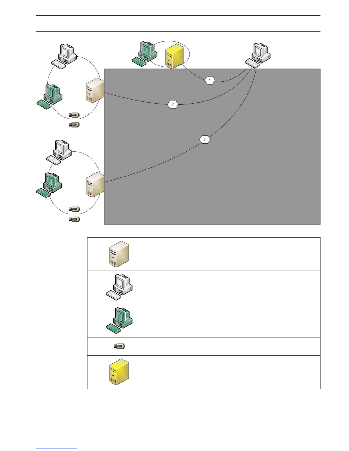
Figure 4.1: Enterprise Scenario 1
Management Server
Operator Client
Configuration Client
IP camera / encoder
Enterprise Management Server
Bosch Video Management System Concepts | en 15
Bosch Sicherheitssysteme GmbH Operator's Manual 2013.07 | V1 | Operator Client
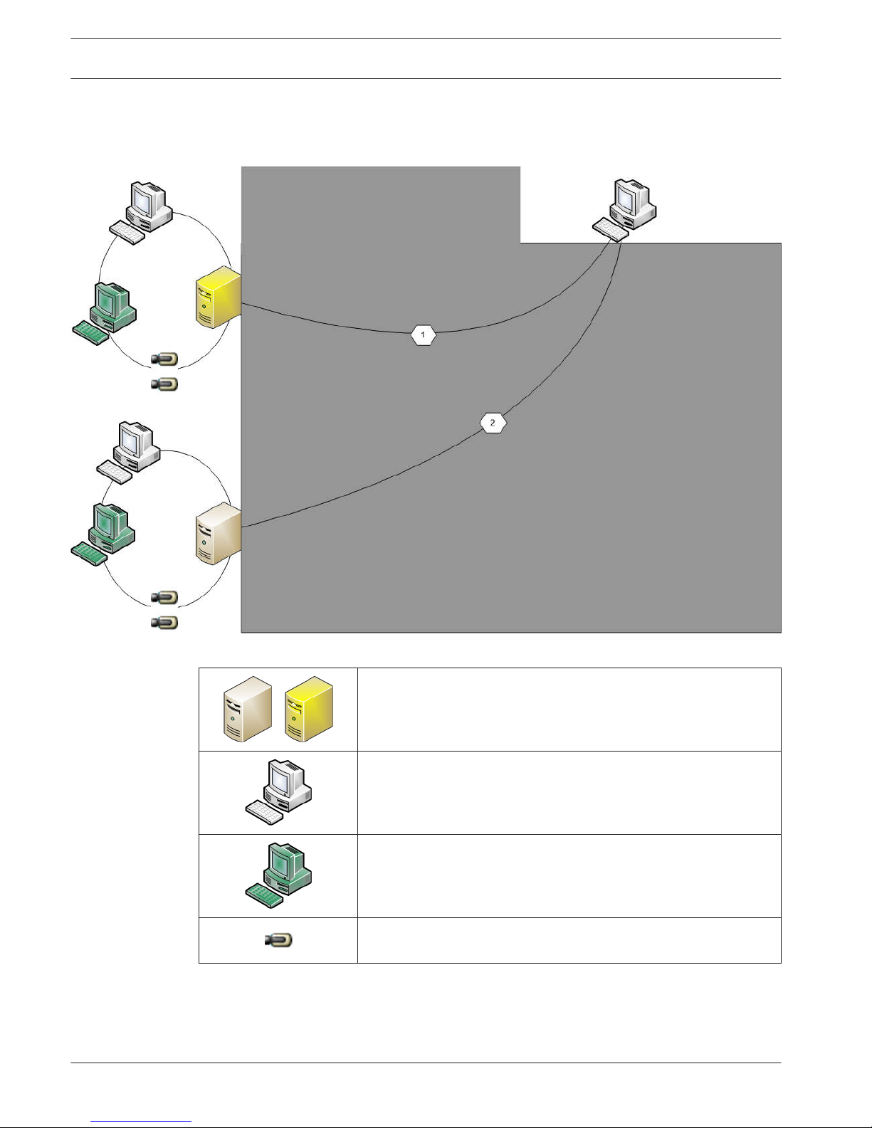
– Scenario 2: Combination of Enterprise Management Server and Management Server role.
In this case the own Management Server must also be part of the Enterprise Management
Server configuration.
Figure 4.2: Enterprise Scenario 2
/
Management Server / Enterprise Management Server
Operator Client
Configuration Client
IP camera / encoder
– Scenario 3: The classic client-server architecture remains supported.
16 en | Concepts Bosch Video Management System
2013.07 | V1 | Operator Client Operator's Manual Bosch Sicherheitssysteme GmbH
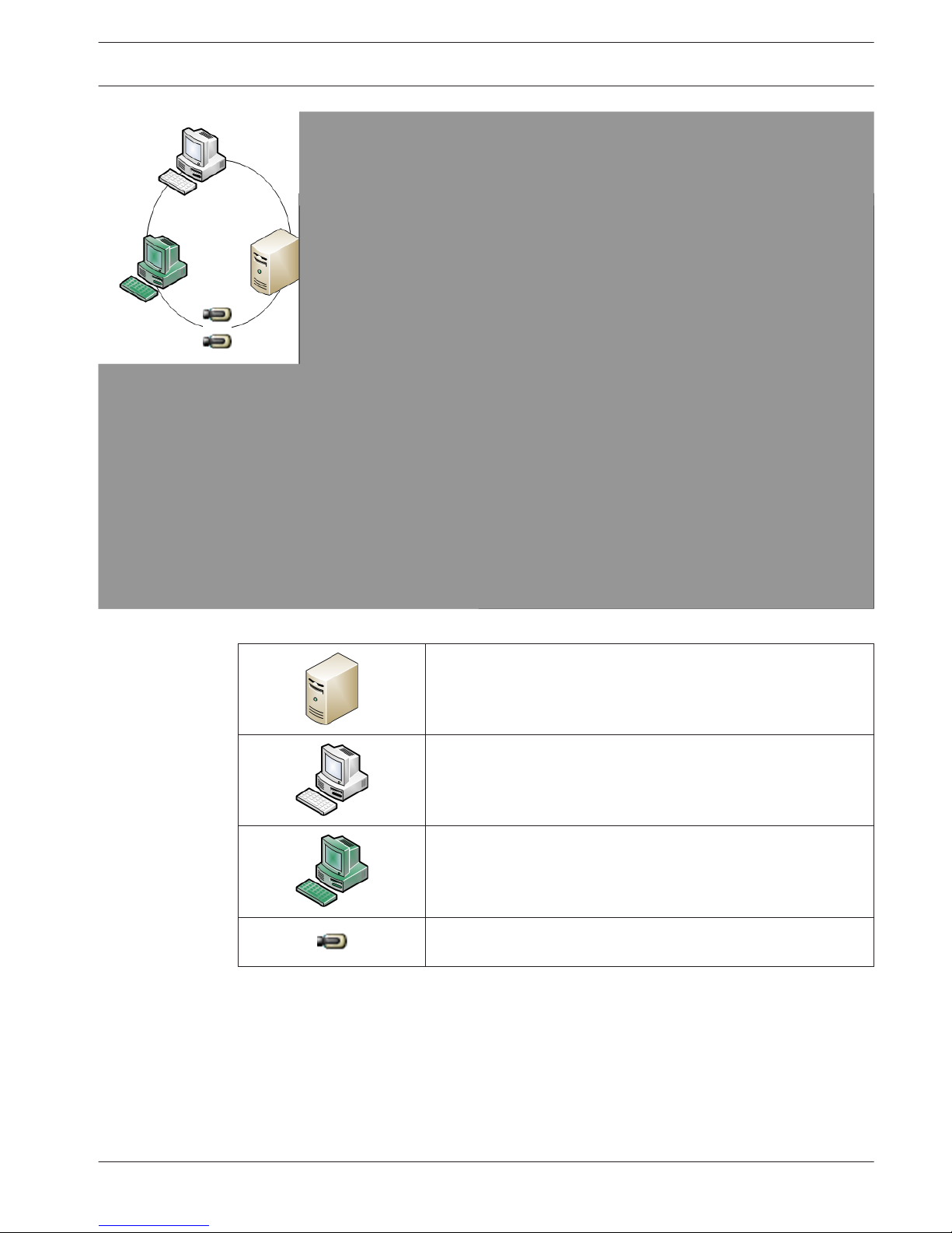
Figure 4.3: Classic Scenario 3
Management Server
Operator Client
Configuration Client
IP camera / encoder
Permissions
Permissions on an Enterprise System
For an Enterprise System you configure the following permissions:
– Operating permissions of Operator Client defining the user interface for operating in the
Enterprise System, for example the user interface of the alarm monitor.
Use an Enterprise User Group. Configure it on the Enterprise Management Server.
4.1.2
Bosch Video Management System Concepts | en 17
Bosch Sicherheitssysteme GmbH Operator's Manual 2013.07 | V1 | Operator Client

– Device permissions that should be available for operating in an Enterprise Management
Server are defined on each Management Server.
Use Enterprise Accounts. Configure it on each Management Server.
Permissions on a single Management Server
For managing the access to one of the Management Servers, use the standard user group. You
configure all permissions on this Management Server in this user group.
You can configure dual authorization user groups for standard user groups and for Enterprise
User Groups.
Types of user groups
Type Contains Available configuration
settings
Where do you
configure?
User group Users – Operating and device
permissions
– Management
Server
Enterprise User
Group
Users – Operating permissions
– Per Management
Server: Name of the
corresponding
Enterprise Access
Accounts with logon
credentials
– Enterprise
Management
Server
Enterprise Access – – Device permissions
– Account password
– Management
Server
Dual authorization
user group
User groups – See user groups – See user groups
Enterprise dual
authorization
Enterprise User
Groups
– See Enterprise User
Groups
– See Enterprise
User Groups
Table 4.1: User groups
Licensing
Bosch VMS Enterprise (MBV-BENT) version license is required at each Enterprise Management
Server to enable the feature.
For each Management Server assigned to one or more Enterprise User Groups, 1 license
(MBV-XSUB) is required.
To update an existing MBV-BPRO Base license to an Enterprise System, you need an
Enterprise Upgrade license (MBV-FEUP).
Each Workstation connecting to an Enterprise Management Server requests one MBV-XWST
that is licensed at Enterprise Management Server. No additional MBV-XWST license is required
on each Management Server if accessed via Enterprise Management Server.
Server Lookup
A single user of Configuration Client or Operator Client may want to connect to multiple
system access points sequentially. This access is called Server Lookup. System access points
can be Management Server or Enterprise Management Server.
Server Lookup supports you in locating system access points by their names or descriptions.
The user retrieves the list of system access points during logon. He needs to connect to the
server hosting the configuration with Server List (Server List Provider).
4.1.3
4.1.4
4.2
18 en | Concepts Bosch Video Management System
2013.07 | V1 | Operator Client Operator's Manual Bosch Sicherheitssysteme GmbH
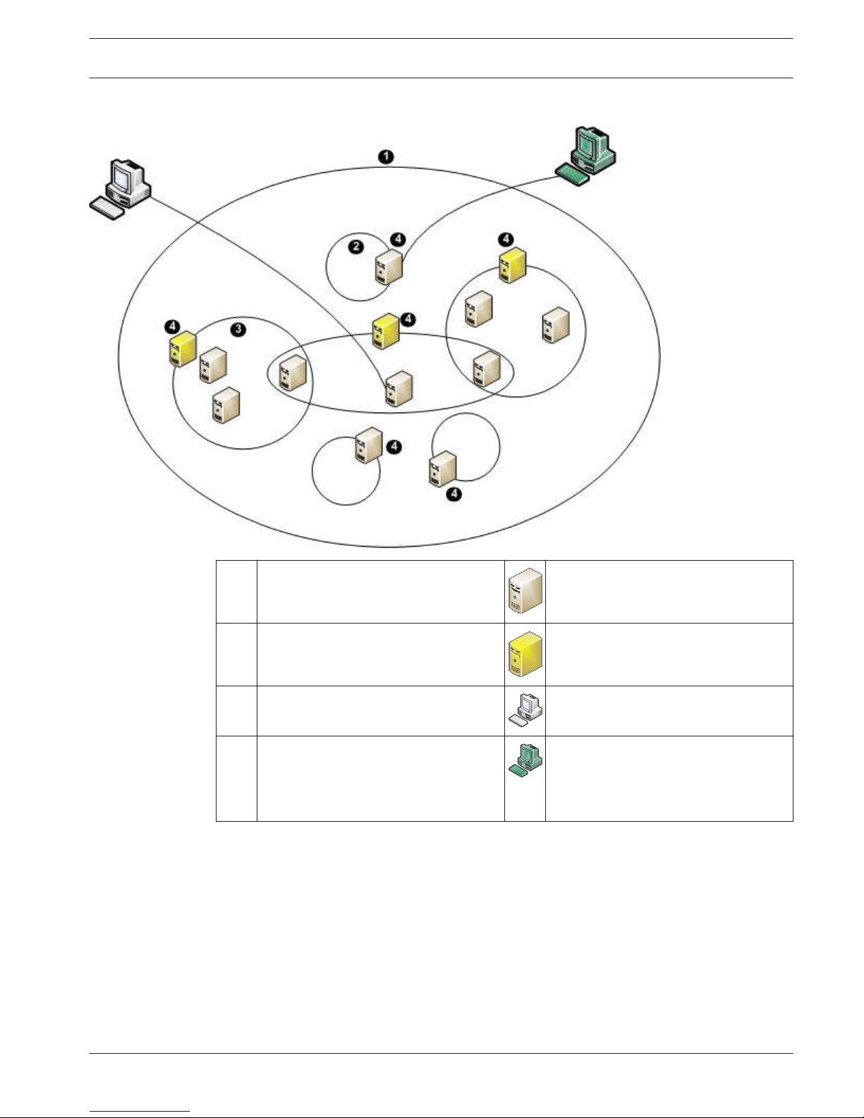
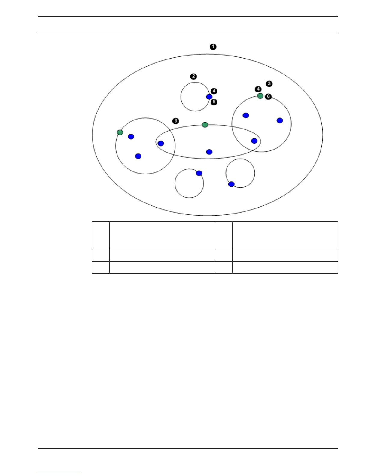
The following image shows an example for Server Lookup in a multi system environment:
1 Multi system environment Management Server
2 Single server system Enterprise Management Server
3 Multi server system Operator Client
4 System access point:
Server on which logon request of
Operator Client or Configuration Client
is processed.
Configuration Client
When a client logs on to Enterprise Management Server, it is possible to get access to all
Management Servers of this Enterprise System simultaneously.
Related Topics
– Using Server Lookup, page 22
Alarm handling
Alarms can be individually configured to be handled by one or more user groups. When an
alarm occurs, it appears in the Alarm List of all users in the user groups configured to receive
that alarm. When any one of these users starts to work on the alarm, it disappears from the
Alarm List of all other users.
Alarms are displayed on a workstation’s alarm monitor and optionally on analog monitors. This
behavior is described in the following paragraphs.
4.3
Bosch Video Management System Concepts | en 19
Bosch Sicherheitssysteme GmbH Operator's Manual 2013.07 | V1 | Operator Client

Alarm flow
1. An alarm occurs in the system.
2. Alarm notifications appear in the Alarm Lists of all users configured for this alarm. Alarm
video is immediately displayed on configured monitors. If it is an automatically displayed
alarm (auto pop-up), the alarm video is also automatically displayed on the
Operator Client workstation’s alarm monitors.
If the alarm is configured as an auto-clear alarm, the alarm is removed from the Alarm List
after the auto-clear time (configured in the Configuration Client).
On analog monitors, any quad views from VIP XDs are temporarily replaced by full-screen
displays.
3. One of the users accepts the alarm. The alarm video is then displayed on this user's
workstation (if it is not already displayed via auto pop-up). The alarm is removed from all
other Alarm Lists and alarm video displays.
4. The user who accepted the alarm invokes a workflow that can include reading an action
plan and entering comments. This step is optional - requirements for workflow can be
configured by the administrator.
5. Finally, the user clears the alarm. This removes the alarm from his Alarm List and alarm
display.
On an analog monitor group, the monitors return to the cameras that were displayed
before the alarm occurred.
Alarm Image window
1. To display alarm video, the Alarm Image window replaces the Live or Playback Image
window on the monitor that has been configured for alarm display.
2. Each alarm gets a row of Image panes. Up to 5 Image panes can be associated with each
alarm. These Image panes can display live video, playback video, or maps.
On an analog monitor group, each alarm can call up cameras on a row of analog monitors.
The number of cameras in the row is limited by the number of columns in the analog
monitor group. Monitors in the row that are not used for alarm video can be configured to
either continue with their current display or to display a blank screen.
3. Higher priority alarms are displayed above lower priority alarms on both analog monitor
rows and the Operator Client workstation display alarm rows.
4. If the Alarm Image window is completely full of Alarm Image rows and an additional alarm
must be displayed, the lowest priority alarms "stack up" in the bottom row of the Alarm
Image window. You can step through the stacked alarms with the controls at the left side
of the alarm row.
You can step through the alarm stacks on analog monitor groups with control buttons in
the Monitors window of the Operator Client workstation display. Analog monitors in
alarm are indicated by red icons with blinking "LEDs".
The alarm title, time, and date can be optionally be displayed on all analog monitors, or
only the first monitor in the alarm row.
5. For equal priority alarms, the administrator can configure the order behavior:
– Last-in-First-out (LIFO) mode: in this configuration, new alarms are inserted above
older alarms of the same priority.
– First-in-First-out (FIFO) mode; in this configuration, new alarms are inserted below
older alarms of the same priority.
6. An alarm's Image row can appear in the Alarm Image window in one of two ways:
– When it is generated (auto pop-up). This occurs when the alarm priority is higher
than display priority.
– When the alarm is accepted. This occurs when the alarm priority is lower than
display priority.
20
en | Concepts Bosch Video Management System
2013.07 | V1 | Operator Client Operator's Manual Bosch Sicherheitssysteme GmbH

Auto pop-up alarms
Alarms can be configured to automatically display (pop up) in the Alarm Image window, based
on the alarm priority. Each user group's live and playback displays are also assigned priorities.
When alarms are received with priority higher than that of the user's display, the alarm
automatically displays its alarm row in the Alarm Image window. If the Alarm Image window is
not currently displayed, it automatically replaces the Live or Playback Image window on the
alarm-enabled monitor.
Although auto pop-up alarms are displayed in the Alarm Image window, they are not
automatically accepted. They can be displayed on multiple users' displays simultaneously.
When a user accepts an auto pop-up alarm, it is removed from all other users Alarm Lists and
alarm displays.
Related Topics
– Handling alarms, page 50
Bosch Video Management System Concepts | en 21
Bosch Sicherheitssysteme GmbH Operator's Manual 2013.07 | V1 | Operator Client

Getting started
This chapter provides information on how to get started with Bosch VMS and with Bosch VMS
Archive Player
Accessing the system
You access a system performing the following steps:
1. Perform one of the following steps to select the network address of the desired system:
– Click a preselected list entry.
– Enter a network address manually .
– Select a network address using Server Lookup.
2. Log on to the desired system:
– Single server system
– Enterprise System
Using Server Lookup
A single user of Configuration Client or Operator Client may want to connect to multiple
system access points sequentially. This access is called Server Lookup. System access points
can be Management Server or Enterprise Management Server.
Server Lookup supports you in locating system access points by their names or descriptions.
The user retrieves the list of system access points during logon. He needs to connect to the
server hosting the configuration with Server List (Server List Provider).
To access:
1. Start Operator Client or Configuration Client.
The logon dialog box is displayed.
2. In the Connection: list, select <Browse...>.
If private and public IP address has been configured for a server, this is indicated.
If you select <Browse...> for the first time, the Server List Provider dialog box is
displayed.
3. In the (Enterprise) Management Server Address: field, type in a valid network address of
the desired server.
4. Enter a valid user name and password.
5. If required, click Remember Settings.
6. Click OK.
The Server Lookup dialog box is displayed.
7. Select the desired server.
8. Click OK.
9. If the selected server has both a private and a public network address, a message box is
displayed asking whether you are using a computer located in the private network of the
selected server.
The server name is added to the Connection: list in the logon dialog box.
10. Select this server in the Connection: list and click OK.
If you have selected the Remember Settings check box, you can select this server directly
when you again want to access this server.
Starting Operator Client
Note:
– Before using the system, activate the licenses that you have ordered. The Configuration
Manual or the Configuration Client Online Help describe how to activate the licenses.
5
5.1
5.2
5.3
22 en | Getting started Bosch Video Management System
2013.07 | V1 | Operator Client Operator's Manual Bosch Sicherheitssysteme GmbH

– To be sure that your Bosch VMS uses the language that you need, please configure this
language in your Configuration Client. See the Online Help for details.
If a newer version of the application is stored on the Management Server, this version is
installed automatically by no-touch deployment when you log on.
To start Operator Client:
1. From the Start menu, select Programs > Bosch VMS > Operator Client.
The dialog box for logging on is displayed.
2. In the User Name: field, type your user name.
When you start the application for the first time, type Admin as user name, no password
required.
To access multiple Management Server computers simultaneously, type the user name of
a member of an Enterprise Group.
3. In the Password: field, type your password.
4. In the Connection: list, select the IP address or the DNS name of the Management Server
or Enterprise Management Server.
5. Click OK.
If dual authorization has been configured for your user group, the next logon dialog is
displayed.
A user of the configured second user group enters the required information.
The application starts.
If dual authorization is optional, just click OK again on the second logon dialog box. But
you then only have the user rights of your user group and not the potentially extended
user rights of your dual authorization group.
To quit Operator Client:
1. On the System menu, click Exit.
The application quits.
If you logged on to Operator Client as a user who is not authorized to quit the
application, the Enter Logoff Password dialog box is displayed.
2. Ask a user with corresponding user rights to enter his user name and password to
confirm the process.
Working offline
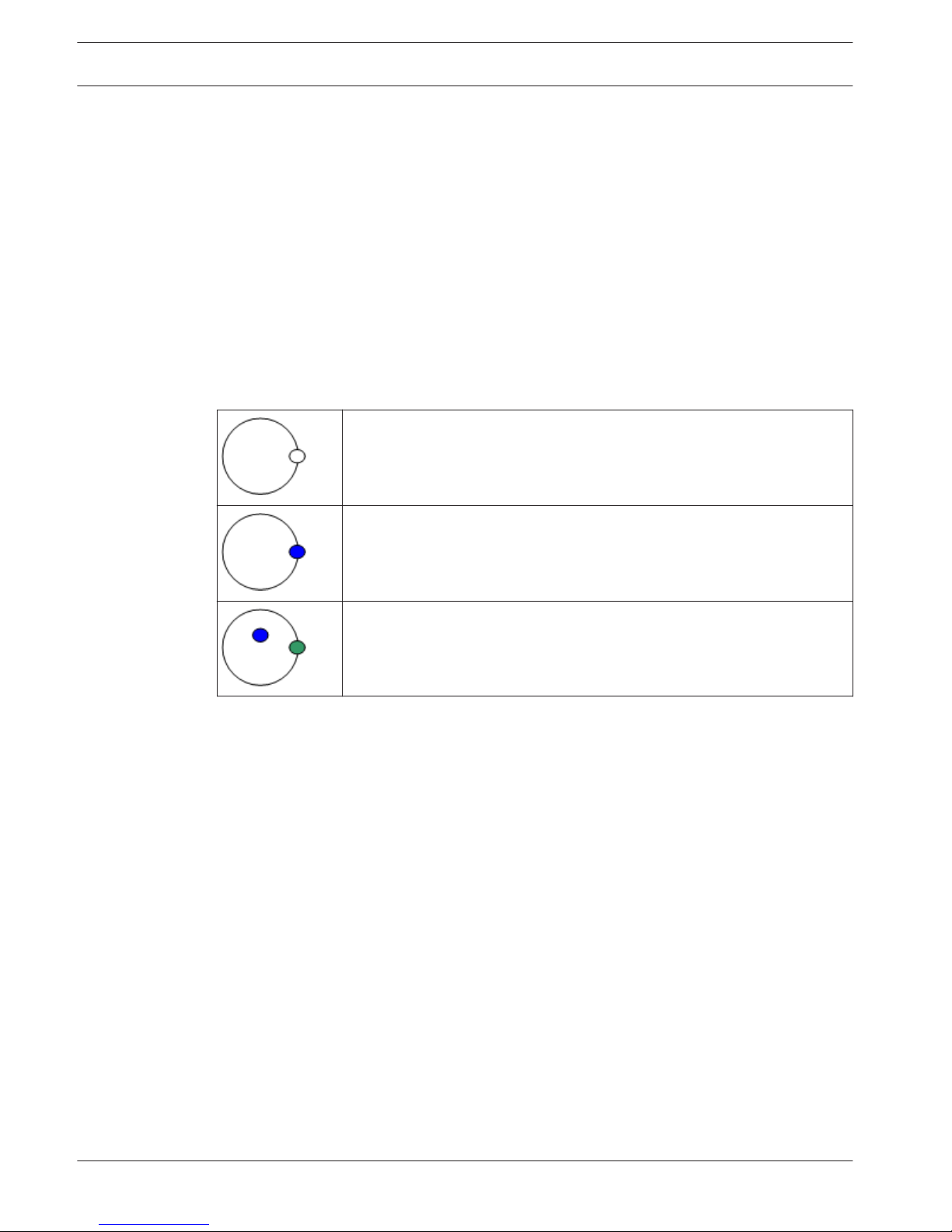
When Operator Client is disconnected from a Management Server, a respective overlay icon is
displayed in the Logical Tree on the disconnected Management Server. You can continue
working with Operator Client even if the disconnection lasts longer, but some functions are
not available.
If the connection to the Management Server is reestablished, a respective overlay icon is
displayed.
If a new configuration on a Management Server has been activated, a respective icon is
displayed in the Logical Tree on the icon of the affected Management Server and a dialog box
is displayed for some seconds. Accept or refuse the new configuration.
If your Operator Client instance is scheduled to log off at a specific point in time, this logoff
occurs even when the connection to the Management Server is not reestablished at this point
in time.
When disconnected from a Management Server, all devices are indicated with the icon. The
state overlay of a device in the Logical Tree or on a map when Operator Client is disconnected
from the Management Server
The following functions are not available in Operator Client when disconnected from the
Management Server for this connection:
5.4
Bosch Video Management System Getting started | en 23
Bosch Sicherheitssysteme GmbH Operator's Manual 2013.07 | V1 | Operator Client

– Handling alarms, Alarm List
– Indication of recording
– Indication of state changes
– PTZ control locking
– Analog monitor group
– Scripts
Accepting a new configuration
When the system administrator activates a new configuration from within Configuration Client,
each Operator Client is either immediately restarted automatically or the user of a workstation
is informed about the new configuration and can accept it later. The system administrator
configures which of these 2 cases occurs.
If the system administrator activated a new configuration without forcing each Operator Client
workstation to accept the new configuration, a dialog box is displayed on all Operator Client
workstations. The users can refuse or accept the new configuration. The dialog box is closed
after a few seconds without user interaction. In this case the new configuration is refused. If a
device (for example a camera) is removed from the system in the new configuration, some
functions of this device are not available if you have refused the new configuration.
If you change the password for a user or delete a user while this user is logged on, this user
can still continue working with Operator Client after password change or deletion. If after
password change or deletion the connection to Management Server is interrupted (for
example after activating the configuration), the user cannot automatically reconnect to the
Management Server again without logoff/logon at Operator Client.
To accept a new configuration:
4 Log off and then log on again.
The new configuration is used now.
5.5
24 en | Getting started Bosch Video Management System
2013.07 | V1 | Operator Client Operator's Manual Bosch Sicherheitssysteme GmbH
Displaying camera images
This chapter provides information on how to display camera images.
Some of the features described in this chapter can be deactivated for your user group.
Selecting a time zone
Main window
Notice!
Ensure that the time on all computers of your system is set correctly according to each time
zone where the computers are located.
Management Server and all connected devices including encoders, decoders, VRM Server
computers, DiBos and DVR devices must be in the same time zone. Operator Client computers
(including Client SDK and Cameo SDK) and Configuration Client computers can be in other
time zones than the Management Server.
If your Operator Client is located in another time zone than one or more connected
Management Server computers, you can select for display in the user interface:
– Your local time
– UTC
– Time zone of the Management Server computer you are connected to
The Image panes displaying a camera (live and playback) always show the time of the
corresponding Management Server.
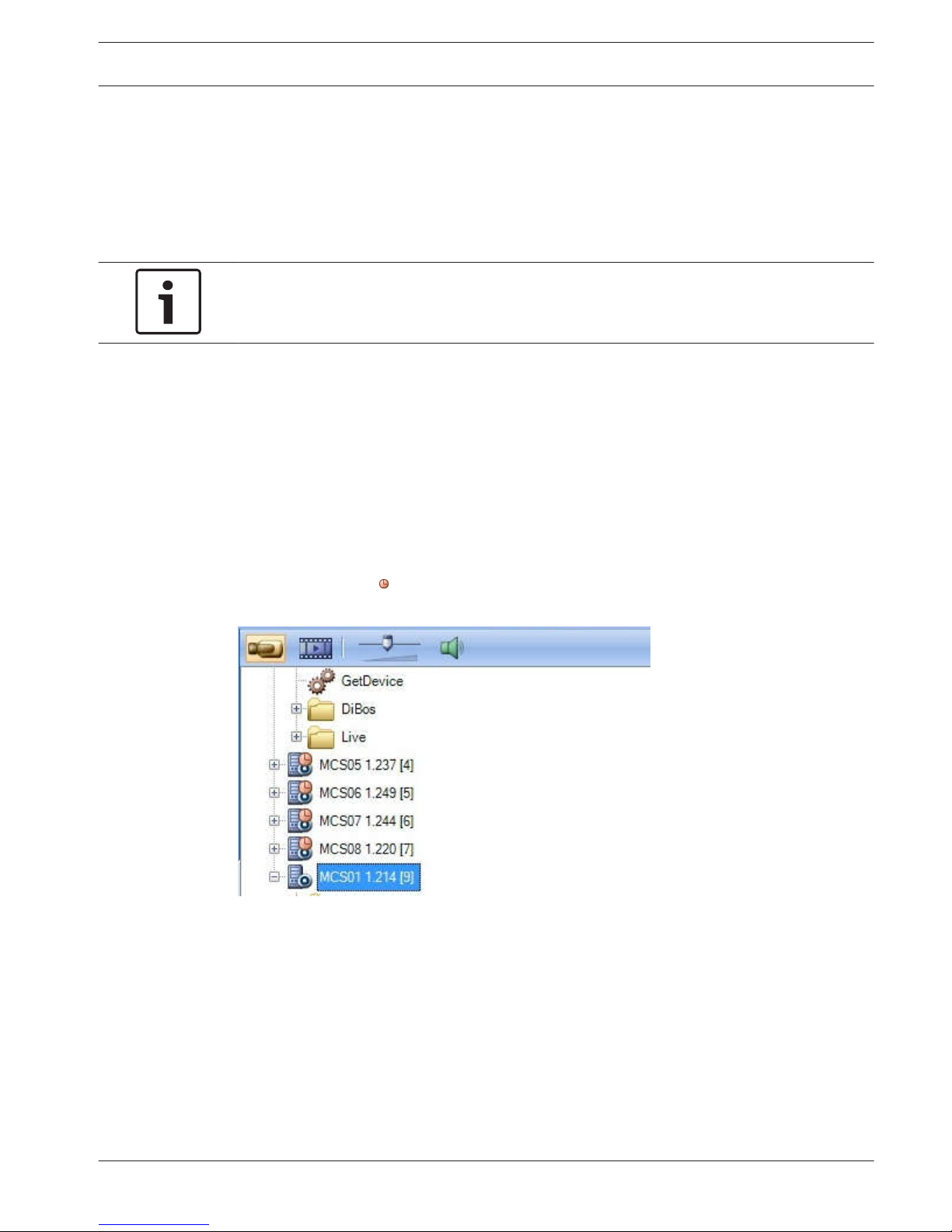
In the Logical Tree,
is displayed on the device icon for all servers that do not share the time
zone that is currently selected in the Operator Client:
You can select the time zone of a server for displaying this time zone in Operator Client.
To select the time zone:
1. In the Logical Tree, right-click a server icon to select the time zone of this server.
2. In the time zone selector list, select the desired entry.
– Local Time: Operator Client
– UTC
6
6.1
Bosch Video Management System Displaying camera images | en 25
Bosch Sicherheitssysteme GmbH Operator's Manual 2013.07 | V1 | Operator Client

– UTC–x: time zone of each available Management Server
The time based on the selected time zone is displayed in the menu bar:
Displaying a camera in an Image pane
Main window
To assign a camera image to an Image pane:
4 Drag a camera from the Logical Tree window to an Image pane.
The selected camera image is displayed in the Image pane.
Or:
1. Select an Image pane.
2. In the Logical Tree window, double-click a camera.
The selected camera image is displayed in the Image pane.
3. Repeat the above steps for every camera you want to display.
You can also drag maps and documents to Image panes.
Or:
4 In the Logical Tree, right-click a camera and click Show in next free Image pane.
The camera is displayed.
To move a camera within the Image window:
4 Drag the camera into another Image pane.
To zoom digitally:
4 Right-click anywhere on an Image pane and click Zoom in.
Displaying cameras from multiple Management Servers
Main window > Enterprise Logical Tree
Log on as a user of an Enterprise User Group.
In the Enterprise Logical Tree, expand the item of the desired Management Server. You can
use the devices that are configured for this Management Server.
Finding an item in the Logical Tree
Main window
To find an item in the Logical Tree:
1. Right-click the root node or a child node of the Logical Tree and click Tree Search.
The Search dialog box is displayed. This dialog box appears on the monitor where it was
closed earlier. It is always on top.
2. In the Search for: field, type a search string representing the display name of an item.
3. Click Find.
The first item that matches the search string is marked. If you want to display it in an
Image pane, double-click it.
4. Click Next to mark the next matching item.
5. Click Close.
6.2
6.3
6.4
26 en | Displaying camera images Bosch Video Management System
2013.07 | V1 | Operator Client Operator's Manual Bosch Sicherheitssysteme GmbH
Arranging Image panes
Main window
To arrange Image panes:
1. Move the slider for the Image pane pattern.
2. Drag an item from the Logical Tree window to an Image pane. Repeat this until all
required cameras are displayed.
If an object is already displayed in a target Image pane, this object is replaced.
3. Drag a camera from one Image pane to another, if required.
To resize an Image pane:
1. Point to an Image pane corner. The pointer appears as a double-headed arrow.
2. Drag the corner to resize the Image pane.
Displaying the Alarm Image window
Main window
You can switch from the Image window to the Alarm Image window if at least one alarm is in
the Alarm List.
Notice!
A map displayed in an Alarm Image pane is optimized for display and contains only the initial
view of the basic .dwf file.
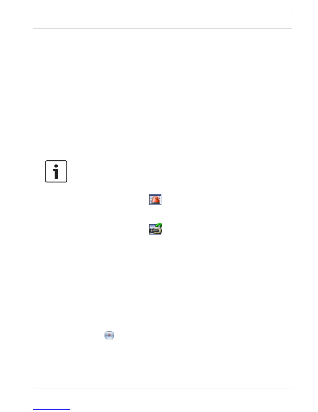
To display the Alarm Image window:
4 In an Image window, click .
The Alarm Image window is displayed.
To display the Image window again:
4 In an Image window, click
.
Live Mode or Playback Mode is displayed depending on the Mode that was displayed
before.
Starting manual recording
Main window
You can start recording for each camera manually. The quality level of alarm recording mode is
used. The duration of alarm recording is configured in the Configuration Client.
If the selected camera is already recording, the quality level is changed to alarm recording
mode. The alarm recording can be protected when NVR recording is used. With VRM
recording, the alarm recording is not protected.
Note: You cannot start manual recording for a DiBos camera.
To start recording:
1. Select an Image pane displaying a camera.
2. Click
.
Recording is started.
6.5
6.6
6.7
Bosch Video Management System Displaying camera images | en 27
Bosch Sicherheitssysteme GmbH Operator's Manual 2013.07 | V1 | Operator Client

Notes:
NVR recordings only: The icon in the Image pane bar changes to . Click to stop
recording. If you do not click to stop recording, manual recording stops after the configured
manual recording time. In the Timeline of the camera, the manual recording is displayed as
alarm recording.
VRM recordings only: You cannot manually stop recording. The recording stops after the
configured alarm recording time. In the Timeline of the camera, the pre-alarm recording is
displayed as alarm recording, if pre-alarm recording is configured in Configuration Client.
Starting a pre-configured camera sequence
Main window
With a camera sequence, a group of cameras are displayed one after the other. The preconfigured camera sequences are configured in the Configuration Client and appear in the
Logical Tree.
A sequence can be configured to use more than one Image pane. If there are not enough
Image panes to display the whole sequence, only those Image panes are displayed which fit
into the Image window. The remaining Image panes are not displayed and an appropriate
message is displayed.
Under the following conditions, a sequence is not being displayed:
– Video loss
– Connection to the camera lost
– No permission to display the camera
– Camera not configured
In addition, for sequences displayed on an analog monitor via a decoder, DiBos cameras
cannot be displayed.
Notice!
When the configuration is changed and activated, a camera sequence (pre-configured or
automatic) usually is continued after restart of the Operator Client.
But in the following cases the sequence is not continued:
A monitor where the sequence is configured to be displayed has been removed.
The mode of a monitor (single/quad view) where the sequence is configured to be displayed
has been changed.
The logical number of a monitor where the sequence is configured to be displayed is
changed.
To start and control a camera sequence:
1. Drag the required sequence from the Logical Tree window to an Image pane.
The sequence is displayed indicated by the symbol.
2. Click a playback control icon of the Image window toolbar to control the sequence.
Starting an automatic camera sequence
Main window
With a camera sequence, a group of cameras are displayed one after the other.
You configure the dwell time for these sequences in the Options dialog box (Extras menu,
Options... command).
Under the following conditions, a sequence is not being displayed:
6.8
6.9
28 en | Displaying camera images Bosch Video Management System
2013.07 | V1 | Operator Client Operator's Manual Bosch Sicherheitssysteme GmbH

– Video loss
– Connection to the camera lost
– No permission to display the camera
– Camera not configured
In addition, for sequences displayed on an analog monitor via a decoder, DiBos cameras
cannot be displayed.
Notice!
When the configuration is changed and activated, a camera sequence (pre-configured or
automatic) usually is continued after restart of the Operator Client.
But in the following cases the sequence is not continued:
A monitor where the sequence is configured to be displayed has been removed.
The mode of a monitor (single/quad view) where the sequence is configured to be displayed
has been changed.
The logical number of a monitor where the sequence is configured to be displayed is
changed.
To start a camera sequence:
1. Select an Image pane where you want the sequence to be played.
2. Right-click a folder in the Logical Tree or Favorites Tree window and click Show as
sequence in selected Image pane.
The cameras of the selected folder are displayed one after the other in the selected
Image pane.
indicates that the sequence is running.
To pause a camera sequence:
4 In the Image window toolbar, click .
The sequence stops playing, as indicated by .
To jump to the previous / next step of a camera sequence:
4 In the Image window toolbar, click or .
The sequence jumps to the previous or next step.
Using one channel audio mode
Main window
You use one channel audio mode when you want to hear only one audio source assigned to a
camera. You cannot activate audio for another camera.
To activate / de-activate multichannel audio mode:
1. On the Extras menu, click Options....
2. Select the Playback audio of the selected Image pane check box.
Using multichannel audio mode
Main window
You use multichannel audio mode when you want to hear different audio sources at the same
time. You can activate different audio sources assigned to a camera in the Image pane of each
camera.
To activate / de-activate multichannel audio mode:
1. On the Extras menu, click Options....
2. Select the Multichannel audio playback check box.
6.10
6.11
Bosch Video Management System Displaying camera images | en 29
Bosch Sicherheitssysteme GmbH Operator's Manual 2013.07 | V1 | Operator Client

Using digital zoom
Main window
Every Image pane provides a digital zoom function. This digital zoom has 11 levels: 1x, 1.35x,
1.8x, 2.5x, 3.3x, 4.5x, 6x, 8.2x, 11x, 14.9x, 20.1x.
When you save a Favorites View, the current setting of the digital zoom and the image section
are saved.
When you click
, the current setting of the digital zoom and the image section are used
for instant playback.
When Operator Client restarts, the current setting of the digital zoom and the image section
are retained.
To use digital zoom:
1. Right-click anywhere on an Image pane and click Zoom in.
indicates that the digital zoom was used.
2. Repeat the previous step to zoom in.
3. Drag the image to navigate to the desired image section.
4. Right-click the Image pane and click Zoom 1:1 to return to the original size.
disappears.
Note:
You can also use the controls for digital zoom in the PTZ Control window.
Saving a single image
Main window
To save a single image:
1. Select an Image pane.
2. Click
.
A dialog box for saving the image file is displayed.
3. Select the desired directory, enter a file name, and select the desired file type. JPG and
BMP are available.
4. Click OK.
The image is saved. The file contains additional information about the camera.
If you logged on to an Enterprise Management Server, the camera name is displayed with
the name of this camera’s Management Server as a prefix.
Printing a single image
Main window
To print a single image:
1. Select an Image pane.
2. Click
.
A dialog box for selecting the printer is displayed.
3. Click OK.
The image is printed. The printout contains additional information about the camera.
If you logged on to an Enterprise Management Server, the camera name is displayed with
the name of this camera’s Management Server as a prefix.
6.12
6.13
6.14
30 en | Displaying camera images Bosch Video Management System
2013.07 | V1 | Operator Client Operator's Manual Bosch Sicherheitssysteme GmbH
 Loading...