

Bosch VIDEOJET multi 4000, VJM-4016 Installation Manual
VIDEOJET multi 4000
VJM-4016
en Installation Manual


Table of contents
1
Safety 5
1.1 Electric shock hazard 5
1.2 Installation and operation 5
1.3 Maintenance and repair 6
2
Short information 7
2.1 About this manual 7
2.2 Conventions in this manual 7
2.3 Intended use 7
2.4 EU Directives 7
2.5 Rating plate 7
3
System overview 8
3.1 Parts included 8
3.2 System requirements 8
3.3 Overview of functions 8
3.4 Connections, controls and displays 11
3.4.1 Front view 11
3.4.2 Rear view 12
4
Installation 13
4.1 Preparations 13
4.2 Installing in a switch cabinet 13
5
Connection 15
5.1 Connecting cameras 15
5.2 Establishing the network connection 16
5.3 Connecting audio 17
5.4 Connecting alarm inputs and relay output 18
5.5 Creating a serial connection 19
5.6 Power on/power off 20
6
Configuration 21
6.1 Setup 21
6.2 Setup using Video Client 21
7
Troubleshooting 23
7.1 Contact 23
7.2 General malfunctions 23
7.3 Malfunctions with iSCSI connections 24
7.4 LEDs 24
7.5 Processor load 25
7.6 Network connection 25
7.7 Terminal block 25
7.8 Copyrights 26
8
Maintenance 27
8.1 Updates 27
8.2 Factory reset 27
8.3 Repairs 27
9
Decommissioning 28
9.1 Transfer 28
9.2 Disposal 28
VIDEOJET multi 4000 Table of Contents | en 3
Bosch Sicherheitssysteme GmbH Installation Manual 2014.02 | V1 | F.01U.298.750

10
Technical data 29
10.1 Electrical 29
10.2 Mechanical 29
10.3 Environmental conditions 29
10.4 Standards 29
4 en | Table of Contents VIDEOJET multi 4000
2014.02 | V1 | F.01U.298.750 Installation Manual Bosch Sicherheitssysteme GmbH

Safety
Electric shock hazard
– Never attempt to connect the unit to any power network other than the type for which it
is intended.
– Connect the unit to an earthed mains socket-outlet.
– Never open the housing.
– If a fault occurs, disconnect the unit from the power supply and from all other units.
– Install the unit only in a dry, weather-protected location.
– When installing in a switch cabinet, ensure that the unit has sufficient grounding.
– If safe operation of the unit cannot be ensured, remove it from service and secure it to
prevent unauthorized operation. In such cases, have the unit checked by Bosch Security
Systems.
Safe operation is no longer possible in the following cases:
– if there is visible damage to the unit or power cables,
– if the unit no longer operates correctly,
– if the unit has been exposed to rain or moisture,
– if foreign bodies have penetrated the unit,
– after long storage under adverse conditions, or
– after exposure to extreme stress in transit.
Viktige sikkerhetsinstruksjoner (Norway only)
Utstyr som er koplet til beskyttelsesjord via nettplugg og/eller via annet jordtilkoplet utstyr –
og er tilkoplet et kabel-TV nett, kan forårsake brannfare. For å unngå dette skal det ved
tilkopling av utstyret til kabel-TV nettet installeres en galvanisk isolator mellom utstyret og
kabel-TV nettet.
Viktiga säkerhetsinstruktioner (Sweden only)
Utrustning som är kopplad till skyddsjord via jordat vägguttag och/eller via annan utrustning
och samtidigt är kopplad till kabel-TV nät kan i vissa fall medfőra risk főr brand. Főr att undvika
detta skall vid anslutning av utrustningen till kabel-TVnät galvanisk isolator finnas mellan
utrustningen och kabel-TV nätet.
Installation and operation
– The relevant electrical engineering regulations and guidelines must be complied with at
all times during installation.
– Relevant knowledge of network technology is required to install the unit.
– Before installing or operating the unit, make sure you have read and understood the
documentation for the other equipment connected to it, such as cameras. The
documentation contains important safety instructions and information about permitted
uses.
– Perform only the installation and operation steps described in this manual. Any other
actions may lead to personal injury, damage to property or damage to the equipment.
Please ensure the following installation conditions:
– Do not install the unit close to heaters or other heat sources. Avoid locations exposed to
direct sunlight.
– Allow sufficient space for running cables.
– Ensure that the unit has adequate ventilation. Bear the total heat output in mind,
particularly when installing multiple units in a switch cabinet.
1
1.1
1.2
VIDEOJET multi 4000 Safety | en 5
Bosch Sicherheitssysteme GmbH Installation Manual 2014.02 | V1 | F.01U.298.750

– When making connections, use only the cables supplied or use appropriate cables
immune to electromagnetic interference.
– Position and run all cables so that they are protected from damage, and provide adequate
cable strain relief where needed.
– When installing in a switch cabinet, ensure that the screw joints are free of tension and
subject to as little mechanical stress as possible. Ensure that the unit has sufficient
grounding.
Maintenance and repair
– Never open the housing of the unit. The unit does not contain any user-serviceable parts.
– Ensure that all maintenance or repair work is carried out only by qualified personnel
(electrical engineers or network technology specialists). In case of doubt, contact your
dealer's technical service center.
1.3
6 en | Safety VIDEOJET multi 4000
2014.02 | V1 | F.01U.298.750 Installation Manual Bosch Sicherheitssysteme GmbH
Short information
About this manual
This manual is intended for persons responsible for the installation and operation of the
VIDEOJET multi 4000 encoder. International, national and any regional electrical engineering
regulations must be followed at all times. Relevant knowledge of network technology is
required. The manual describes the installation of the unit.
Conventions in this manual
In this manual, the following symbols and notations are used to draw attention to special
situations:
!
Warning!
Use of this signal word and symbol indicates that failure to follow the safety instructions
described may endanger persons. It indicates a hazardous situation which, if not avoided,
could result in death or serious injury.
!
Caution!
Use of this signal word and symbol indicates that failure to follow the safety instructions
described may endanger persons. It indicates a hazardous situation which, if not avoided,
could result in minor or moderate injury.
Notice!
Use of this signal word and symbol indicates that failure to follow the safety instructions
described may cause damage to the unit or other equipment or may lead to data loss.
Intended use
The VIDEOJET multi 4000 encoder transfers video, audio, and control signals over data
networks (Ethernet LAN, Internet). The unit is intended for use with CCTV systems. Various
functions can be triggered automatically by incorporating external alarm sensors. Other
applications are not permitted.
In the event of questions concerning the use of the unit which are not answered in this
manual, please contact your sales partner or:
Bosch Sicherheitssysteme GmbH
Robert-Bosch-Ring 5
85630 Grasbrunn
Germany
www.boschsecurity.com
EU Directives
The VIDEOJET multi 4000 encoder complies with the requirements of EU Directives 89/336
(Electromagnetic Compatibility) and 73/23, amended by 93/68 (Low Voltage Directive).
Rating plate
For exact identification, the model name and serial number are inscribed on the bottom of the
housing. Please make a note of this information before installation, if necessary, so as to have
it to hand in case of questions or when ordering spare parts.
2
2.1
2.2
2.3
2.4
2.5
VIDEOJET multi 4000 Short information | en 7
Bosch Sicherheitssysteme GmbH Installation Manual 2014.02 | V1 | F.01U.298.750
System overview
Parts included
– 1 VIDEOJET multi 4000 video encoder
– 1 accessory bag
– 1 Installation Manual
– optional: 1 power cord (depending on the ordered product package)
Notice!
Check that the delivery is complete and in perfect condition. Arrange for the unit to be
checked by Bosch Security Systems if you find any damage.
System requirements
General requirements
– Computer with Windows XP or Windows 7 operating system
– Network access (Intranet or Internet)
– Screen resolution at least 1,024 × 768 pixels
– 16- or 32-bit color depth
– Installed Oracle JVM
Note:
The Web browser must be configured to enable cookies to be set from the IP address of the
unit.
In Windows 7, deactivate protected mode on the Security tab under Internet Options.
You can find notes on using Microsoft Internet Explorer in the online Help in Internet Explorer.
Additional configuration and operational requirements
You find the information on additional configuration and operational requirements in the
Releaseletter document for the respective firmware.
For the latest version of the firmware, required programs and controls, and the current version
of the Video Client management software, access your Bosch product catalog on the Internet.
Overview of functions
Network video server
The VIDEOJET multi 4000 encoder is a compact network video server for 16 connected video
sources. It is primarily designed for encoding video, audio and control data for transfer over an
IP network. With its encoding in the H.264 format, the unit is ideally suited for making existing
analog CCTV cameras IP-compatible and for remote access to digital VCRs and multiplexers.
The use of existing networks means that integration with CCTV systems or local networks can
be achieved quickly and easily.
Video images from a single sender can be received simultaneously on multiple receivers. Audio
signals can also be transmitted from and to compatible units.
Dual Streaming
The encoder uses the feature Dual Streaming to generate two independent IP video streams
per channel, both at full 4CIF resolution and with full frame rate.
Video encoding
The VIDEOJET multi 4000 High Profile encoder uses the H.264 video compression standard.
Thanks to efficient encoding, the data rate remains low even with high image quality and can
also be adapted to local conditions within wide limits.
3
3.1
3.2
3.3
8 en | System overview VIDEOJET multi 4000
2014.02 | V1 | F.01U.298.750 Installation Manual Bosch Sicherheitssysteme GmbH

Audio encoding
The VIDEOJET multi 4000 encoder uses the G.711, AAC, and L16 audio compression
standards. G.711 is the default setting for live transmission. For recording the default setting
is AAC. When configuring with a Web browser, you can select your preferred standard for
recording. Using video management systems, this is also true for live audio.
Viewing
View the encoder video on a PC using a Web browser, in Bosch Video Management System, or
integrate it into another video management system. By routing the IP video to a highperformance VIDEOJET decoder or to Monitor Wall, you can present the video with ultimate
clarity.
Recording
You can record each video input independently on different media. Thus video can be
recorded centrally on iSCSI drives managed by VRM.
The encoder features a highly flexible recording scheduler, providing up to ten programmable
recording profiles and allowing individually assigned camera profiles. With these profiles, you
can accelerate the frame rate as well as increase the quality on alarm, saving recording space
during non-alarm periods.
Multicast
In suitably configured networks, the multicast function enables simultaneous real-time video
transmission to multiple receivers. The UDP and IGMP V2 protocols must be implemented on
the network for this function.
Access security
The encoder offers various security levels for accessing the network, the unit, and the data
channels. As well as password protection with up to three levels, they support 802.1x
authentication using a RADIUS server for identification. You can secure Web browser access
by HTTPS using an SSL certificate that is stored in the unit. For total data protection, each
communication channel—video, audio, or serial I/O—can be independently AES encrypted.
Remote control
For remote control of external units such as pan or tilt heads for cameras or motorized zoom
lenses, control data is transmitted via the encoder's bidirectional serial interface. This
interface can also be used to transmit transparent data.
Intelligence
The encoder comes with built-in MOTION+ video motion detection. This motion detection
algorithm is based on pixel change and includes object size filtering capabilities.
On alarm, the device can send an e‑mail with JPEG images attached.
ONVIF conformance
Conformance to ONVIF 1.02 and ONVIF Profile S provides interoperability between network
video products regardless of manufacturer. In addition, the firmware of the device supports all
applicable features of the ONVIF 2.2 specification.
ONVIF conformant devices are able to exchange live video, audio, metadata, and control
information and ensure that they are automatically discovered and connected to network
applications such as video management systems.
VIDEOJET multi 4000
System overview | en 9
Bosch Sicherheitssysteme GmbH Installation Manual 2014.02 | V1 | F.01U.298.750

Summary
The VIDEOJET multi 4000 encoder provides the following main functions:
– Video, audio, and data transmission over IP data networks
– Dual Streaming function for the encoder for simultaneous encoding with two individually
definable profiles
– Multicast function for simultaneous image transmission to multiple receivers
– 16 analog BNC composite video inputs (PAL/NTSC)
– Video encoding according to international standard H.264
– Deinterlacing at video input and progressive encoding
– Integrated Ethernet port (10/100/1000 Base-T)
– Network-attached iSCSI recording
– Transparent, bidirectional data channel via RS-232/RS-422/RS-485 serial interface
– Configuration and remote control of all internal functions via TCP/IP, also secured via
HTTPS
– Password protection to prevent unauthorized connection or configuration changes
– 4 alarm inputs for external sensors (such as door contacts)
– 1 relay output for switching external units (such as lamps or sirens)
– Built-in video sensor for motion alarms
– Event-controlled automatic connection
– Convenient maintenance via uploads
– Flexible encryption of control and data channels
– Authentication according to international standard 802.1x
– Bidirectional audio (mono) for line connections
– Audio encoding according to international standards AAC, G.711, and L16
10
en | System overview VIDEOJET multi 4000
2014.02 | V1 | F.01U.298.750 Installation Manual Bosch Sicherheitssysteme GmbH
Connections, controls and displays
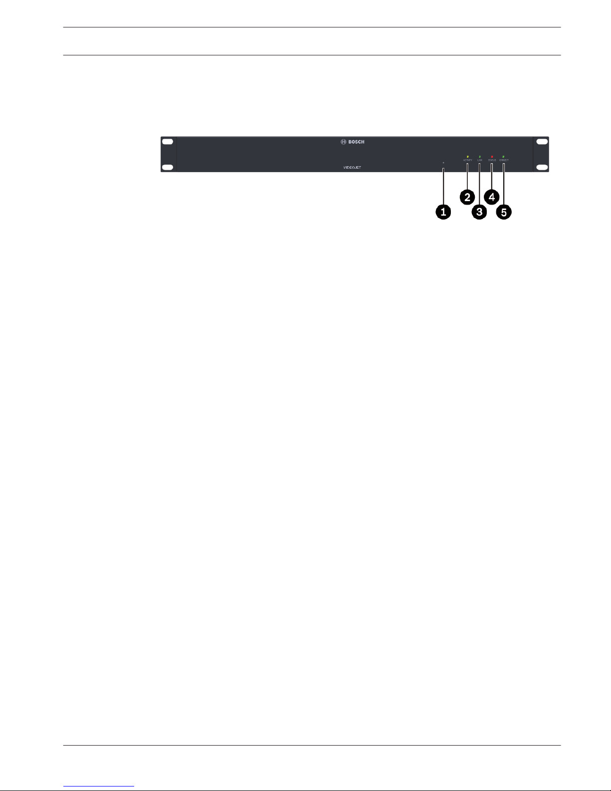
Front view
1 Factory reset button
to restore factory default settings
2 LED ACTIVITY
flashes during data transmission
3 LED LINK
lights up when the unit is connected to the network
4 LED STATUS
lights up during startup
5 LED CONNECT
lights up when supplied with power after startup
See also
– LEDs, page 24
3.4
3.4.1
VIDEOJET multi 4000 System overview | en 11
Bosch Sicherheitssysteme GmbH Installation Manual 2014.02 | V1 | F.01U.298.750
 Loading...