

Bosch VJC-7000-90, VIDEOJET connect 7000 Operation Manual
VIDEOJET connect 7000
VJC-7000-90
en Operation Manual


Table of contents
1
Safety 7
1.1 About this Manual 7
1.2 Legal Information 7
1.3 Safety Precautions 7
1.4 Important Safety Instructions 8
1.5 Important Notices 10
1.6 Customer Support and Service 11
2
Unpacking 12
2.1 Parts List 12
2.2 Additional Tools Required 12
2.3 Additional Hardware Required 12
2.4 Optional Accessories 12
3
Product Overview 13
3.1 Typical Configuration - Basic 14
3.2 Typical Configuration - Daisy Chain 15
3.3 Typical Configuration - Multiple Cameras to Head-end Network 16
3.4 Typical Configuration - Mobile Viewing 17
4
Technical Data 18
4.1 Specifications 18
4.2 Dimensional Drawing 19
5
Installation 20
5.1 Mounting 20
5.2 Conduit Installation 22
5.3 PCBA Connections 23
5.4 Power Cable Installation 24
5.5 Ethernet Cables Installation 24
5.6 Fiber Installation 24
5.7 Alarm Inputs 25
5.8 Alarm Outputs 25
5.9 Washer Pump 25
5.10 Audio In and Out 26
5.11 Local Storage Media (CF Card) 26
5.12 Final Steps 26
6
Control of Connected Devices 27
6.1 System Requirements 27
6.2 Configuration Overview 28
7
General settings 29
7.1 Identification 29
7.1.1 Naming 29
7.1.2 ID 29
7.1.3 iSCSI Initiator extension 29
7.2 Password 29
7.2.1 Enter Password 30
7.2.2 Confirm password 30
7.3 Date/Time 30
7.3.1 Date format 30
7.3.2 Device date / Device time 30
VIDEOJET connect 7000 Table of Contents | en 3
Bosch Security Systems Operation Manual 2014.10 | 1.4 | F.01U.291.524

7.3.3 Device time zone 30
7.3.4 Daylight saving time 30
7.3.5 Time server IP address 31
7.3.6 Time server type 31
8
Web Interface 32
8.1 Appearance 32
8.1.1 Website language 32
8.1.2 Company logo 32
8.1.3 Device logo 32
8.1.4 Show VCA metadata 32
8.1.5 Show VCA trajectories 32
8.1.6 Show overlay icons 32
8.1.7 Select video player 32
8.1.8 JPEG size, interval and quality 32
8.2 LIVE Functions 32
8.2.1 Transmit audio 33
8.2.2 Show alarm inputs 33
8.2.3 Show alarm outputs 33
8.2.4 Show event log 33
8.2.5 Show system log 33
8.3 Logging 33
8.3.1 Save event log 33
8.3.2 Save system log 33
9
Transcoder 34
9.1 Transcoder Setup 34
9.1.1 Device [number] 34
9.1.2 Name 34
9.1.3 Password 34
9.1.4 Http port, Https port 34
9.1.5 Configure Router 34
9.2 Transcoder Profile 35
9.2.1 Profile name 35
9.2.2 Maximum bit rate 35
9.2.3 Transcoding interval 36
9.2.4 Video resolution 36
9.2.5 I-frame distance 36
9.2.6 Min. P-frame QP 36
9.2.7 I/P-frame delta QP 36
9.3 Audio 37
10
Recording 38
10.1 Storage Management 38
10.1.1 Device manager 38
10.1.2 Recording media 38
10.1.3 Activating and configuring storage media 39
10.1.4 Formatting storage media 39
10.1.5 Deactivating storage media 39
10.2 Remote Video Device 39
10.2.1 Status 39
10.2.2 Last error 39
4 en | Table of Contents VIDEOJET connect 7000
2014.10 | 1.4 | F.01U.291.524 Operation Manual Bosch Security Systems

10.2.3 Recording target 39
10.2.4 Bit rate 40
10.2.5 Initialize Recording 40
10.2.6 Start Recording 40
10.2.7 Stop Recording 40
11
Alarm 41
11.1 Alarm Task Editor 41
12
Network 42
12.1 Network Access 42
12.1.1 Automatic IP assignment 42
12.1.2 IP V4 address 42
12.1.3 IP V6 address 42
12.1.4 DNS server address 42
12.1.5 Video transmission 42
12.1.6 HTTP browser port 43
12.1.7 HTTPS browser port 43
12.1.8 RCP+ port 1756 43
12.1.9 Telnet support 43
12.1.10 Interface mode PoE 43
12.1.11 Interface mode ETH 1 43
12.1.12 Interface mode ETH 2 44
12.1.13 Network MSS [Byte] 44
12.1.14 iSCSI MSS [Byte] 44
12.1.15 Network MTU [Byte] 44
12.2 DynDNS 44
12.2.1 Enable DynDNS 44
12.2.2 Provider 44
12.2.3 Host name 44
12.2.4 User name 44
12.2.5 Password 44
12.2.6 Force registration now 45
12.2.7 Status 45
12.3 Advanced 45
12.3.1 Cloud-based Services 45
12.3.2 RTSP port 45
12.3.3 Authentication (802.1x) 45
12.4 Network Management 45
12.4.1 SNMP 45
12.4.2 UPnP 46
12.4.3 Quality of Service 46
12.5 Accounts 46
12.6 IPv4 Filter 46
12.7 Encryption 47
13
Service 48
13.1 Installer Menu 48
13.1.1 Reboot device 48
13.1.2 Factory defaults 48
13.2 Maintenance 48
13.2.1 Update server 48
VIDEOJET connect 7000 Table of Contents | en 5
Bosch Security Systems Operation Manual 2014.10 | 1.4 | F.01U.291.524

13.2.2 Firmware 48
13.2.3 Upload History 49
13.2.4 Configuration 49
13.2.5 Maintenance log 49
13.3 Licenses 49
13.4 System Overview 49
14
Operation via the browser 50
14.1 Live page 50
14.1.1 LIVE page overview 50
14.1.2 Digital I/O 50
14.1.3 System Log / Event Log 50
14.1.4 Recording status 50
14.1.5 Storage, CPU and network status 50
14.1.6 Status icons 51
14.1.7 IP Address of Connected Devices 51
14.2 Playback 51
14.2.1 Selecting recordings for playback 52
14.2.2 Exporting tracks 52
14.2.3 Searching for tracks 52
14.2.4 Controlling playback 52
15
Configure VIDEOJET connect 7000 to Operate with a MIC7000 Camera 54
15.1 Configure Alarm Inputs and Outputs 54
15.2 Configure Audio 54
15.3 Configure Video Playback 54
16
Troubleshooting and Maintenance 55
16.1 Troubleshooting 55
16.2 Maintenance 55
17
Technical data 57
6 en | Table of Contents VIDEOJET connect 7000
2014.10 | 1.4 | F.01U.291.524 Operation Manual Bosch Security Systems
Safety
About this Manual
This manual has been compiled with great care and the information it contains has been
thoroughly verified. The text was complete and correct at the time of printing. Because of the
ongoing development of products, the content of the manual may change without notice.
Bosch Security Systems accepts no liability for damage resulting directly or indirectly from
faults, incompleteness, or discrepancies between the manual and the product described.
Legal Information
Copyright
This manual is the intellectual property of Bosch Security Systems, Inc. and is protected by
copyright. All rights reserved.
Trademarks
All hardware and software product names used in this document are likely to be registered
trademarks and must be treated accordingly.
Safety Precautions
In this manual, the following symbols and notations are used to draw attention to special
situations:
Danger!
High risk: This symbol indicates an imminently hazardous situation such as “Dangerous
Voltage” inside the product. If not avoided, this will result in an electrical shock, serious bodily
injury, or death.
!
Caution!
Medium risk: Indicates a potentially hazardous situation. If not avoided, this may result in
minor or moderate injury. Alerts the user to important instructions accompanying the unit.
!
Caution!
Low risk: Indicates a potentially hazardous situation. If not avoided, this may result in
property damage or risk of damage to the unit.
Notice!
This symbol indicates information or a company policy that relates directly or indirectly to the
safety of personnel or protection of property.
1
1.1
1.2
1.3
VIDEOJET connect 7000 Safety | en 7
Bosch Security Systems Operation Manual 2014.10 | 1.4 | F.01U.291.524

Important Safety Instructions
Attachments - Use only attachments/accessories specified by the manufacturer. Any change
or modification of the equipment, not expressly approved by Bosch, could void the user's
warranty or authorization agreement.
Cleaning - Unplug the device before cleaning. Generally, using a dry cloth for cleaning is
sufficient, but a moist, fluff-free cloth may also be used. Do not use liquid cleaners or aerosol
cleaners.
Damage requiring service – Unplug the devices from the main AC power source and refer
servicing to qualified service personnel whenever any damage to the device has occurred,
such as:
- the power supply cable is damaged;
- an object has fallen on the device;
- the device has been dropped, or its enclosure has been damaged;
- the device does not operate normally when the user follows the operating instructions
correctly.
Electrostatic-sensitive device - Use proper CMOS/MOS-FET handling precautions to avoid
electrostatic discharge. NOTE: Wear required grounded wrist straps and observe proper ESD
safety precautions when handling the electrostatic-sensitive printed circuit boards.
Grounding:
- Connect outdoor equipment to the unit's inputs only after this unit has had its ground
terminal connected properly to a ground source.
- Disconnect the unit's input connectors from outdoor equipment before disconnecting the
grounding terminal.
- Follow proper safety precautions such as grounding for any outdoor device connected to this
unit.
U.S.A. models only - Section 810 of the National Electrical Code, ANSI/NFPA No.70, provides
information regarding proper grounding of the mount and supporting structure, size of
grounding conductors, location of discharge unit, connection to grounding electrodes, and
requirements for the grounding electrode.
Heat sources - Do not install unit near any heat sources such as radiators, heaters, or other
equipment (including amplifiers) that produce heat.
Installation location - The unit is intended only for installation in a Restricted Access Location.
Lightning – For added protection during a lightning storm, or when leaving the device
unattended and unused for long periods, unplug the device and disconnect the cable system.
This will prevent damage to the device from lightning and power line surges.
Object and liquid entry – Never push objects of any kind into the device through openings, as
the objects may touch dangerous voltage points or short-out parts that could result in a fire or
electrical shock. Never spill or pour liquid of any kind on or into the device. Do not place
objects filled with liquids, such as vases or cups, on the device.
Outdoor signals - The installation for outdoor signals, especially regarding clearance from
power and lightning conductors and transient protection, must be in accordance with NEC725
and NEC800 (CEC Rule 16-224 and CEC Section 60).
Overvoltage – Installation category (also called Overvoltage Category) specifies the level of
mains voltage surges that the equipment will be subjected to. The category depends upon the
location of the equipment, and on any external surge protection provided. Equipment in an
industrial environment, directly connected to major feeders/short branch circuits, is subjected
to Installation Category III. If this is the case, a reduction to Installation Category II is required.
This can be achieved by use of an isolating transformer with an earthed screen between
1.4
8 en | Safety VIDEOJET connect 7000
2014.10 | 1.4 | F.01U.291.524 Operation Manual Bosch Security Systems
primary and secondary, or by fitting listed Surge Protective Devices (SPDs) from live to neutral
and from neutral to earth. Listed SPDs shall be designed for repeated limiting of transient
voltage surges, suitable rated for operating voltage and designated as follows:
- Type 2 (Permanently connected SPDs intended for installation on the load side of the service
equipment overcurrent device)
- Nominal Discharge Current (In) 20 kA min.
For example: FERRAZ SHAWMUT, STT2240SPG-CN, STT2BL240SPG-CN rated 120/240 VAC,
(In=20 kA)
Power disconnect - An appropriate disconnect device shall be provided external to the
equipment.
Power sources - Use only the power source indicated in this manual/on the device label.
Ensure that the rating of current of the supply cable is adequate for the device. Before
proceeding, disconnect the power from the cable to be installed into the device.
- For external-power-supplied devices, use only the recommended or approved power
supplies.
- For limited power source devices, this power source must comply with EN 60950.
Substitutions may damage the device or cause fire or shock.
- For 24 VAC devices, voltage applied to the device’s power input should not exceed ±10% (or
28 VAC). User-supplied wiring must comply with local electrical codes (Class 2 power levels).
Do not ground the supply at the terminals or at the device’s power supply terminals.
- If unsure of the type of power supply to use, contact your dealer or local power company.
Replacement parts - Use only replacement parts specified by the manufacturer. Unauthorized
substitutions may cause fire, electrical shock, or other hazards.
Safety check – Safety checks should be performed upon completion of service or repairs to
the device to ensure proper operating condition.
Surge suppression - Use proper surge suppression on your network video, power, audio, and
alarm cables.
!
Warning!
Short-circuit (overcurrent) protection device required
This product relies on the building's installation for short-circuit (overcurrent) protection.
Ensure that the protective device is Listed rated not greater than: 20 A.
VIDEOJET connect 7000 Safety | en 9
Bosch Security Systems Operation Manual 2014.10 | 1.4 | F.01U.291.524
Important Notices
Notice!
This device is intended for use in public areas only.
U.S. federal law strictly prohibits surreptitious recording of oral communications.
Notice!
This is a class A product. In a domestic environment this product may cause radio
interference, in which case the user may be required to take adequate measures.
FCC & ICES Information
(U.S.A. and Canadian Models Only)
This device complies with part 15 of the FCC Rules. Operation is subject to the following
conditions:
– this device may not cause harmful interference, and
– this device must accept any interference received, including interference that may cause
undesired operation.
NOTE: This equipment has been tested and found to comply with the limits for a Class A
digital device, pursuant to Part 15 of the FCC Rules and ICES-003 of Industry Canada. These
limits are designed to provide reasonable protection against harmful interference when the
equipment is operated in a commercial environment. This equipment generates, uses, and
radiates radio frequency energy and, if not installed and used in accordance with the
instruction manual, may cause harmful interference to radio communications. Operation of
this equipment in a residential area is likely to cause harmful interference, in which case the
user will be required to correct the interference at his expense.
Intentional or unintentional modifications, not expressly approved by the party responsible for
compliance, shall not be made. Any such modifications could void the user's authority to
operate the equipment. If necessary, the user should consult the dealer or an experienced
radio/television technician for corrective action.
The user may find the following booklet, prepared by the Federal Communications
Commission, helpful: How to Identify and Resolve Radio-TV Interference Problems. This
booklet is available from the U.S. Government Printing Office, Washington, DC 20402, Stock
No. 004-000-00345-4.
UL Disclaimer
Underwriter Laboratories Inc. ("UL") has not tested the performance or reliability of the
security or signaling aspects of this product. UL has only tested fire, shock and/or casualty
hazards as outlined in Standard(s) for Safety for Information Technology Equipment, UL
60950-1 . UL Certification does not cover the performance or reliability of the security or
signaling aspects of this product.
UL MAKES NO REPRESENTATIONS, WARRANTIES, OR CERTIFICATIONS WHATSOEVER
REGARDING THE PERFORMANCE OR RELIABILITY OF ANY SECURITY OR SIGNALING-RELATED
FUNCTIONS OF THIS PRODUCT.
1.5
10 en | Safety VIDEOJET connect 7000
2014.10 | 1.4 | F.01U.291.524 Operation Manual Bosch Security Systems

Customer Support and Service
If this unit needs service, contact the nearest Bosch Security Systems Service Center for
authorization to return and shipping instructions.
Service Centers
USA
Telephone: 800-366-2283 or 585-340-4162
Fax: 800-366-1329
Email: cctv.repair@us.bosch.com
Customer Service
Telephone: 888-289-0096
Fax: 585-223-9180
Email: security.sales@us.bosch.com
Technical Support
Telephone: 800-326-1450
Fax: 585-223-3508 or 717-735-6560
Email: technical.support@us.bosch.com
Repair Center
Telephone: 585-421-4220
Fax: 585-223-9180 or 717-735-6561
Email: security.repair@us.bosch.com
Canada
Telephone: 514-738-2434
Fax: 514-738-8480
Europe, Middle East & Africa Region
Please contact your local distributor or Bosch sales office. Use this link:
http://www.boschsecurity.com/startpage/html/europe.htm
Asia Pacific Region
Please contact your local distributor or Bosch sales office. Use this link:
http://www.boschsecurity.com/startpage/html/asia_pacific.htm
More Information
For more information please contact the nearest Bosch Security Systems location or visit
www.boschsecurity.com
1.6
VIDEOJET connect 7000 Safety | en 11
Bosch Security Systems Operation Manual 2014.10 | 1.4 | F.01U.291.524

Unpacking
– This equipment should be unpacked and handled with care. Check the exterior of the
packaging for visible damage. If an item appears to have been damaged in shipment,
notify the shipper immediately.
– Verify that all the parts listed in the Parts List below are included. If any items are
missing, notify your Bosch Security Systems Sales or Customer Service Representative.
– Do not use this product if any component appears to be damaged. Please contact Bosch
Security Systems in the event of damaged goods.
– The original packing carton is the safest container in which to transport the unit and must
be used if returning the unit for service. Save it for possible future use.
Parts List
Each device ships with the following parts:
– One (1) VIDEOJET connect 7000 enclosure with three (3) M16 plugs, three (3) ¾”
blanking plugs, and five (5) M16 gland locknuts installed
– Parts bag with:
– one (1) terminal plug connector, 2-pin [for connections to optional washer]
– one (1) terminal plug connector, 3-pin [for AC mains power input]
– one (1) terminal plug connector, 6-pin [for alarm inputs]
– one (1) terminal plug connector, 7-pin [for alarm outputs and tamper switch]
– three (3) watertight M16 cable glands with O-rings
– Installation Manual
Additional Tools Required
Installers must provide the following items to complete installation of a MIC-ALM-WAS-24:
– Phillips-head screwdriver, M6, for the four (4) captive lid screws (M6 x 35), and for the
M6 mounting screws (if mounting is desired)
– Ring crimp tool (Davico type DHCR15 or equivalent)
Additional Hardware Required
– Four (4) M6 mounting screws and washers, if mounting is desired
– Power cable
– Ethernet cable (Cat5e/Cat6e rated to 350 MHz)
– Metal conduit suitable for containing cables external to the enclosure
Optional Accessories
– SFP-based fiber optic modules (1GB only) such as:
– Agilent, SFP-GE-SX-MM850-A HFBR5710LP 7
– Cisco, GLC-LH-SM 1300nm
– Cisco, GLC-SX-MM 850nm 8
– Finisar, FTLF8519P2BTL 850nm
2
2.1
2.2
2.3
2.4
12 en | Unpacking VIDEOJET connect 7000
2014.10 | 1.4 | F.01U.291.524 Operation Manual Bosch Security Systems
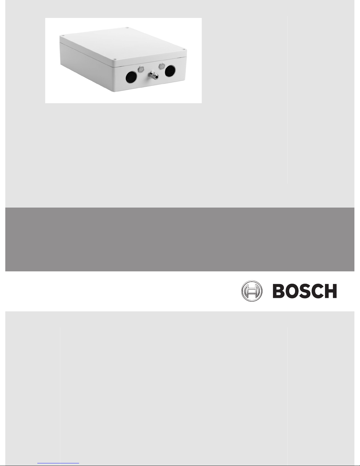
Product Overview
The device VIDEOJET connect 7000 (VJC-7000-90) is a full-featured network power supply
unit that can operate a variety of Bosch PTZ cameras such as MIC7000. The device includes
one (1) HPoE network connection, two (2) standard network interfaces for connections to
additional IP devices, one (1) local storage slot for a CompactFlash (CF) memory card, two (2)
slots for use with SFP-based fiber optic modules, alarm/washer control interfaces, and audio
I/O. Bosch transcoder technology provides seamless integration with Video Recording
Management (VRM) systems, enabling live video and recording/playback of scenes from
cameras connected to the device.
The device provides the following features:
– HD-Base T PoH dedicated for one RJ45 Ethernet connection between the device and a
Bosch IP camera powered by PoE/High PoE
– a push button on the PBCA to allow users to activate/test a connected washer pump
accessory (optional, user-supplied)
– Ability to control connected cameras using the built-in web browser of the device
– support for daisy chaining
Notice!
For full functionality, a MIC7000 camera connected to VIDEOJET connect 7000 requires
firmware version 5.93 or later. Download the firmware from
https://downloadstore.boschsecurity.com.
Note: To achieve a distance of 100 m (328 ft) using Cat5e/Cat6e cable, Bosch recommends
using cable with a minimum rating of 350 MHz.
3
VIDEOJET connect 7000 Product Overview | en 13
Bosch Security Systems Operation Manual 2014.10 | 1.4 | F.01U.291.524
Typical Configuration - Basic
Cat5e/Cat6e = 100 m max.
1
1
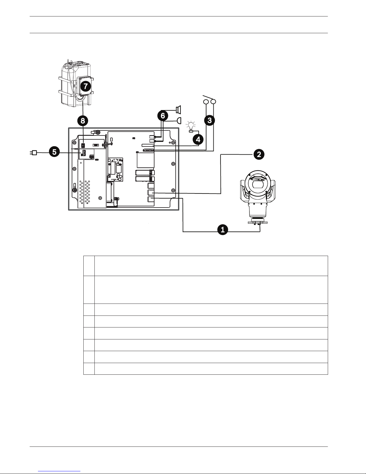
Figure 3.1: Basic configuration with VIDEOJET connect 7000
1 Ethernet (network) cable (Cat5e/Cat6e) (user-supplied) between a Bosch camera and
the port labeled PoE on VIDEOJET connect 7000
2 Data-only IP cable (Cat5e/Cat6e) to the head-end network
Note: The cable to the head-end also can be fiber optic cable from one of the two SFP
slots.
3 Alarm input / output interface cables (user-supplied)
4 Alarm output cables (user-supplied)
5 120 / 230 VAC, 50/60 Hz
6 Audio input / output interface cables (user-supplied)
7 External washer pump (user-supplied)
8 Washer output, 2-conductor (user-supplied)
3.1
14 en | Product Overview VIDEOJET connect 7000
2014.10 | 1.4 | F.01U.291.524 Operation Manual Bosch Security Systems
Typical Configuration - Daisy Chain
Cat5e/Cat6e = 100 m max.
1
1
Cat5e/Cat6e = 100 m max.
1
1
Cat5e/Cat6e = 100 m max.
1
1
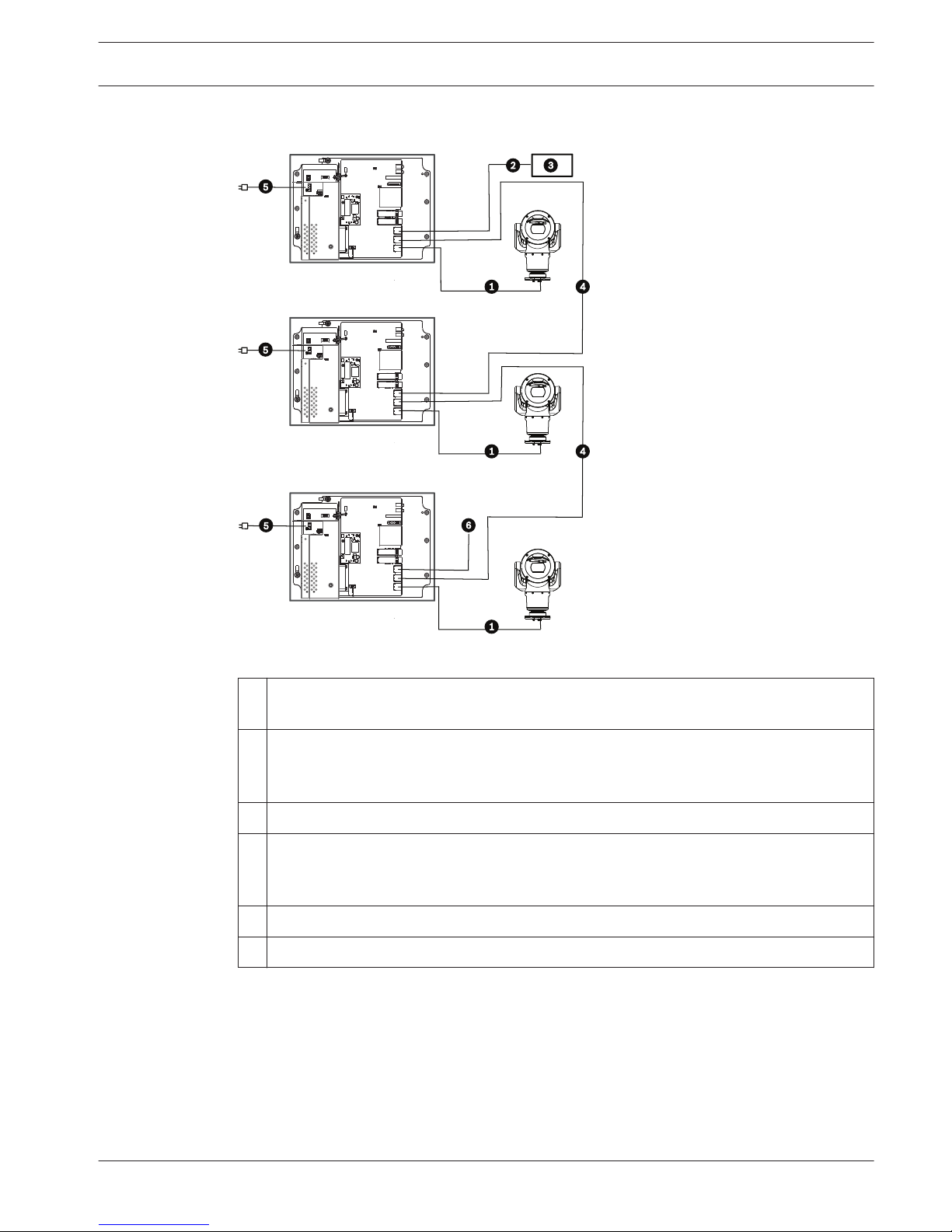
Figure 3.2: Typical daisy chain configuration for VIDEOJET connect 7000
1
Ethernet (network) cable (Cat5e/Cat6e) (user-supplied) between a Bosch camera and
the port labeled PoE on VIDEOJET connect 7000
2 Data-only IP cable (Cat5e/Cat6e) to the head-end network
Note: The cable to the head-end also can be fiber optic cable from one of the two SFP
slots.
3 Head-end network
4 “Daisy chain” Data-only IP cable
Note: The cable to the head-end also can be fiber optic cable from one of the two SFP
slots.
5 120 / 230 VAC, 50/60 Hz
6 “Daisy chain” Data-only IP cable to the next VIDEOJET connect 7000 unit (not shown)
3.2
VIDEOJET connect 7000 Product Overview | en 15
Bosch Security Systems Operation Manual 2014.10 | 1.4 | F.01U.291.524
Typical Configuration - Multiple Cameras to Head-end Network
Cat5e/Cat6e = 100 m max.
1
1
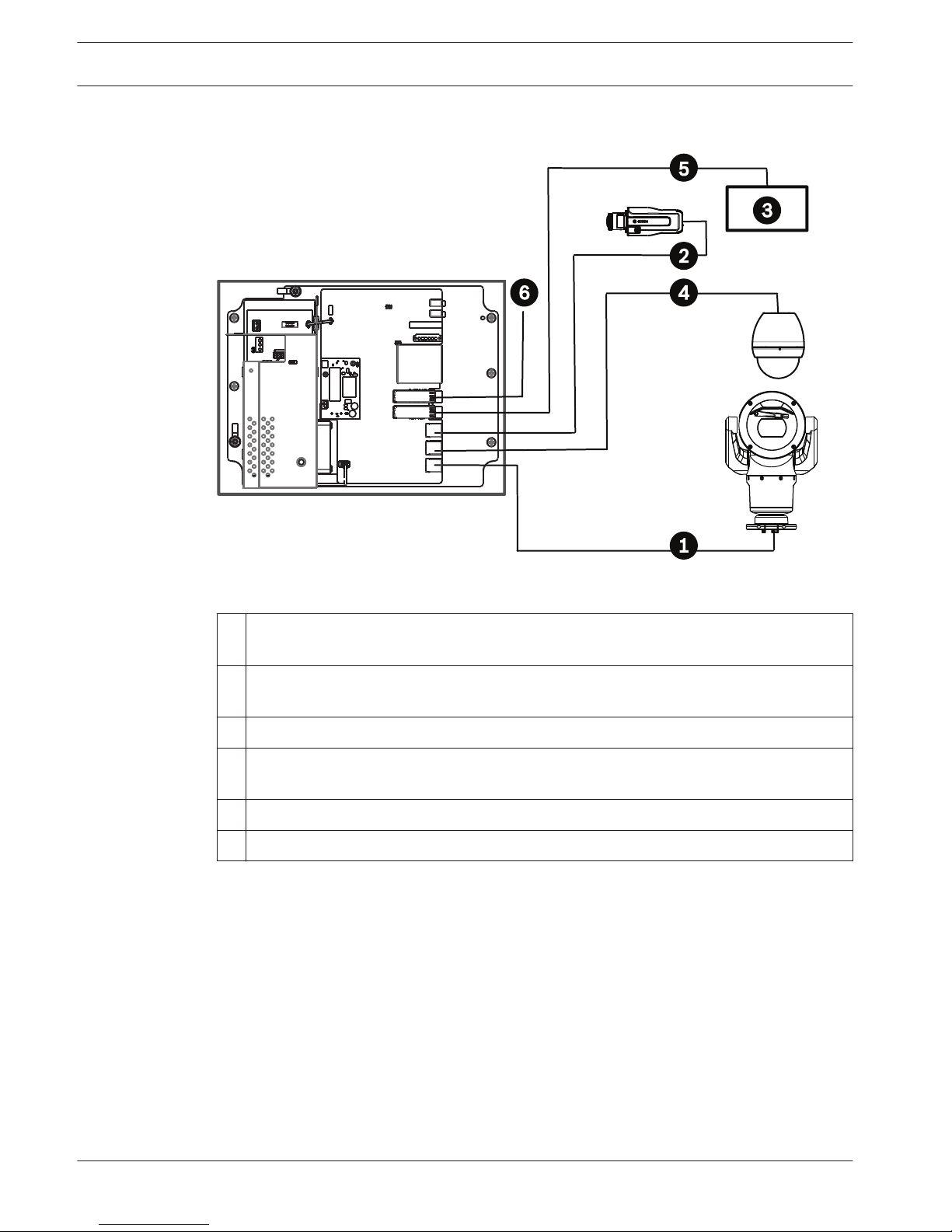
Figure 3.3: Multiple cameras to VIDEOJET connect 7000
1
Ethernet (network) cable (Cat5e/Cat6e) (user-supplied) between a Bosch camera and
the port labeled PoE on VIDEOJET connect 7000
2 Data-only IP cable (Cat5e/Cat6e) between a Bosch IP camera and the port labeled ETH 2
on VIDEOJET connect 7000
3 Head-end network
4 Data-only IP cable (Cat5e/Cat6e) between a Bosch camera and the port labeled ETH 1
on VIDEOJET connect 7000
5 Fiber optic cable to the head-end network
6 Fiber optic cable to the next VIDEOJET connect 7000unit (if applicable)
3.3
16 en | Product Overview VIDEOJET connect 7000
2014.10 | 1.4 | F.01U.291.524 Operation Manual Bosch Security Systems
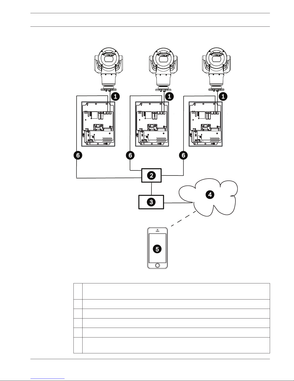
Typical Configuration - Mobile Viewing
Cat5e/Cat6e = 100 m max.
1
1
1
1
1
1
Figure 3.4: Mobile Viewing using the integrated Transcoder of VIDEOJET connect 7000
1
Ethernet (network) cable (Cat5e/Cat6e) (user-supplied) between a Bosch camera and
the port labeled PoE on VIDEOJET connect 7000
2 Network switch (user-supplied)
3 Head-end network
4 Internet (“the cloud”)
5 Mobile device with Bosch video security app
6 Data-only IP cable to the next VIDEOJET connect 7000 unit
Note: The cable also can be fiber optic cable from one of the two SFP slots.
3.4
VIDEOJET connect 7000 Product Overview | en 17
Bosch Security Systems Operation Manual 2014.10 | 1.4 | F.01U.291.524

Technical Data
Specifications
Specification Value
Power requirements 100 VAC - 240 VAC (90 VAC - 264 VAC with tolerance
considered), 50/60 Hz; 56V output
Alarm inputs Four (4) normal dry contacts (selectable N.O./N.C.)
One (1) monitored tamper alarm input, 2.2K ohm end-ofline termination
Alarm outputs Three (3) open collector outputs, 32 VDC, 150 mA
Audio One (1) mono line in; one (1) mono line out
connector 3.5 mm stereo jack
signal line in 9 kohm typical, 5.5 Vpp max. 25
signal line out 3.0 Vpp at 10 kohm typical;
2.3 Vpp at 32 ohm typical;
1.7 Vpp at 16 ohm typical
Washer driver output Dry contact relay, 250 V, 5 A
Communication Three (3) 10BASE-T/100BASE-TX/1000Base-TX
If SFP fiber optic modules installed: two (2) 1000 BASEFX
Push button Momentary switch to activate washer relay
Local storage One (1) slot for optional CompactFlash (CF) memory
card, Type I / Type II, 32 GB max (user-supplied)
SFP (small form-factor pluggable) Two (2) slots for use with SFP-based fiber optic modules
(1GB only) as recommended in the section Optional
Accessories, page 12
Ingress Protection Rating/
Standard
IP66, IP67, Type 4
4
4.1
18 en | Technical Data VIDEOJET connect 7000
2014.10 | 1.4 | F.01U.291.524 Operation Manual Bosch Security Systems
 Loading...