

Bosch VG5-7230-CPT5, VG5-7230-EPC5, VG5-7230-EPR5 Operation Manual
AUTODOME IP starlight 7000 HD
VG5-7230-CPT5 │ VG5-7230-EPC5 │ VG5-7230-EPR5
en
Operation Manual


AUTODOME IP starlight 7000 HD Table of contents | en 3
Bosch Security Systems Operation Manual 2016-07 | 1.0 | F.01U.283.679
Table of contents
1
Safety EN 7
1.1 About this Manual 7
1.2 Legal Information 7
1.3 Safety Precautions 7
1.4 Important Safety Instructions 7
1.5 Important Notices 9
1.6 Connection in Applications 12
1.7 Customer Support and Service 12
2
Unpacking 13
2.1 Parts List, Installation 13
2.2 Tools Required 14
2.3 Additional Products Required 17
3
System overview 18
4
Pre-installation Checklist 19
4.1 Stabilization 20
5
Installing the Optional SD Card 21
6
Mount Power Supply Box (Wall, Mast (Pole), and Corner Mounts) 22
7
Installing the Pendant Arm Wall, Corner, and Mast (Pole) Mounts 24
7.1 Description 24
7.2 Route Wires and Attach Connectors 24
7.3 Route Power through Intermediate Power Supply Box 28
7.4 Attach Pendant Arm to Power Supply Box 30
7.5 Make Connections in the Power Supply Box 32
7.6 Installing the VGA-PEND-WPLATE 33
7.7 Attach Pendant to Arm and Tighten 36
8
Installing the Roof Parapet and Pipe Mounts 38
8.1 Description 38
8.2 Route Wires and Attach Connectors 38
8.3 Attach Cover Door to Power Supply Box 44
8.4 Installing the VGA-ROOF-MOUNT 45
8.5 Installing the VG4-A-9543 Pipe Mount 47
8.6 Wire the Pipe Interface Board 49
8.7 Attach Pendant to Pipe and Tighten 53
8.8 Make Connections in the Power Supply Box 54
9
Installing the In-Ceiling Mount 55
9.1 Description 55
9.2 Dimensions 55
9.3 Prepare Drywall Ceiling for Installation 55
9.4 Prepare Suspension Ceiling for Installation 55
9.5 Wire the Interface Box 57
9.6 Interface Box Connections 59
9.7 Installing the Ceiling (IP54 Housing) Gasket 60
9.8 Attach Housing to the Interface Box 61
9.9 Secure Housing to Ceiling 63
10
Preparing the Bubble 65
11
Replacing an In-ceiling Rugged Polycarbonate Bubble 68
12
Replacing an In-ceiling Acrylic Bubble 70
13
Replacing an In-ceiling HD Acrylic Bubble 71

4 en | Table of contents AUTODOME IP starlight 7000 HD
2016-07 | 1.0 | F.01U.283.679 Operation Manual Bosch Security Systems
14
Replacing a Pendant Bubble 72
15
Connection 73
15.1 Connecting the AUTODOME camera to the PC 73
15.2 Power Cable and Wire Distances Guides 73
15.3 Ethernet Connections 74
15.4 Fiber Optic Ethernet Media Converter (Optional) 75
15.5 Alarms and Relay Connections 76
15.6 Audio Connections (Optional) 79
16
Configuration 81
16.1 System Requirements 81
16.2 Configuring the Camera 82
16.3 Configuring Audio (Optional) 84
17
General 85
17.1 Identification 85
17.2 User Management 85
17.3 Date/Time 86
17.4 Display Stamping 87
17.5 GB/T 28181 89
18
Web Interface 90
18.1 Appearance 90
18.2 LIVE Functions 91
19
Camera 92
19.1 Installer Menu 92
19.1.1 Positioning 92
19.2 Encoder Profile 92
19.3 Encoder Streams 95
19.4 Encoder Regions 96
19.5 Privacy Masks 97
19.6 Picture Settings 98
19.7 Lens Settings 101
19.8 PTZ Settings 102
19.9 Prepositions and Tours 104
19.10 Preposition mapping 104
19.11 Sectors 106
19.12 Miscellaneous 106
19.13 Audio 106
19.14 Pixel Counter 107
20
Recording 108
20.1 Storage Management 108
20.1.1 Device manager 108
20.1.2 Recording media 108
20.1.3 Activating and configuring storage media 108
20.1.4 Formatting storage media 109
20.1.5 Deactivating storage media 109
20.2 Recording Profiles 109
20.3 Maximum Retention Time 111
20.4 Recording Scheduler 111
20.5 Recording Status 112
21
Alarm 113

AUTODOME IP starlight 7000 HD Table of contents | en 5
Bosch Security Systems Operation Manual 2016-07 | 1.0 | F.01U.283.679
21.1 Alarm Connections 113
21.2 VCA 115
21.3 Virtual Masks 119
21.4 Audio Alarm 119
21.5 Alarm E-Mail 120
21.6 Alarm Task Editor 121
21.7 Alarm Rules 121
22
Interfaces 123
22.1 Alarm Inputs 123
22.2 Alarm Outputs 123
23
Network 124
23.1 Network Access 124
23.2 DynDNS 126
23.3 Advanced 126
23.4 Network Management 127
23.5 Multicast 128
23.6 Image Posting 129
23.7 Accounts 130
23.8 IPv4 Filter 130
24
Service 132
24.1 Maintenance 132
24.2 Licenses 132
24.3 Certificates 132
24.4 Diagnostics 133
24.5 System Overview 133
25
Operation via the browser 135
25.1 Live page 135
25.1.1 Connection 135
25.1.2 PTZ 135
25.1.3 Prepositions 135
25.1.4 AUX Control 136
25.1.5 Intelligent Tracking 136
25.1.6 Digital I/O 136
25.1.7 Special Functions 136
25.1.8 Special Functions 137
25.1.9 Special Functions 137
25.1.10 Recording status 138
25.1.11 Saving snapshots 138
25.1.12 Recording live video 138
25.1.13 Full-screen display 138
25.1.14 Audio communication 138
25.1.15 Storage, CPU and network status 138
25.2 Playback 139
25.2.1 Selecting the recording stream 139
25.2.2 Searching for recorded video 139
25.2.3 Exporting recorded video 139
25.2.4 Controlling playback 139
26
Operation 140
26.1 Using Intelligent Tracking 140

6 en | Table of contents AUTODOME IP starlight 7000 HD
2016-07 | 1.0 | F.01U.283.679 Operation Manual Bosch Security Systems
26.2 Recommended Use of Your Camera 143
27
Troubleshooting 145
28
Maintenance 147
29
Technical data 148
30
User Command Table 149
AUTODOME IP starlight 7000 HD Safety EN | en 7
Bosch Security Systems Operation Manual 2016-07 | 1.0 | F.01U.283.679
1 Safety EN
1.1 About this Manual
This manual has been compiled with great care and the information it contains has been
thoroughly verified. The text was complete and correct at the time of printing. Because of the
ongoing development of products, the content of the manual may change without notice.
Bosch Security Systems accepts no liability for damage resulting directly or indirectly from
faults, incompleteness, or discrepancies between the manual and the product described.
1.2 Legal Information
Copyright
This manual is the intellectual property of Bosch Security Systems, Inc. and is protected by
copyright. All rights reserved.
Trademarks
All hardware and software product names used in this document are likely to be registered
trademarks and must be treated accordingly.
1.3 Safety Precautions
Danger!
Indicates a hazardous situation which, if not avoided, will result in death or serious injury.
!
Warning!
Indicates a hazardous situation which, if not avoided, could result in death or serious injury.
!
Caution!
Indicates a hazardous situation which, if not avoided, could result in minor or moderate
injury.
Notice!
Indicates a situation which, if not avoided, could result in damage to the equipment or
environment, or data loss.
1.4 Important Safety Instructions
Read, follow, and retain for future reference all of the following safety instructions. Heed all
warnings on the unit and in the operating instructions before operating the unit.
1. Cleaning - Unplug the unit from the outlet before cleaning. Follow any instructions
provided with the unit. Generally, using a dry cloth for cleaning is sufficient, but a moist
fluff-free cloth or leather shammy may also be used. Do not use liquid cleaners or aerosol
cleaners.
2. Heat Sources - Do not install the unit near any heat sources such as radiators, heaters,
stoves, or other equipment (including amplifiers) that produce heat.
3. Ventilation - Any openings in the unit enclosure are provided for ventilation to prevent
overheating and ensure reliable operation. Do not block or cover these openings. Do not
place the unit in an enclosure unless proper ventilation is provided, or the manufacturer's
instructions have been adhered to.

8 en | Safety EN AUTODOME IP starlight 7000 HD
2016-07 | 1.0 | F.01U.283.679 Operation Manual Bosch Security Systems
4. Object and liquid entry - Never push objects of any kind into this unit through openings
as they may touch dangerous voltage points or short-out parts that could result in a fire
or electrical shock. Never spill liquid of any kind on the unit. Do not place objects filled
with liquids, such as vases or cups, on the unit.
5. Lightning - For added protection during a lightning storm, or when leaving this unit
unattended and unused for long periods, unplug the unit from the wall outlet and
disconnect the cable system. This will prevent damage to the unit from lightning and
power line surges.
6. Controls adjustment - Adjust only those controls specified in the operating instructions.
Improper adjustment of other controls may cause damage to the unit. Use of controls or
adjustments, or performance of procedures other than those specified, may result in
hazardous radiation exposure.
7. Overloading - Do not overload outlets and extension cords. This can cause fire or
electrical shock.
8. Power cord and plug protection - Protect the plug and power cord from foot traffic,
being pinched by items placed upon or against them at electrical outlets, and its exit from
the unit. For units intended to operate with 230VAC, 50Hz, the input and output power
cord must comply with the latest versions of IEC Publication 227 or IEC Publication 245.
9. Power disconnect - Units have power supplied to the unit whenever the power cord is
inserted into the power source, or when High Power-over-Ethernet (High PoE) power is
provided over the Ethernet CAT 5E/6 cable. The unit is operational only when the ON/OFF
switch is in the ON position. The power cord is the main power disconnect device for
switching off the voltage for all units. When High PoE or PoE+ (820.3at) is used to power
the unit, the power is provided over the Ethernet cable, which is then the main power
disconnect device for switching off the voltage for all units.
10. Power sources - Operate the unit only from the type of power source indicated on the
label. Before proceeding, be sure to disconnect the power from the cable to be installed
into the unit.
For battery powered units, refer to the operating instructions.
For external power supplied units, use only the recommended or approved power
supplies.
For limited power source units, this power source must comply with EN60950.
Substitutions may damage the unit or cause fire or shock.
For 24VAC units, voltage applied to the unit's power input should not exceed ±10%, or
28VAC. User-supplied wiring must comply with local electrical codes (Class 2 power
levels). Do not ground the supply at the terminals or at the unit's power supply terminals.
If unsure of the type of power supply to use, contact your dealer or local power company.
11. Servicing - Do not attempt to service this unit yourself. Opening or removing covers may
expose you to dangerous voltage or other hazards. Refer all servicing to qualified service
personnel.
12. Damage requiring service - Unplug the unit from the main AC power source and refer
servicing to qualified service personnel when any damage to the equipment has occurred,
such as:
the power supply cord or plug is damaged;
exposure to moisture, water, and/or inclement weather (rain, snow, etc.);
liquid has been spilled in or on the equipment;
an object has fallen into the unit;
unit has been dropped or the unit cabinet is damaged;
unit exhibits a distinct change in performance;
AUTODOME IP starlight 7000 HD Safety EN | en 9
Bosch Security Systems Operation Manual 2016-07 | 1.0 | F.01U.283.679
unit does not operate normally when the user correctly follows the operating instructions.
13. Replacement parts - Be sure the service technician uses replacement parts specified by
the manufacturer, or that have the same characteristics as the original parts.
Unauthorized substitutions may cause fire, electrical shock, or other hazards.
14. Safety check - Safety checks should be performed upon completion of service or repairs
to the unit to ensure proper operating condition.
15. Installation - Install in accordance with the manufacturer's instructions and in accordance
with applicable local codes.
16. Attachments, changes or modifications - Only use attachments/accessories specified by
the manufacturer. Any change or modification of the equipment, not expressly approved
by Bosch, could void the warranty or, in the case of an authorization agreement, authority
to operate the equipment.
1.5 Important Notices
Accessories - Do not place this unit on an unstable stand, tripod, bracket, or
mount. The unit may fall, causing serious injury and/or serious damage to
the unit. Use only with mounting solutions specified by the manufacturer.
When a cart is used, use caution and care when moving the cart/unit
combination to avoid injury from tip-over. Quick stops, excessive force, or
uneven surfaces may cause the cart/unit combination to overturn. Mount the
unit per the installation instructions.
Camera lens - An assembled camera lens in the outdoor housing must comply and be tested in
accordance with UL/IEC60950. Any output or signal lines from the camera must be SELV or
Limited Power Source. For safety reasons the environmental specification of the camera lens
assembly must be within the environmental specification of -10°C (14°F) to 50°C (122°F).
Camera signal - Protect the cable with a primary protector if the camera signal is beyond 140
feet, in accordance with NEC800 (CEC Section 60).
Notice!
This device is intended for use in public areas only.
U.S. federal law strictly prohibits surreptitious recording of oral communications.
Disposal
Your Bosch product has been developed and manufactured using highquality materials and components that can be reused.
This symbol means that electronic and electrical devices that have reached
the end of their working life must be disposed of separately from
household waste.
In the EU, separate collecting systems are already in place for used
electrical and electronic products. Please dispose of these devices at your
local communal waste collection point or at a recycling center.
Environmental statement - Bosch has a strong commitment towards the environment. This
unit has been designed to respect the environment as much as possible.
Electrostatic-sensitive device - Use proper CMOS/MOS-FET handling precautions to avoid
electrostatic discharge. NOTE: Wear required grounded wrist straps and observe proper ESD
safety precautions when handling the electrostatic-sensitive printed circuit boards.
10 en | Safety EN AUTODOME IP starlight 7000 HD
2016-07 | 1.0 | F.01U.283.679 Operation Manual Bosch Security Systems
Fuse rating - For security protection of the device, the branch circuit protection must be
secured with a maximum fuse rating of 16A. This must be in accordance with NEC800 (CEC
Section 60).
Moving - Disconnect the power before moving the unit. Move the unit with care. Excessive
force or shock may damage the unit.
Outdoor signals - The installation for outdoor signals, especially regarding clearance from
power and lightning conductors and transient protection, must be in accordance with NEC725
and NEC800 (CEC Rule 16-224 and CEC Section 60).
Permanently connected equipment - Incorporate a readily accessible disconnect device in the
building installation wiring.
High PoE or PoE+ (802.3at) – Never supply power via the Ethernet connection (High PoE or
PoE+) when power is already supplied via the power connector, unless implementing an
Auxiliary Power application (described in the section Connection in Applications).
Power lines - Do not locate the camera near overhead power lines, power circuits, or
electrical lights, nor where it may contact such power lines, circuits, or lights.
Video loss - Video loss is inherent to digital video recording; therefore, Bosch Security
Systems cannot be held liable for any damage that results from missing video information.
To minimize the risk of losing information, we recommend multiple, redundant recording
systems, and a procedure to back up all analog and digital information.
Notice!
This is a class A product. In a domestic environment this product may cause radio
interference, in which case the user may be required to take adequate measures.
FCC & ICES Information
(U.S.A. and Canadian Models Only)
This device complies with part 15 of the FCC Rules. Operation is subject to the following
conditions:
– this device may not cause harmful interference, and
– this device must accept any interference received, including interference that may cause
undesired operation.
NOTE: This equipment has been tested and found to comply with the limits for a Class A
digital device, pursuant to Part 15 of the FCC Rules and ICES-003 of Industry Canada. These
limits are designed to provide reasonable protection against harmful interference when the
equipment is operated in a commercial environment. This equipment generates, uses, and
radiates radio frequency energy and, if not installed and used in accordance with the
instruction manual, may cause harmful interference to radio communications. Operation of
this equipment in a residential area is likely to cause harmful interference, in which case the
user will be required to correct the interference at his expense.
Intentional or unintentional modifications, not expressly approved by the party responsible for
compliance, shall not be made. Any such modifications could void the user's authority to
operate the equipment. If necessary, the user should consult the dealer or an experienced
radio/television technician for corrective action.
The user may find the following booklet, prepared by the Federal Communications
Commission, helpful: How to Identify and Resolve Radio-TV Interference Problems. This
booklet is available from the U.S. Government Printing Office, Washington, DC 20402, Stock
No. 004-000-00345-4.
Informations FCC et ICES
(modèles utilisés aux États-Unis et au Canada uniquement)

AUTODOME IP starlight 7000 HD Safety EN | en 11
Bosch Security Systems Operation Manual 2016-07 | 1.0 | F.01U.283.679
Ce produit est conforme aux normes FCC partie 15. la mise en service est soumises aux deux
conditions suivantes :
– cet appareil ne peut pas provoquer d'interférence nuisible et
– cet appareil doit pouvoir tolérer toutes les interférences auxquelles il est soumit, y
compris les interférences qui pourraient influer sur son bon fonctionnement.
AVERTISSEMENT: Suite à différents tests, cet appareil s’est révélé conforme aux exigences
imposées aux appareils numériques de Classe A en vertu de la section 15 du règlement de la
Commission fédérale des communications des États-Unis (FCC). Ces contraintes sont
destinées à fournir une protection raisonnable contre les interférences nuisibles quand
l'appareil est utilisé dans une installation commerciale. Cette appareil génère, utilise et émet
de l'energie de fréquence radio, et peut, en cas d'installation ou d'utilisation non conforme aux
instructions, générer des interférences nuisibles aux communications radio. L’utilisation de ce
produit dans une zone résidentielle peut provoquer des interférences nuisibles. Le cas
échéant, l’utilisateur devra remédier à ces interférences à ses propres frais.
Au besoin, l’utilisateur consultera son revendeur ou un technicien qualifié en radio/télévision,
qui procédera à une opération corrective. La brochure suivante, publiée par la Commission
fédérale des communications (FCC), peut s’avérer utile : How to Identify and Resolve Radio-TV
Interference Problems (Comment identifier et résoudre les problèmes d’interférences de radio
et de télévision). Cette brochure est disponible auprès du U.S. Government Printing Office,
Washington, DC 20402, États-Unis, sous la référence n° 004-000-00345-4.
Disclaimer
Underwriter Laboratories Inc. (“UL”) has not tested the performance or reliability of the
security or signaling aspects of this product. UL has only tested fire, shock and/or casualty
hazards as outlined in UL's Standard(s) for Safety for Information Technology Equipment, UL
60950-1. UL Certification does not cover the performance or reliability of the security or
signaling aspects of this product.
UL MAKES NO REPRESENTATIONS, WARRANTIES, OR CERTIFICATIONS WHATSOEVER
REGARDING THE PERFORMANCE OR RELIABILITY OF ANY SECURITY OR SIGNALING-RELATED
FUNCTIONS OF THIS PRODUCT.

12 en | Safety EN AUTODOME IP starlight 7000 HD
2016-07 | 1.0 | F.01U.283.679 Operation Manual Bosch Security Systems
1.6 Connection in Applications
24VAC power source: This unit is intended to operate with a limited power source. The unit
is intended to operate at 24VAC (if High PoE is not available). User supplied wiring must be in
compliance with electrical codes (Class 2 power levels).
High Power-over-Ethernet (High PoE): This unit can by powered via High PoE. To power the
unit this way, use only approved High PoE devices – those offered or recommended by Bosch.
High PoE can be connected at the same time as a 24VAC power supply. If auxiliary power
(24VAC to camera and to heater) and High PoE are applied simultaneously, the camera
usually selects auxiliary input (24 VAC) and will usually draw minimal power from the Bosch
High PoE midspan.
For pendant models used in outdoor applications that require heaters, a Bosch High PoE 60W
midspan (NPD-6001A, sold separately) is required to power both the camera and its internal
heaters.
For in-ceiling or indoor pendant applications that don’t require heater power, standard PoE+
(802.3at) midspans or switches can be used to power the camera.
1.7 Customer Support and Service
If this unit needs service, contact the nearest Bosch Security Systems Service Center for
authorization to return and shipping instructions.
Service Centers
USA
Telephone: 800-366-2283 or 585-340-4162
Fax: 800-366-1329
Email: cctv.repair@us.bosch.com
Customer Service
Telephone: 888-289-0096
Fax: 585-223-9180
Email: security.sales@us.bosch.com
Technical Support
Telephone: 800-326-1450
Fax: 585-223-3508 or 717-735-6560
Email: technical.support@us.bosch.com
Repair Center
Telephone: 585-421-4220
Fax: 585-223-9180 or 717-735-6561
Email: security.repair@us.bosch.com
Canada
Telephone: 514-738-2434
Fax: 514-738-8480
Europe, Middle East & Africa Region
Please contact your local distributor or Bosch sales office. Use this link:
http://www.boschsecurity.com/startpage/html/europe.htm
Asia Pacific Region
Please contact your local distributor or Bosch sales office. Use this link:
http://www.boschsecurity.com/startpage/html/asia_pacific.htm
More Information
For more information please contact the nearest Bosch Security Systems location or visit
www.boschsecurity.com
AUTODOME IP starlight 7000 HD Unpacking | en 13
Bosch Security Systems Operation Manual 2016-07 | 1.0 | F.01U.283.679
2 Unpacking
– This equipment should be unpacked and handled with care. Check the exterior of the
packaging for visible damage. If an item appears to have been damaged in shipment,
notify the shipper immediately.
– Verify that all the parts listed in the Parts List below are included. If any items are
missing, notify your Bosch Security Systems Sales or Customer Service Representative.
– Do not use this product if any component appears to be damaged. Please contact Bosch
Security Systems in the event of damaged goods.
– The original packing carton is the safest container in which to transport the unit and must
be used if returning the unit for service. Save it for possible future use.
2.1 Parts List, Installation
Outdoor Pendant
Quantity Item
1 AUTODOME IP starlight 7000 HD Pendant camera with clear acrylic bubble
and sunshield
1 Packet of printed Safety literature
In-Ceiling
Quantity Item
1 AUTODOME IP starlight 7000 HD In-Ceiling camera with tinted acrylic
bubble and white trim ring
1 Interface box
1 Optional black trim ring
1 Ceiling gasket (for IP54 conformance)
1 Packet of printed Safety literature
To mount an In-ceiling mount model of AUTODOME 7000, you must purchase a Bracket
Assembly Support Kit (part number VGA-IC-SP). This Kit is sold separately from the camera.
The following table lists the optional parts, sold separately, that you may need for attaching a
Pendant to the Arm Wall, Corner, or Mast mount packages.
Mounting Options Part Numbers
Pendant Arm (Only) VGA-PEND-ARM
Pendant Arm with Mounting Plate
(24 V VG5 models only, no power supply box)
VGA-PEND-WPLATE
Pendant Arm with one of the following Power Supply Boxes:
– Power Box without transformer (24 VAC) VG4-A-PA0
– Power Box with 120 VAC transformer
or with 230 VAC transformer
VG4-A-PA1
VG4-A-PA2
Power Supply Box and cover with 120 VAC transformer
or with 230 VAC transformer
VG4-A-PSU1
VG4-A-PSU2
Trim Skirt for Power Supply Box (optional) VG4-A-TSKIRT
14 en | Unpacking AUTODOME IP starlight 7000 HD
2016-07 | 1.0 | F.01U.283.679 Operation Manual Bosch Security Systems
Mounting Options Part Numbers
Bosch High PoE 60W midspan NPD-6001A
Corner Mount Kit
– Corner Mount Plate VG4-A-9542
Mast (Pole) Mount Kit
– Mast Mount Plate VG4-A-9541
– Fiber Optic Ethernet Media Converter Kit VG4-SFPSCKT
The following table lists the mandatory parts, sold separately, that you will need for attaching
a Pendant to the Roof Parapet and Pipe mount packages:
Mounting Options Part Numbers
Parapet (Roof) Mount with one of the following Power Supply Boxes: VGA-ROOF-MOUNT
– Power Supply Box and cover with 120 VAC transformer
or with 230 VAC transformer
VG4-A-PSU1
VG4-A-PSU2
Pipe Mount with one of the following Power Supply Boxes: VG4-A-9543
– Power Supply Box and cover with 120 VAC transformer
or with 230 VAC transformer
VG4-A-PSU1
VG4-A-PSU2
The following table lists the optional parts, sold separately, that you may need for attaching a
Pendant to the Roof Parapet and Pipe mount packages:
Mounting Options Part Numbers
Optional Flat Roof Mount Adapter for VGA-ROOF-MOUNT LTC 9230/01
2.2 Tools Required
Quantity Item For Mount Type Supplied by
Bosch?
1 Allen wrench, 5 mm Pendant Arm to:
– Wall Mount
– Corner Mount
– Mast (pole) Mount
– Roof parapet Mount
– Pipe Mount
Yes
1 Screwdriver, straight-
blade, 2.5 mm (0.1 in.)
– Pendant Arm to:
– Wall Mount
– Corner Mount
– Mast (pole) Mount
– Roof parapet Mount
– Pipe Mount
– In-ceiling Mount
No

AUTODOME IP starlight 7000 HD Unpacking | en 15
Bosch Security Systems Operation Manual 2016-07 | 1.0 | F.01U.283.679
1 Screwdriver, straight-
blade, 3.1 mm (1/8 in.)
– Pendant Arm to:
– Wall Mount
– Corner Mount
– Mast (pole) Mount
– Roof parapet Mount
– Pipe Mount
– In-ceiling Mount
No
1 Screwdriver, No. 2
Phillips
– Pendant Arm to:
– Wall Mount
– Corner Mount
– Mast (pole) Mount
– Roof parapet Mount
– Pipe Mount
– In-ceiling Mount
No
1 Socket wrench Pendant Arm to:
– Wall Mount
– Corner Mount
– Mast (pole) Mount
– Roof parapet Mount
– Pipe Mount
No
1 Socket, 9/16-in. Pendant Arm to:
– Wall Mount
– Corner Mount
– Mast (pole) Mount
– Roof parapet Mount
– Pipe Mount
No
1 Banding tool
(Bosch P/N
TC9311PM3T)
Mast (pole) mount Yes, but sold
separately
from mount
1 Right angle NPS conduit
connector, 3/4 in. (20mm)
Mast (pole) mount with
VGA-PEND-WPLATE
No
1 Screwdriver, medium
straight blade
– Roof parapet Mount
– Pipe Mount
No
1 Screwdriver, No. 1
Phillips
– Roof parapet Mount
– Pipe Mount
No
1 Pipe wrench – Roof parapet Mount
– Pipe Mount
No
1 Barrel connector – Roof parapet Mount
– Pipe Mount
Only if installing a fiber optic model
No
1 Appropriate tool for
cutting a hole in drywall
or ceiling tile
In-ceiling Mount No

16 en | Unpacking AUTODOME IP starlight 7000 HD
2016-07 | 1.0 | F.01U.283.679 Operation Manual Bosch Security Systems
1 Pliers In-ceiling Mount No

AUTODOME IP starlight 7000 HD Unpacking | en 17
Bosch Security Systems Operation Manual 2016-07 | 1.0 | F.01U.283.679
2.3 Additional Products Required
The following table lists additional products, sold separately by Bosch or other manufacturers,
necessary to install AUTODOME cameras.
Quantity Product Part Number Size
1 SD card (user-supplied)
--- Water tight metal conduit (user-supplied) 20 mm (0.75 in.)
-- UL-listed liquid tight strain reliefs (user-supplied)
-- Weatherproof sealant (user-supplied)
4 Studs, stainless steel, corrosion-
resistant
(user-supplied) 6.4 mm (0.25 in.)
to 8 mm (5/16 in.)
18 en | System overview AUTODOME IP starlight 7000 HD
2016-07 | 1.0 | F.01U.283.679 Operation Manual Bosch Security Systems
3 System overview
The AUTODOME 7000 Series camera includes the following functionality:
Function Description
Video Encoding The camera uses the H.264 compression standards and ensures that the
data rate remains low even with high image quality and can also be
adapted to local conditions within wide limits.
Streaming Encodes multiple data streams simultaneously according to individually
customized profiles. This feature creates data streams that can serve
different purposes. For example, one (1) data stream for recording and
one (1) data stream optimized for transmission over the Local Area
Network (LAN).
Multicast Enables simultaneous, real-time transmission to multiple receivers. The
network must implement the UDP and IGMP V2 protocols as a
prerequisite for Multicasting.
Configuration Allows configuration for all camera settings from a Web browser on the
local network (Intranet) or on the Internet. You can also update the
firmware, load device configurations, store configuration settings, and
copy these settings from one camera to another.
Intelligent
Tracking
Continuously follows an individual. Intelligent Tracking operates by
recognizing an individual in motion and zooms-in to approximately 50%
of the field of view for an average target height of six feet.
Snapshots Allows you to take and store individual video frames as JPEG images
from the Web browser interface.
Record Allows configuration for the recording options of the IP module. You can
record video from the LIVE page to a hard drive or to a customerprovided SD card.
Playback Allows playback of stored video from a customer-provided SD card.
Models with the 30x optical zoom have additional features, including the following.
Anti-fog feature Significantly improves visibility when viewing foggy or other low-contract
scenes.
Intelligent
Dynamic Noise
Reduction
(iDNR)
IVA / VCA controls the iDNR feature, which reduces noise based on
motion activity in the scene. When there is no motion in the preset
scene, noise reduction is increased. When the camera detects motion in
the preset scene, noise reduction is decreased to reduce bandwidth and
optimize storage space.
Image
Stabilization
This feature allows the camera to detect continuous vibration. If it
detects vibration, the camera dynamically corrects the shaky video in
both the vertical and horizontal axis, resulting in exceptional image
clarity and a stable field of view on the monitor.
AUTODOME IP starlight 7000 HD Pre-installation Checklist | en 19
Bosch Security Systems Operation Manual 2016-07 | 1.0 | F.01U.283.679
4 Pre-installation Checklist
1. Determine the location and distance for the power supply box based on its voltage and
current consumption.
You may choose to route the main power supply through an intermediate power supply
box (VG4-PSU1 or VG4-PSU2) before connecting the power to the pendant arm power
supply box (VG4-PA0).
!
Caution!
Select a rigid mounting location to prevent excessive vibration to the camera.
2. Use only UL-listed liquid tight strain reliefs for conduits to the Power Supply Box to
ensure that water cannot enter the box. You must use water tight conduits and fittings to
meet NEMA 4 standards.
3. Purchase the appropriate mounting hardware to use, depending on the location of the
camera, either wall mount, corner mount, or mast (pole) mount.
If your application contains a Power Supply Box, refer to Mount Power Supply Box (Wall,
Mast (Pole), and Corner Mounts), page 22.
If you are using the Mounting Plate with a 24 V AUTODOME camera, refer to Installing the
VGA-PEND-WPLATE, page 33.
!
Warning!
For units intended to be installed outdoors: All wiring (power and I/O cabling) connecting to
the unit must be routed separately inside different permanently earthed metal conduits (not
supplied).
!
Warning!
To minimize the potential for corrosion on the housing, use only Bosch hardware and mounts.
See number 5 (Installation in a corrosive environment) in the section Recommended Use of
Your Camera, page 143 for more information.
4. Install all external wiring including power, control, video coax, alarms I/O, relay I/O, and
fiber optic cabling. Refer to the Connection, page 73 chapter for required cable types
and allowed lengths.
!
Warning!
Install external interconnecting cables in accordance to NEC, ANSI/NFPA70 (for US
application) and Canadian Electrical Code, Part I, CSA C22.1 (for CAN application) and in
accordance to local country codes for all other countries.
Branch circuit protection incorporating a 20 A, 2-pole Listed Circuit Breaker or Branch Rated
Fuses are required as part of the building installation. A readily accessible 2-pole disconnect
device with a contact separation of at least 3 mm must be incorporated.
24 VAC Class 2 power supply only.
5. To install the In-ceiling Mount, verify that a minimum of 216 mm (8.5 in.) of air space
above the ceiling is available.
6. If you plan to use the Intelligent Tracking feature, refer to Using Intelligent Tracking, page
140, before mounting the camera.

20 en | Pre-installation Checklist AUTODOME IP starlight 7000 HD
2016-07 | 1.0 | F.01U.283.679 Operation Manual Bosch Security Systems
4.1 Stabilization
Surveillance cameras are susceptible to vibrations caused by wind or vibrations emanating
from the medium to which the camera is attached. Cameras attached to a pole, roof, or to a
bridge are especially vulnerable. Bosch offers the following recommendations to stabilize an
AUTODOME 7000 and to decrease the affects of vibration on transmitted images, privacy
masks, and Intelligent Tracking.
Pole and Mast Mounts
– Use a pendant arm with the Pole Mount Adapter (VG4-A-9541).
– Do not attach a parapet mount to a pole or mast.
– Use a pole designed specifically for CCTV cameras:
– Do not use a tapered pole.
– Do not use a pole that has signs or other equipment attached.
– Consult EPA rating / Wind load data to select an appropriate pole.
Roof Mounts
– Mount the camera in the most stable location on the roof.
– Avoid locations affected by vibrations such as those caused by a rooftop air conditioner.
– Use guy wires to stabilize the AUTODOME against strong winds.
– Use the LTC 9230/01 Flat Roof Mount Adapter where appropriate. This adapter is made
specifically for AUTODOME roof applications.
Extreme Mount Applications
Unique camera mounting applications that are impacted by extreme high winds, heavy traffic,
or other conditions may require additional measures to stabilize the camera. Contact a
manufacturer that specializes in passive vibration suppression using either damping or
isolation.
AUTODOME IP starlight 7000 HD Installing the Optional SD Card | en 21
Bosch Security Systems Operation Manual 2016-07 | 1.0 | F.01U.283.679
5 Installing the Optional SD Card
The camera can accept a customer-supplied SDHC or SDXC memory card (hereafter referred
to as “SD card”) for local storage. (The camera will not accept MicroSD cards.) Using an SD
card is optional.
Ideally, you should install the SD card before mounting the camera. To install the SD card,
follow these steps:
!
Caution!
Risk of electrostatic discharge!
Use proper CMOS/MOS-FET handling precautions and observe proper ESD safety precautions
(such as wearing grounded wrist straps) to avoid electrostatic discharge.
!
Warning!
Bosch recommends disconnecting power to the camera while adding or removing an SD card.
1. Follow the steps in one of these sections (depending on the type of camera mount):
Remove the bubble from an in-ceiling housing, page 65 or Remove the bubble from a
pendant housing, page 65.
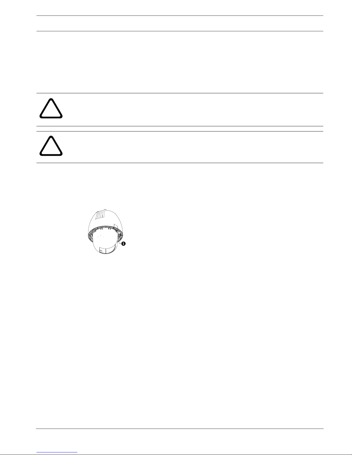
2. Locate the SD card slot (item one in the figure below).
Figure5.1: Camera cross section with SD card slot
3. Orient the card so that the side with the golden contacts faces away from the dome and
towards the housing. The contacts should be at the top as you hold the SD card.
4. Slide the SD card into the slot. Press down the end of the SD cards until you hear a click
and the card locks into place.
5. Follow the steps in one of these sections (depending on the type of camera mount):
Replace the bubble in an in-ceiling housing, page 66 or Replace the bubble in a pendant
housing, page 67.
22 en | Mount Power Supply Box (Wall, Mast (Pole), and Corner Mounts) AUTODOME IP starlight 7000 HD
2016-07 | 1.0 | F.01U.283.679 Operation Manual Bosch Security Systems
6 Mount Power Supply Box (Wall, Mast (Pole), and
Corner Mounts)
Before mounting the Power Supply Box, decide if you should wire the box through the holes in
the bottom or back of the box. If wiring the box through the back, move the two (2) seal plugs
to the bottom through the holes before mounting.
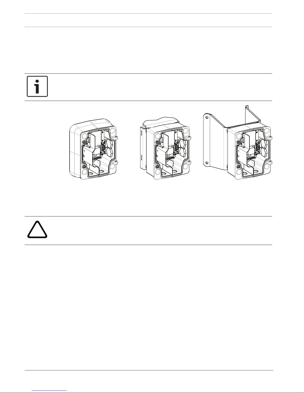
Notice!
Use 3/4-inch (20-mm) NPS fittings for the holes on the bottom and back of the box. Use 1/2inch (15-mm) NPS fittings for the side holes.
Figure6.2: Power Supply Wall, Mast (Pole), and Corner Mounts
1. Use the wall mount template supplied in the packaging box to locate the four (4)
mounting holes for the Power Supply Box.
2. Drill four (4) holes for the mounting anchors. If installing outdoors, apply a weatherproof
sealant around each hole at the mounting surface.
!
Warning!
A stud diameter of 6.4 mm (1/4 inch) to 8 mm (5/16 inch) able to withstand a 120kg (265 lb)
pull-out force is recommended. The mounting material must be able to withstand this pull out
force. For example, 19-mm (3/4-inch) minimum for plywood.
3. Place the Power Supply Box into the optional Trim Skirt.
4. Secure the Power Supply Box to the mounting surface.
For a Wall installation: Use four (4) corrosion-resistant, stainless steel studs (not
supplied). Then proceed to Step 5 below.
For a Corner installation: Secure the Corner Plate to the wall corner using four (4) studs
(not included). Then proceed to Step 5 below.
For a Mast or a pole installation: The metal straps included with the Mast mount
accommodate a pole with a diameter of 100–380 mm (4–15 in.). You must use a banding
tool (sold separately) for a mast or pole installation. Follow the instructions provided
with the banding tool to securely mount the Mast Plate to the pole. Contact your Bosch
Sales Representative to order Banding Tool P/N TC9311PM3T.
5. Secure the Power Supply Box to the Corner Plate or Mast Plate using the four (4) 3/8 x
1-3/4-inch bolts and split lock washers (supplied).
6. Attach 3/4-inch (20-mm) NPS watertight, earth-grounded conduit pipe fittings (not
supplied) to the bottom or back holes of the Power Supply Box through which you will
run the power, video, and control data wires.

AUTODOME IP starlight 7000 HD Mount Power Supply Box (Wall, Mast (Pole), and Corner Mounts) | en 23
Bosch Security Systems Operation Manual 2016-07 | 1.0 | F.01U.283.679
!
Warning!
For units intended to be installed outdoors: All wiring (power and I/O cabling) connecting to
the unit must be routed separately inside different permanently earthed metal conduits (not
supplied).
24 en | Installing the Pendant Arm Wall, Corner, and Mast (Pole) Mounts AUTODOME IP starlight 7000 HD
2016-07 | 1.0 | F.01U.283.679 Operation Manual Bosch Security Systems
7 Installing the Pendant Arm Wall, Corner, and Mast
(Pole) Mounts
7.1 Description
This chapter details how to install an AUTODOME to a Wall, Corner, or Mast (pole) mount. Any
differences to the installation between these two mounting systems are noted.
7.2 Route Wires and Attach Connectors
Notice!
If you plan to route the power through an intermediate power supply box, refer to Route
Power through Intermediate Power Supply Box, page 28.
Power wires must be routed to the left (front) side of the Power Supply Box through a
separate electrically earth-grounded conduit. All video, control, and alarm wires must be
routed through a second electrically earth-grounded conduit to the right side of the box.
!
Warning!
External interconnecting cables are to be installed in accordance to NEC, ANSI/NFPA70 (for
US application) and Canadian Electrical Code, Part I, CSA C22.1 (for CAN application) and in
accordance to local country codes for all other countries.
Branch circuit protection incorporating a 20 A, 2-pole Listed Circuit Breaker or Branch Rated
Fuses are required as part of the building installation. A readily accessible 2-pole disconnect
device with a contact separation of at least 3 mm (0.12 in.) must be incorporated.
Making the Connections
Notice!
Refer to the Connection, page 73 chapter for wire specifications and distances.
1. Route all video, control, and alarm wires through the earth-grounded conduit fitting on
the right side of the power box.
2. Route the high voltage 115/230 VAC lines through the earth-grounded conduit fitting on
the left side of the box. The Power Supply Box with a transformer comes with a barrier
that separates the high voltage side on the left, from the low voltage 24 VAC side on the
right.
3. Cut and trim all wires with sufficient slack to reach their connector terminals in the box,
but not so long as to be pinched by or to obstruct closing the Pendant Arm. Refer to the
image above for the connector locations.
4. Attach the supplied 3-pin Power Plug to the incoming power wires. Refer to connector
P101 for wire connections.
5. If audio input and/or audio output is required, attach the supplied 6-pin SERIAL
COMMUNICATIONS to P106 in the Power Supply Box. Refer to connector P106 in the
Power Supply Box Connections section below.
6. Attach an RJ45 plug to the incoming Ethernet cable.
Connecting Alarm Inputs and Outputs
4 To connect alarm inputs and outputs, attach the supplied 6-pin Alarms In and the 4-pin
Alarms Out connector plugs with flying lead wires to the appropriate incoming alarm
wires. Alarm Out 4 is a relay.
AUTODOME IP starlight 7000 HD Installing the Pendant Arm Wall, Corner, and Mast (Pole) Mounts | en 25
Bosch Security Systems Operation Manual 2016-07 | 1.0 | F.01U.283.679
1
1
2
3
4
5
6
2
3
4
N.O. COM N.C. A1 GND A2
1
PIN
PIN
P102
P103
P104
WHITE
ORANGE
BROWN
GREEN
WHITE
ORANGE
BROWN
GREEN
YELLOW
BLUE
2
3
4
5
6
7
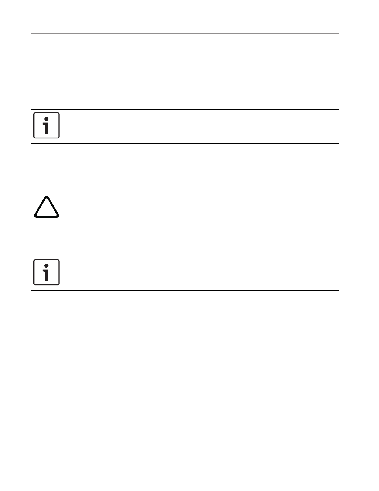
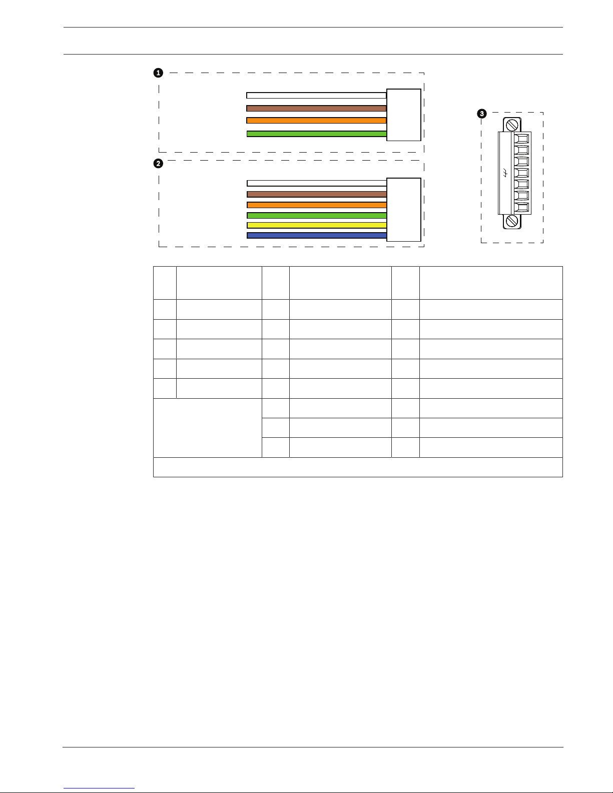
Figure7.3: Alarm and relay connectors
1 4-pin Alarm
Connector (P102)
2 6-pin Alarm In
Connector (P103)
3 7-pin Relay Connector (P104)
Pin Description Pin Description Pin Description
1 Alarm Out 1 1 Alarm in 3 1 Alarm Out 4 Normally Open
2 Alarm Out 2 2 Alarm in 4 2 Alarm Out 4 COM
3 Alarm Out 3 3 Alarm in 5 3 Alarm Out 4 Normally Closed
4 Alarm Ground 4 Alarm in 6 4 Earth Ground
5 Alarm in 7 5 Analog Alarm 1
6 Alarm Ground 6 Analog Alarm 2
7 Ground
For in-ceiling mount only: Low Voltage TTL (3.3V) can also be used.
4 If you are connecting supervised alarms and relays, attach the supplied 7-pin Relay
Connector to the appropriate incoming wires. Refer to Make Connections in the Power
Supply Box, page 32 for additional information.
26 en | Installing the Pendant Arm Wall, Corner, and Mast (Pole) Mounts AUTODOME IP starlight 7000 HD
2016-07 | 1.0 | F.01U.283.679 Operation Manual Bosch Security Systems
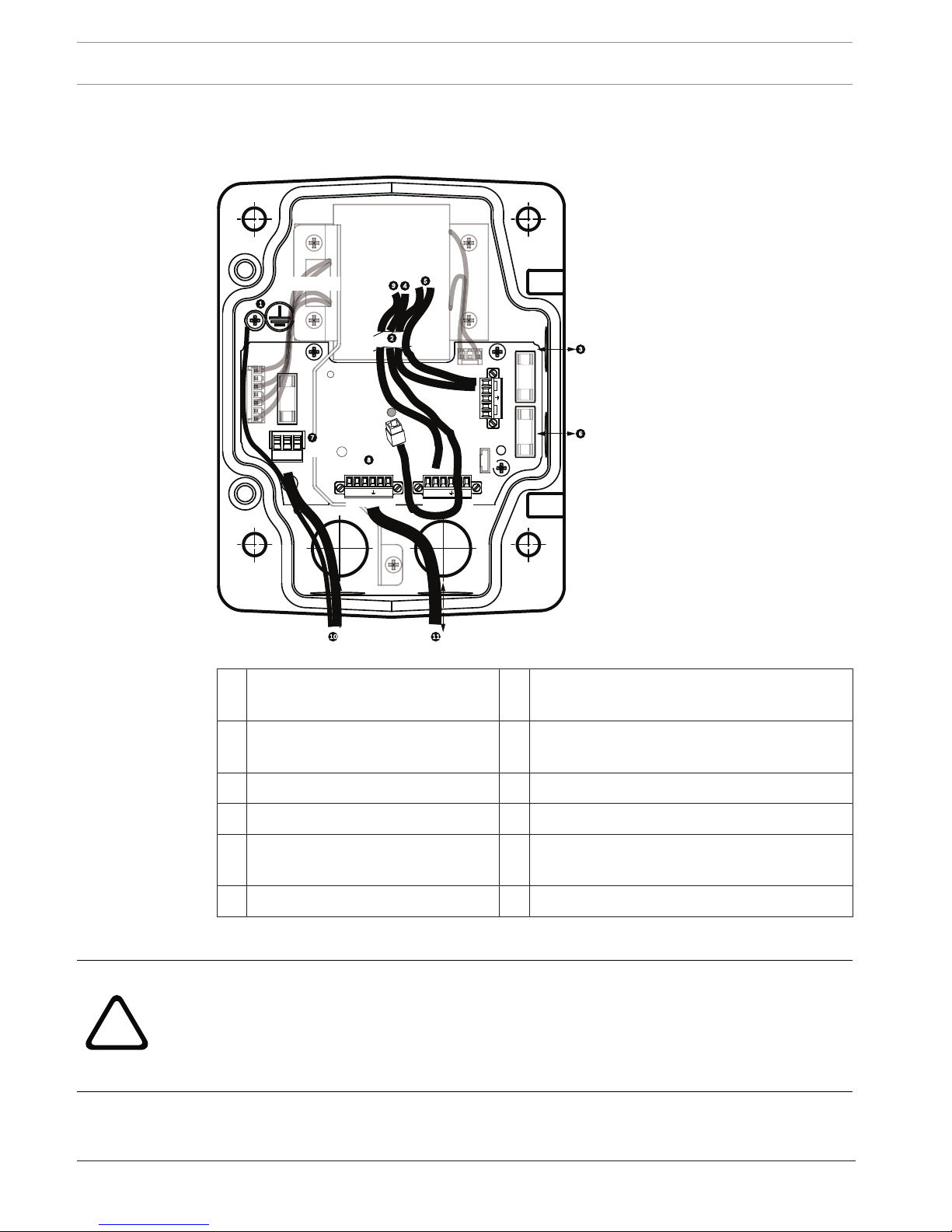
Power Supply Box Connections
The following figure is a detailed illustration of the Pendant Arm Power Supply Box, which
includes the fuse specifications.
TRANSFORMER
(115/230VAC
MODELS)
P101
1 2 3
6 5 4 3 2 1 6 5 4 3 2 1
P106
XF102 XF103
XF101
J102
J101
J101
J101
J101
J101
J101
J101
(LED)
P107
5 4 3 2 1
GND TXD RXD C+ C-
P105
GND TXD RXD C+ C-
HTR DOME
a
LINE NC NEUT
Figure7.4: Pendant arm power supply box
1 Ground Screw 7 P101 Connector; Power In (120 VAC / 220
VAC)
2 From Harness (Nexus cable bundle) 8 P106 Connector; Control In/Out for external
audio input and output
3 In/Out; 1/2 in. (15 mm) NPS Fitting 9 P105 Connector; Audio to camera
4 Ethernet connector 10 Power In; 3/4 in. (20 mm) NPS Fitting
5 P107 Connector; 24 VAC to camera 11 Audio Input/Output; 3/4 in. (20 mm) NPS
Fitting (labeled “SERIAL COMMUNICATIONS”)
6 In/Out; 1/2 in. (15 mm) NPS Fitting
!
Warning!
In earlier Bosch AUTODOME cameras, cable 8 in the ARM mount is labeled “Control In/Out”
and was used for external RxD/TxD and Biphase communications. In the AUTODOME 7000
Series cameras: If you are mounting an AUTODOME 7000 Series camera to an ARM mount
that was wired for an earlier model of Bosch AUTODOME, you must either re-wire cable 8 to
be audio input and output, or disconnected it from the power supply.
Cables/wires that are routed through number 2 in the illustration above come from the Nexus
cable bundle that is in the pendant Arm.
AUTODOME IP starlight 7000 HD Installing the Pendant Arm Wall, Corner, and Mast (Pole) Mounts | en 27
Bosch Security Systems Operation Manual 2016-07 | 1.0 | F.01U.283.679
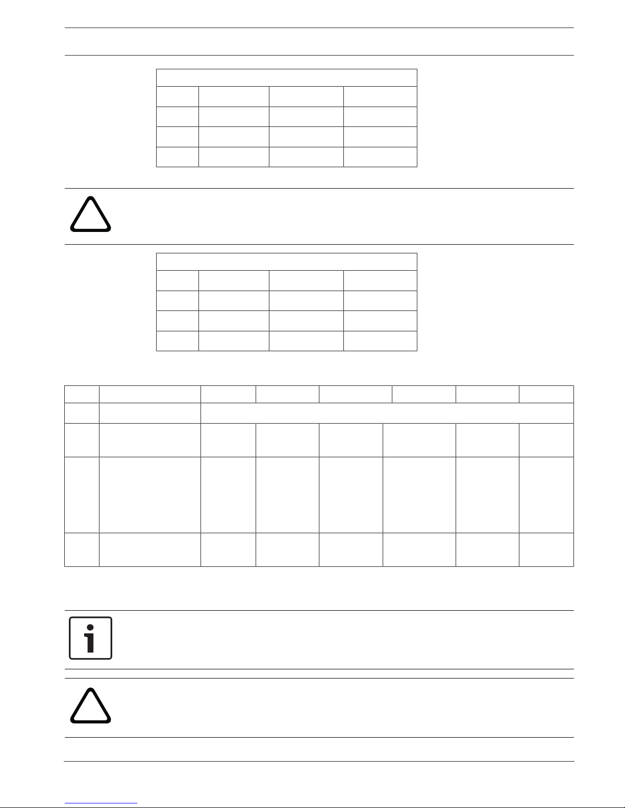
Fuse Specifications
Volts XF101 Mains XF102 Camera XF103 Heater
24 V T 5.0 A T 2.0 A T 3.15 A
115 V T 1.6 A T 2.0 A T 3.15 A
230 V T 0.8A T 2.0 A T 3.15 A
!
Warning!
Fuse replacement by qualified service personnel only. Replace with same type fuse.
Fuse Specifications
Volts XF101 Mains XF102 Camera XF103 Heater
24 V T 5.0 A T 2.0 A T 3.15 A
115 V T 1.6 A T 2.0 A T 3.15 A
230 V T 0.8A T 2.0 A T 3.15 A
The following table lists the Power Supply Box connectors:
No. Connector Pin 1 Pin 2 Pin 3 Pin 4 Pin 5 Pin 6
Ground Grounding Screw
P101 115/230 VAC or
24VAC Power In
Line NC Neutral
P106 SERIAL
COMMUNICATIONS
CODE(Audio IN-,
Audio in
signal
ground)
CODE+
(Audio IN+)
Earth GND
(Ground)
(Audio)
RXD
(Audio OUT+)
TXD
(Audio OUT-;
Audio out
signal
ground)
Signal
GND
(Ground)
P107 24VAC Power
(Arm Harness)
Camera
24VAC
Camera
24VAC
Earth
Ground
Heater
(24VAC)
Heater
(24VAC)
Table7.1: Power Supply Box Connections
Notice!
Pins for P106 1, 2, 4, and 5 are used for audio input and output for AUTODOME 7000 Series
cameras; however, their labels are still those of previous versions of analog AUTODOME
cameras.
!
Warning!
For units intended to be installed outdoors: All wiring (power and I/O cabling) connecting to
the unit must be routed separately inside different permanently earthed metal conduits (not
supplied).
28 en | Installing the Pendant Arm Wall, Corner, and Mast (Pole) Mounts AUTODOME IP starlight 7000 HD
2016-07 | 1.0 | F.01U.283.679 Operation Manual Bosch Security Systems
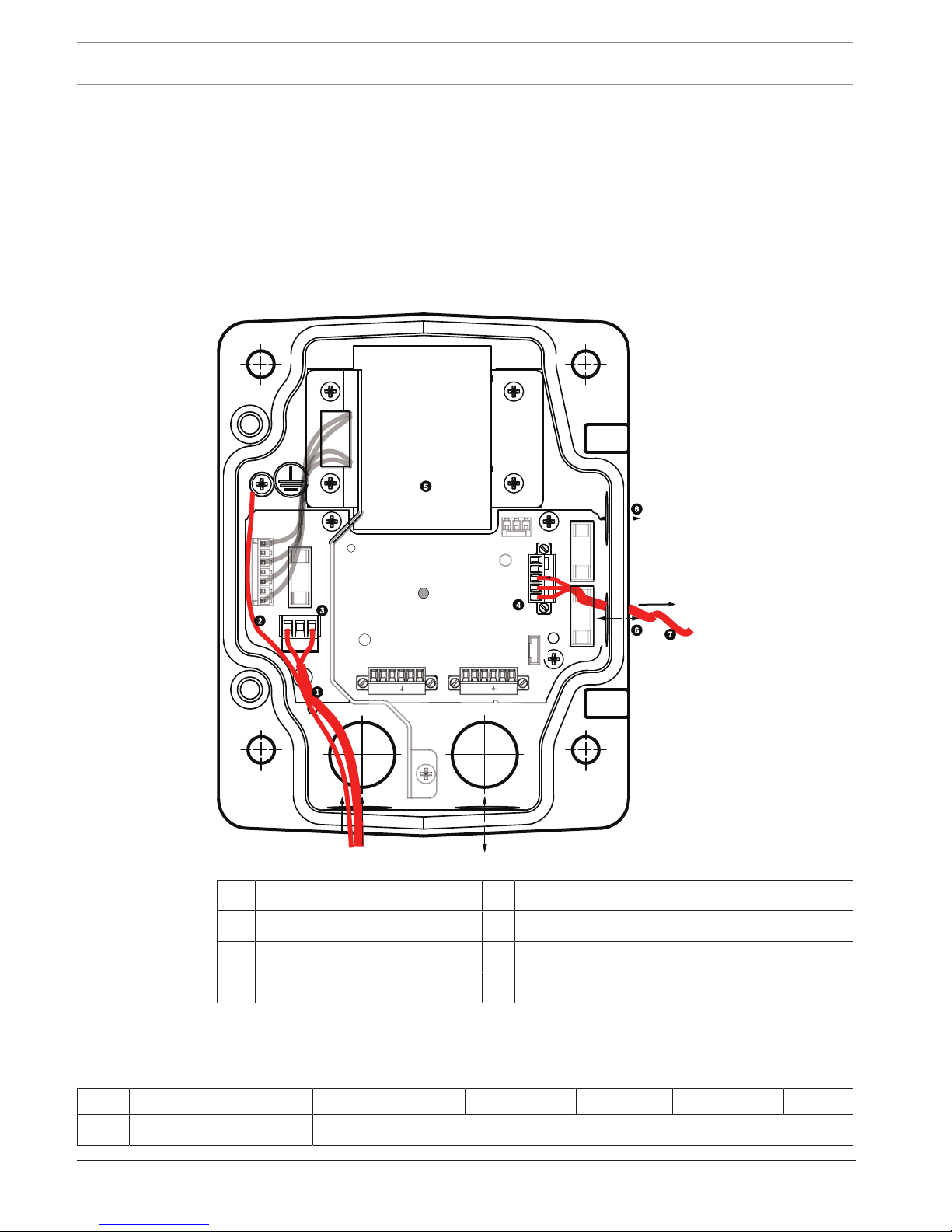
7.3 Route Power through Intermediate Power Supply Box
You may route the main power supply through a VG4-PSU1 (120 V transformer) or through a
VG4-PSU2 (230 V transformer) Power Supply Box before connecting the power to a VG4-PA0
(24 V, no transformer) Power Supply Box. The main issue with this configuration is that the 5pin power out connector from the VG4-PSU1 or VG4-PSU2 does not match to the 3-pin power
input of the VG4-PA0 power supply. The illustration below depicts:
– A VG4-PSU1/VG4-PSU2 Power Supply Box.
– The main power supply connected to the P101 connector and to the grounding screw.
– The 24 VAC power out wire connected to the P107 heater power connectors.
GND
T
XD RXD
C+
C-
GND
T
XD RXD
C+
C-
P101
1 2 3
6 5 4 3 2 1
6 5 4 3 2 1
6 5 4 3 2 1
P106
P105
P107
XF102 XF103
XF101
5 4 3 2 1
J102
J101
(LED)
VG4-PSU1 / VG4-PSU2
HTR DOME
LINE NC NEUT
Figure7.5: VG4-PSU1/VG4-PSU2
1 120/230 VAC Power In 5 Transformer
2 Ground Wire 6 In/Out Conduit (1/2 in. [15 mm] NPS Fitting
3 P101 Connector 7 24 VAC Power Out to VG4-PA0
4 P107 Connector
To properly wire the incoming high voltage and the outgoing low voltage lines, refer to this
table:
No. Connector Pin 1 Pin 2 Pin 3 Pin 4 Pin 5 Pin 6
Ground Grounding Screw
AUTODOME IP starlight 7000 HD Installing the Pendant Arm Wall, Corner, and Mast (Pole) Mounts | en 29
Bosch Security Systems Operation Manual 2016-07 | 1.0 | F.01U.283.679
No. Connector Pin 1 Pin 2 Pin 3 Pin 4 Pin 5 Pin 6
P101 120/230 VAC Power In Line NC Neutral
P107 24VAC Power Out Earth Ground Heater
(24VAC)
Heater
(24VAC)
Table7.2: VG4-PSU1/VG4-PSU2 Power Supply Box Connections
1. Route the high voltage 120/230 VAC lines through the earth-grounded conduit fitting on
the left side of the box. The Power Supply Box with a transformer comes with a barrier
that separates the high voltage side on the left, from the low voltage 24 VAC side on the
right.
2. Cut and trim the high voltage 120/230 VAC power and ground wires with sufficient slack
to reach their connector terminal in the box, but not so long as to be pinched by or to
obstruct closing the cover door.
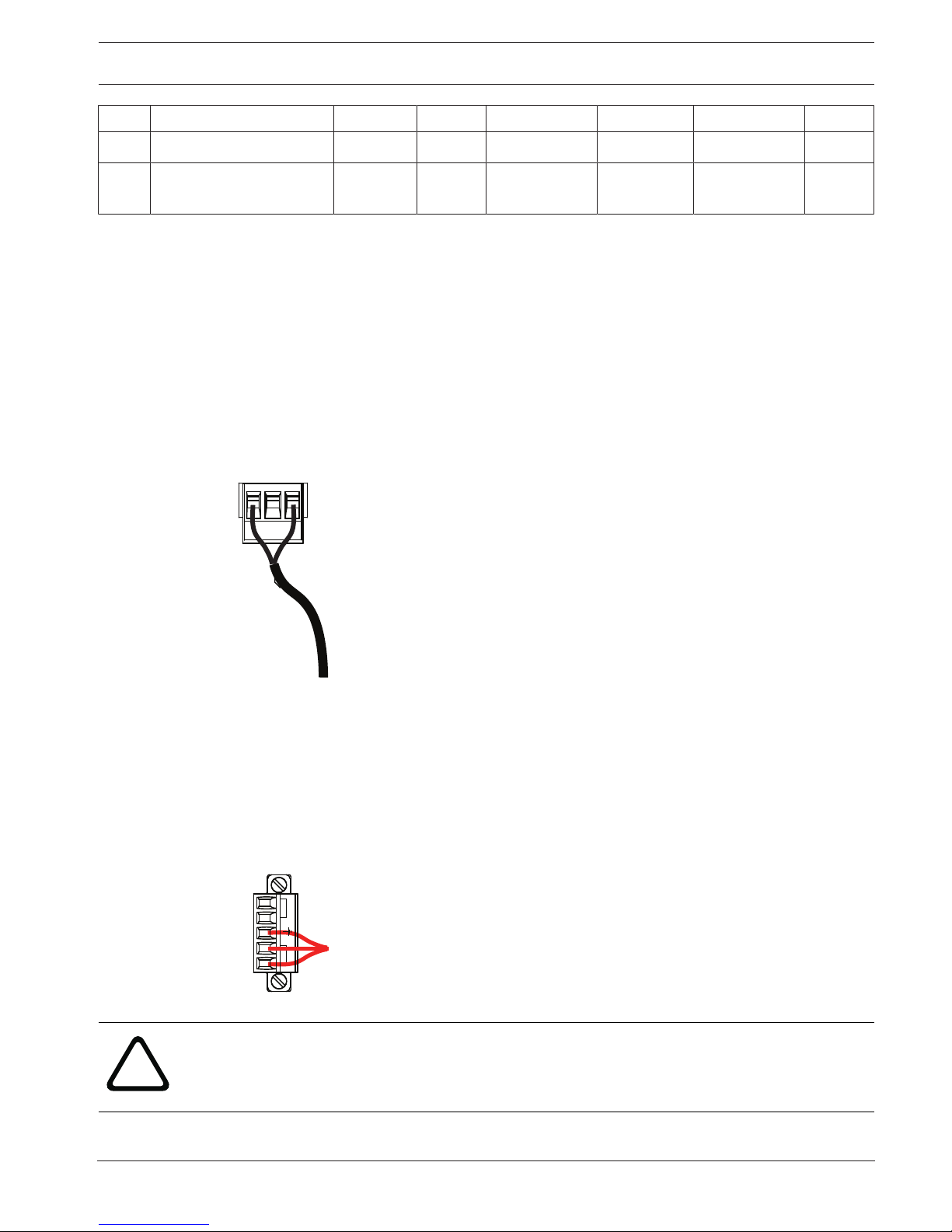
3. Attach the supplied 3-pin power plug to the incoming high voltage power wires in the
box. Refer to connector P101 in the table above and to the image below for an illustration
of these connections:
P101
1 2 3
LINE NC NEUT
Figure7.6: Incoming 115/230 VAC power supply
4. Attach the ground wire to the grounding screw.
5. Connect three wires to the P107 Power Out connector to route the 24 VAC power supply
to the VG4-PA0 Power Supply Box.
Connect the first wire to pin 5 (HN: Heater Neutral) connector.
Connect the second wire to pin 4 (HL: Heater Line) connector.
Connect the third wire to pin 3 (Earth Ground) connector.
Refer to connector P107 in the table above and to the image below for an illustration of
these connections:
P107
5 4 3 2 1
HTR DOME
Figure7.7: Outgoing 24 VAC power supply
!
Warning!
Ensure that you connect the outgoing power supply wires to the P107 heater connectors (HN
and HL). The heater power (XF103) fuse can handle a higher amperage (3.15A) than the
camera power (XF102) fuse (2.0 A).

30 en | Installing the Pendant Arm Wall, Corner, and Mast (Pole) Mounts AUTODOME IP starlight 7000 HD
2016-07 | 1.0 | F.01U.283.679 Operation Manual Bosch Security Systems
6. Route the 24 VAC outgoing power supply wires into the VG4-PA0 power supply box
through the conduit fitting on the left side of the box.
7. Cut and trim the 24 VAC power and ground wires with sufficient slack to reach their
connector terminal in the box, but not so long as to be pinched by or to obstruct closing
the cover door.
8. Attach the supplied 3-pin power plug to the incoming 24 VAC power wires in the box, as
illustrated below.
GND
XD
XD
C+
C-
GND
XD
XD
C+
C-
P101
1 2 3
6 5 4 3 2 1
6 5 4
6 5 4 3 2 1
P106
P105
P107
XF102 XF103
XF101
5 4 3 2 1
J102
J101
(LED)
HTR DOME
24V NC 24V
Figure7.8: VG4-PA0 Power Supply Box
1 Incoming 24 VAC Power Supply Wires (from VG4-PSU1/VG4-PSU2 power supply box)
2 Ground Wire
3 P101 Connector
4 Control Data and Video In/Out Wires (analog models only)
9. Follow the instructions in Attach Pendant Arm to Power Supply Box, page 30 to continue the
installation.
7.4 Attach Pendant Arm to Power Supply Box
The bottom hinge pin of the Pendant Arm is provided with a Hinge Pin Stop to hold the hinge
open while attaching the arm to the Power Supply Box.
1. Compress the bottom hinge pin by pushing the pin lever downward and rotating it behind
the Hinge Pin Stop.
 Loading...