

Page 1
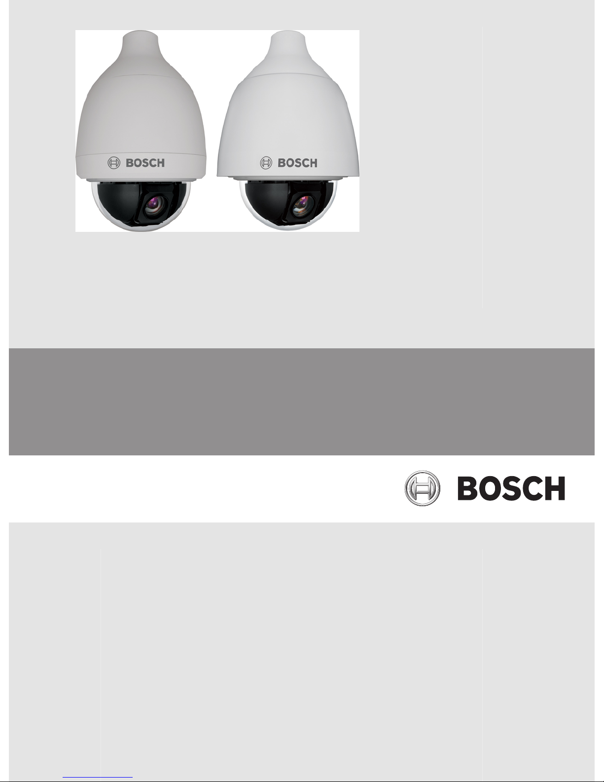
AUTODOME 5000 Analog PTZ Camera
VEZ-5000
en Operations Manual
Page 2

Page 3

Table of contents
1
Safety 5
1.1 About this Manual 5
1.2 Conventions in this Manual 5
1.3 Legal Information 5
1.4 Important Safety Instructions 5
1.5 Important Notices 7
1.6 FCC and ICES Compliance (Class A) 9
2
Description 11
3
Unpacking 12
3.1 Parts List 12
4
Installation 14
5
Connection 15
5.1 Switches/Connectors 15
5.2 Communication Switch Setting 16
5.3 ID Setting 16
5.4 Camera Control Protocol Setting 17
5.5 Power Connector 18
5.6 Alarm I/O 18
5.7 RS-485 Connector Definition 19
5.8 Prepare the Camera for Assembly 20
5.9 Assemble the Indoor Camera 20
5.10 Assemble the Outdoor Camera 21
5.11 Accessories 22
6
On-Screen Display (OSD) Menu 24
6.1 Camera Setup Menu 24
6.2 Lens Setup Menu 26
6.3 PTZ Setup Menu 27
6.4 Display Setup Menu 29
6.5 Alarm Setup Menu 30
6.6 Language Setup Menu 31
6.7 Installer Menu 32
6.8 Monitor Display 33
6.9 Main Menu 35
6.9.1 Common Menus 36
6.10 Camera Setup 37
6.10.1 White Balance 37
6.10.2 Video Level 38
6.10.3 AutoSensUp Max 38
6.10.4 Exposure Mode 38
6.10.5 Backlight 39
6.10.6 Sharpness 39
6.10.7 WDR Function 39
6.10.8 Night Mode 39
6.10.9 Enhancement 39
6.10.10 DNR 39
6.11 Lens Setup 40
6.11.1 Auto Focus 40
AUTODOME 5000 Analog PTZ Camera Table of Contents | en 3
Bosch Security Systems, Inc. Operations Manual 2013.07 | 1.3 |
Page 4

6.11.2 Digital Zoom 40
6.12 PTZ Setup 40
6.12.1 Autopan 41
6.12.2 Tour 42
6.12.3 Preset Tour 43
6.12.4 Preset 44
6.12.5 Freeze 46
6.12.6 Home Setting 46
6.12.7 Schedule 47
6.12.8 Misc. Function 48
6.13 Display Setup 48
6.13.1 ID Display 49
6.13.2 Title Display 49
6.13.3 Privacy Masking 50
6.13.4 Time Setting 51
6.13.5 Motion Track 52
6.14 Alarm Setup 52
6.14.1 Alarm Setting 52
6.14.2 Alarm Detect 55
6.15 Language 57
6.16 Installer Setup 57
6.16.1 System Setup 57
6.16.2 Camera Setting 60
7
Operation 62
8
Troubleshooting 66
9
Technical data 68
10
Appendices 69
4 en | Table of Contents AUTODOME 5000 Analog PTZ Camera
2013.07 | 1.3 | Operations Manual Bosch Security Systems, Inc.
Page 5
Safety
About this Manual
This manual has been compiled with great care and the information it contains has been
thoroughly verified. The text was complete and correct at the time of printing. Because of the
ongoing development of products, the content of the manual may change without notice.
Bosch Security Systems accepts no liability for damage resulting directly or indirectly from
faults, incompleteness, or discrepancies between the manual and the product described.
Conventions in this Manual
In this manual, the following symbols and notations are used to draw attention to special
situations:
Danger!
This symbol indicates an imminently hazardous situation such as “Dangerous Voltage” inside
the product. If not avoided, this will result in an electrical shock, serious bodily injury, or
death.
!
Warning!
Indicates a potentially hazardous situation. If not avoided, this could result in serious bodily
injury or death.
!
Caution!
Medium Risk
Indicates a potentially hazardous situation. If not avoided, this may result in minor or
moderate injury. Alerts the user to important instructions accompanying the unit.
!
Caution!
Indicates a potentially hazardous situation. If not avoided, this may result in property damage
or risk of damage to the unit.
Notice!
This symbol indicates information or a company policy that relates directly or indirectly to the
safety of personnel or protection of property.
Legal Information
Copyright
This manual is the intellectual property of Bosch Security Systems, Inc. and is protected by
copyright. All rights reserved.
Trademarks
All hardware and software product names used in this document are likely to be registered
trademarks and must be treated accordingly.
Important Safety Instructions
Read, follow, and retain for future reference all of the following safety instructions. Heed all
warnings on the unit and in the operating instructions before operating the unit.
1
1.1
1.2
1.3
1.4
AUTODOME 5000 Analog PTZ Camera Safety | en 5
Bosch Security Systems, Inc. Operations Manual 2013.07 | 1.3 |
Page 6

1. Cleaning - Unplug the unit from the outlet before cleaning. Follow any instructions
provided with the unit. Generally, using a dry cloth for cleaning is sufficient, but a moist
fluff-free cloth or leather shammy may also be used. Do not use liquid cleaners or aerosol
cleaners.
2. Heat Sources - Do not install the unit near any heat sources such as radiators, heaters,
stoves, or other equipment (including amplifiers) that produce heat.
3. Ventilation - Any openings in the unit enclosure are provided for ventilation to prevent
overheating and ensure reliable operation. Do not block or cover these openings. Do not
place the unit in an enclosure unless proper ventilation is provided, or the manufacturer's
instructions have been adhered to.
4. Object and liquid entry - Never push objects of any kind into this unit through openings
as they may touch dangerous voltage points or short-out parts that could result in a fire
or electrical shock. Never spill liquid of any kind on the unit. Do not place objects filled
with liquids, such as vases or cups, on the unit.
5. Lightning - For added protection during a lightning storm, or when leaving this unit
unattended and unused for long periods, unplug the unit from the wall outlet and
disconnect the cable system. This will prevent damage to the unit from lightning and
power line surges.
6. Controls adjustment - Adjust only those controls specified in the operating instructions.
Improper adjustment of other controls may cause damage to the unit. Use of controls or
adjustments, or performance of procedures other than those specified, may result in
hazardous radiation exposure.
7. Overloading - Do not overload outlets and extension cords. This can cause fire or
electrical shock.
8. Power cord and plug protection - Protect the plug and power cord from foot traffic,
being pinched by items placed upon or against them at electrical outlets, and its exit from
the unit. For units intended to operate with 230 VAC, 50 Hz, the input and output power
cord must comply with the latest versions of IEC Publication 227 or IEC Publication 245.
9. Power disconnect - Units have power supplied to the unit whenever the power cord is
inserted into the power source, or when High Power-over-Ethernet (High PoE) power is
provided over the Ethernet CAT 5E/6 cable. The unit is operational only when the ON/OFF
switch is in the ON position. The power cord is the main power disconnect device for
switching off the voltage for all units. When High PoE or PoE+ (820.3at) is used to power
the unit, the power is provided over the Ethernet cable, which is then the main power
disconnect device for switching off the voltage for all units.
10. Power sources - Operate the unit only from the type of power source indicated on the
label. Before proceeding, be sure to disconnect the power from the cable to be installed
into the unit.
For battery powered units, refer to the operating instructions.
For external power supplied units, use only the recommended or approved power
supplies.
For limited power source units, this power source must comply with EN60950.
Substitutions may damage the unit or cause fire or shock.
For 24 VAC units, voltage applied to the unit's power input should not exceed ±10%, or
28 VAC. User-supplied wiring must comply with local electrical codes (Class 2 power
levels). Do not ground the supply at the terminals or at the unit's power supply terminals.
If unsure of the type of power supply to use, contact your dealer or local power company.
11. Servicing - Do not attempt to service this unit yourself. Opening or removing covers may
expose you to dangerous voltage or other hazards. Refer all servicing to qualified service
personnel.
6
en | Safety AUTODOME 5000 Analog PTZ Camera
2013.07 | 1.3 | Operations Manual Bosch Security Systems, Inc.
Page 7

12. Damage requiring service - Unplug the unit from the main AC power source and refer
servicing to qualified service personnel when any damage to the equipment has occurred,
such as:
the power supply cord or plug is damaged;
exposure to moisture, water, and/or inclement weather (rain, snow, etc.);
liquid has been spilled in or on the equipment;
an object has fallen into the unit;
unit has been dropped or the unit cabinet is damaged;
unit exhibits a distinct change in performance;
unit does not operate normally when the user correctly follows the operating instructions.
13. Replacement parts - Be sure the service technician uses replacement parts specified by
the manufacturer, or that have the same characteristics as the original parts.
Unauthorized substitutions may cause fire, electrical shock, or other hazards.
14. Safety check - Safety checks should be performed upon completion of service or repairs
to the unit to ensure proper operating condition.
15. Installation - Install in accordance with the manufacturer's instructions and in accordance
with applicable local codes.
16. Attachments, changes or modifications - Only use attachments/accessories specified by
the manufacturer. Any change or modification of the equipment, not expressly approved
by Bosch, could void the warranty or, in the case of an authorization agreement, authority
to operate the equipment.
Important Notices
Accessories - Do not place this unit on an unstable stand, tripod, bracket, or mount. The unit
may fall, causing serious injury and/or serious damage to the unit. When a cart is used, use
caution and care when moving the cart/apparatus combination to avoid injury from tip-over.
Quick stops, excessive force, or uneven surfaces may cause the cart/unit combination to
overturn. Mount the unit per the manufacturer's instructions.
All-pole power switch - Incorporate an all-pole power switch, with a contact separation of at
least 3 mm in each pole, into the electrical installation of the building. If you must open the
housing for servicing and/or other activities, use this all-pole switch as the main disconnect
device for switching off the voltage to the unit.
Camera grounding - For mounting the camera in potentially damp environments, ensure to
ground the system using the ground connection of the power supply connector.
Camera lens - An assembled camera lens in the outdoor housing must comply and be tested in
accordance with UL/IEC60950. Any output or signal lines from the camera must be SELV or
Limited Power Source. For safety reasons, the environmental specification of the camera lens
assembly must be within the environmental specification.
Camera signal - Protect the cable with a primary protector if the camera signal is beyond 140
feet, in accordance with NEC800 (CEC Section 60).
Coax grounding:
1.5
AUTODOME 5000 Analog PTZ Camera Safety | en 7
Bosch Security Systems, Inc. Operations Manual 2013.07 | 1.3 |
Page 8
– Ground the cable system if connecting an outside cable system to the unit.
– Connect outdoor equipment to the unit's inputs only after this unit has had its grounding
plug connected to a grounded outlet or its ground terminal is properly connected to a
ground source.
– Disconnect the unit's input connectors from outdoor equipment before disconnecting the
grounding plug or grounding terminal.
– Follow proper safety precautions such as grounding for any outdoor device connected to
this unit.
U.S.A. models only - Section 810 of the National Electrical Code, ANSI/NFPA No.70, provides
information regarding proper grounding of the mount and supporting structure, grounding of
the coax to a discharge unit, size of grounding conductors, location of discharge unit,
connection to grounding electrodes, and requirements for the grounding electrode.
Notice!
This device is intended for use in public areas only.
U.S. federal law strictly prohibits surreptitious recording of oral communications.
Cold Start-ups - If camera is powered up in extremely cold temperature (for example, -40°C),
please allow 30 minutes warm-up after powering camera prior to operation. In some cases,
camera may require a soft reset or a power cycle before usable video is available.
Environmental statement - Bosch has a strong commitment towards the environment. This
unit has been designed to respect the environment as much as possible.
Electrostatic-sensitive device - Use proper CMOS/MOS-FET handling precautions to avoid
electrostatic discharge. NOTE: Wear required grounded wrist straps and observe proper ESD
safety precautions when handling the electrostatic-sensitive printed circuit boards.
Fuse rating - For security protection of the device, the branch circuit protection must be
secured with a maximum fuse rating in accordance with NEC800 (CEC Section 60).
Grounding and polarization - This unit may be equipped with a polarized alternating current
line plug (a plug with one blade wider than the other blade). This safety feature allows the
plug to fit into the power outlet in only one way. If unable to insert the plug fully into the
outlet, contact a locally certified electrician to replace the obsolete outlet. Do not defeat the
safety purpose of the polarized plug.
Alternately, this unit may be equipped with a 3-pole grounding plug (a plug with a third pin for
earth grounding). This safety feature allows the plug to fit into a grounded power outlet only.
If unable to insert the plug into the outlet, contact a locally certified electrician to replace the
obsolete outlet. Do not defeat the safety purpose of the grounding plug.
Moving - Disconnect the power before moving the unit. Move the unit with care. Excessive
force or shock may damage the unit.
Outdoor signals - The installation for outdoor signals, especially regarding clearance from
power and lightning conductors and transient protection, must be in accordance with NEC725
and NEC800 (CEC Rule 16-224 and CEC Section 60).
Permanently connected equipment - Incorporate a readily-accessible disconnect device in the
building installation wiring.
Power lines - Do not locate the camera near overhead power lines, power circuits, or
electrical lights, nor where it may contact such power lines, circuits, or lights.
Video loss - Video loss is inherent to digital video recording; therefore, Bosch Security
Systems cannot be held liable for any damage that results from missing video information. To
minimize the risk of lost digital information, Bosch Security Systems recommends multiple,
redundant recording systems, and a procedure to back up all analog and digital information.
8 en | Safety AUTODOME 5000 Analog PTZ Camera
2013.07 | 1.3 | Operations Manual Bosch Security Systems, Inc.
Page 9
FCC and ICES Compliance (Class A)
FCC ET ICES INFORMATION (commercial applications)
(U.S.A. and Canadian Models Only, CLASS A)
Notice!
This is a class A product. In a domestic environment this product may cause radio
interference, in which case the user may be required to take adequate measures.
This device complies with part 15 of the FCC Rules. Operation is subject to the following
conditions:
– this device may not cause harmful interference, and
– this device must accept any interference received, including interference that may cause
undesired operation.
This equipment has been tested and found to comply with the limits for a Class A digital
device, pursuant to Part 15 of the FCC Rules and ICES-003 of Industry Canada. These limits
are designed to provide reasonable protection against harmful interference when the
equipment is operated in a commercial environment. This equipment generates, uses, and
radiates radio frequency energy and, if not installed and used in accordance with the
instruction manual, may cause harmful interference to radio communications. Operation of
this equipment in a residential area is likely to cause harmful interference, in which case the
user will be required to correct the interference at his expense.
Intentional or unintentional modifications, not expressly approved by the party responsible for
compliance, shall not be made. Any such modifications could void the user's authority to
operate the equipment. If necessary, the user should consult the dealer or an experienced
radio/television technician for corrective action.
The user may find the following booklet, prepared by the Federal Communications
Commission, helpful: How to Identify and Resolve Radio-TV Interference Problems. This
booklet is available from the U.S. Government Printing Office, Washington, DC 20402, Stock
No. 004-000-00345-4.
INFORMATIONS FCC ET ICES (applications commerciales )
(modèles utilisés aux États-Unis et au Canada uniquement, CLASSE A)
Notice!
Ce produit est un appareil de Classe A. Son utilisation dans une zone résidentielle risque de
provoquer des interférences. Le cas échéant, l’utilisateur devra prendre les mesures
nécessaires pour y remédier.
Ce produit est conforme aux normes FCC partie 15. la mise en service est soumises aux deux
conditions suivantes:
– cet appareil ne peut pas provoquer d'interférence nuisible et
– cet appareil doit pouvoir tolérer toutes les interférences auxquelles il est soumit, y
compris les interférences qui pourraient influer sur son bon fonctionnement.
Suite à différents tests, cet appareil s’est révélé conforme aux exigences imposées aux
appareils numériques de Classe A en vertu de la section 15 du règlement de la Commission
fédérale des communications des États-Unis (FCC). Ces contraintes sont destinées à fournir
une protection raisonnable contre les interférences nuisibles quand l'appareil est utilisé dans
une installation commerciale. Cette appareil génère, utilise et émet de l'energie de fréquence
radio, et peut, en cas d'installation ou d'utilisation non conforme aux instructions, générer des
1.6
AUTODOME 5000 Analog PTZ Camera Safety | en 9
Bosch Security Systems, Inc. Operations Manual 2013.07 | 1.3 |
Page 10

interférences nuisibles aux communications radio. L’utilisation de ce produit dans une zone
résidentielle peut provoquer des interférences nuisibles. Le cas échéant, l’utilisateur devra
remédier à ces interférences à ses propres frais.
Au besoin, l’utilisateur consultera son revendeur ou un technicien qualifié en radio/télévision,
qui procédera à une opération corrective. La brochure suivante, publiée par la Commission
fédérale des communications (FCC), peut s’avérer utile : « How to Identify and Resolve RadioTV Interference Problems » (Comment identifier et résoudre les problèmes d’interférences de
radio et de télévision). Cette brochure est disponible auprès du U.S. Government Printing
Office, Washington, DC 20402, États-Unis, sous la référence n° 004-000-00345-4.
10 en | Safety AUTODOME 5000 Analog PTZ Camera
2013.07 | 1.3 | Operations Manual Bosch Security Systems, Inc.
Page 11

Description
The AUTODOME 5000 Analog PTZ Dome Camera delivers up to 432x zoom ratio to capture
clear image in the distance. Continuous Auto Focus, Back Light, Auto Exposure and Auto
SensUp Max functions are provided for clear and high quality image. Night Mode ensures 24
hours operation, while Privacy Masking is specially designed to avoid any intrusive monitoring
at specific region; all of the salient functions can be incorporated to meet your needs. The
Home function allows users to specify a preset position as the “home position” or choose a
preferred action as the “Home function” (Preset Tour / Auto Pan / Tour). If the Home function
is enabled, the camera can return to the preset home position or function when the camera
has been idled for a user-defined period of time. Additionally, the unique Schedule function
enables users to program a preset point or function (Preset Tour / Auto Pan / Tour) for the
selected actions to be automatically initiated at specified times.
The camera provides variable pan/tilt speeds ranging from a fast patrol of 360° per second to
a slow ramble of 5° per second with 0.225° pan/tilt accuracy for fast and accurate tracking
ability. The 360° endless rotation and 0° to 90° tilt travel help to track the object passing
directly beneath the camera. Maximum 99 preset points can be programmed for precise
location of target areas, and users can also define Preset Tour, Auto Pan and Tour lines for the
camera to operate automatically. In addition, a RS-485 communication port is available for
remote control.
The camera provides 4 alarm inputs and 2 alarm relay outputs, and the smart alarm
management mechanism can be programmed through the OSD setup menu. A chosen action
(Preset / Preset Tour / Auto Pan / Tour) can be activated when an alarm is triggered.
The built-in protocols include OSRD and Pelco P/D, which allow the camera to be integrated
with surveillance systems of other suppliers.
Features
– 432X Zoom ( 36X Zoom, 12X Digital)
– 960H Double Scan CCD sensor
– 720TVL Sensor resolution
– Wide Dynamic Range ( WDR)
– True Day & Night ( IR Cut Filter)
– Digital Noise Reduction
– 360° Endless Pan Range
– 0° to 90° Tilt Angle
– Manual speed 0.5° to 90° /s
– 99 Preset Positions / 5° to 360° per second Pre-position Speed
– 8 Tour
– 4 Autopan
– 8 Preset Tour
– Up to 20 Privacy Masking zone
– Image Enhancement / AGC Control
– 4 Alarm Inputs, 2 Alarm Outputs ( N.C. / N.O./ OFF)
– Multi-language On-Screen Display
– Bosch OSRD, Pelco P/D Protocol
– Compatible external devices ( LTC-5136,MIC-BP3, UPA-2450-50 / UPA-2450-60)
– Programmable PTZ Speed: Proportional to Zoom ratio, changeable preset speed
2
AUTODOME 5000 Analog PTZ Camera Description | en 11
Bosch Security Systems, Inc. Operations Manual 2013.07 | 1.3 |
Page 12
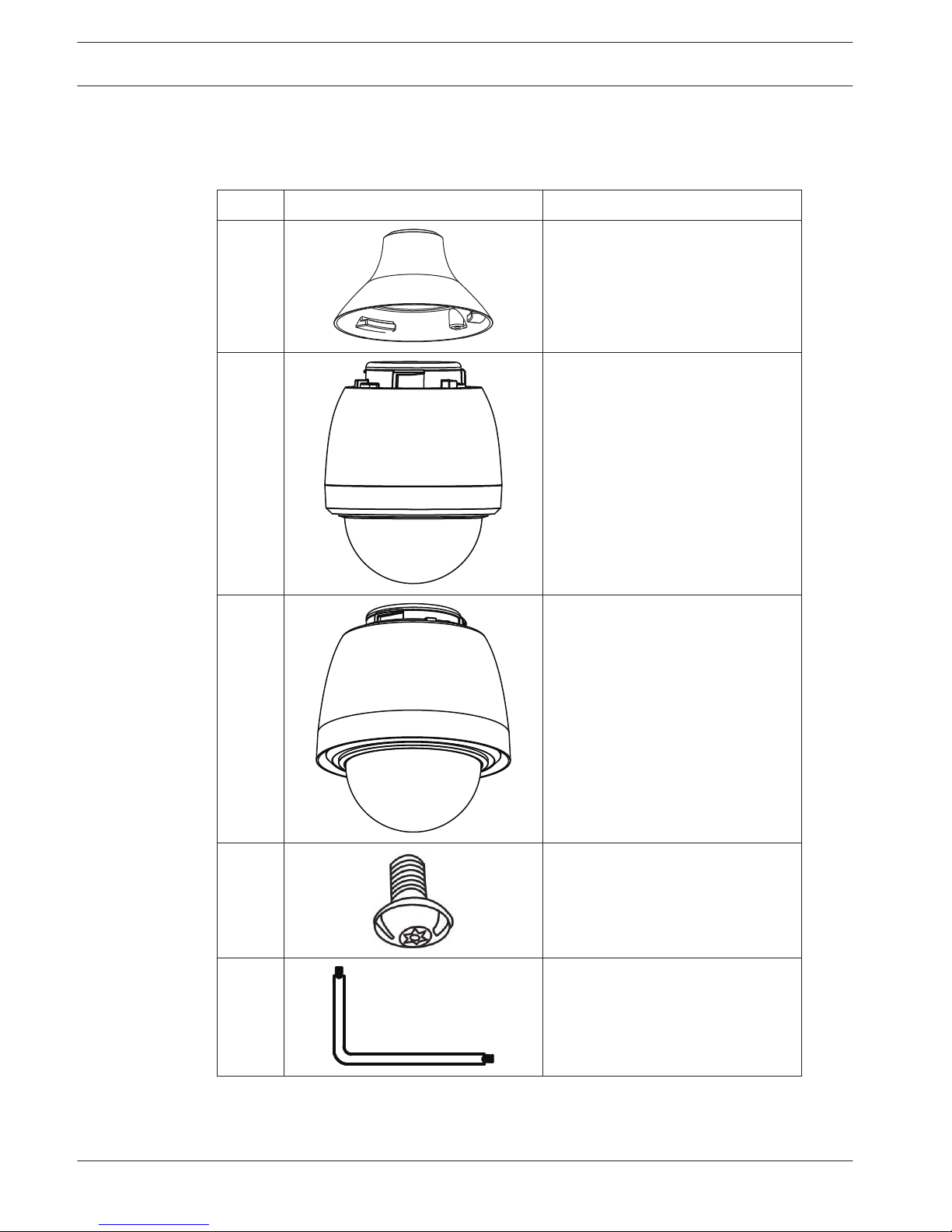
Unpacking
Parts List
Quanity Graphic Description
1 Mounting Adapter
1 Dome Camera Body without
Sunshield
1
1 Dome Camera Body with Sunshield
1
1 M5x8L security screw for mounting
adapter
1 T20 Security Torx wrench for M5x8L
security screw
3
3.1
12 en | Unpacking AUTODOME 5000 Analog PTZ Camera
2013.07 | 1.3 | Operations Manual Bosch Security Systems, Inc.
Page 13
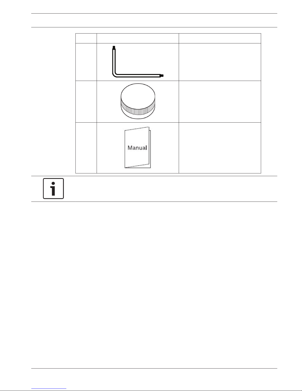
Quanity Graphic Description
1 T10 Security Torx wrench for dome
bubble
1 Lubricant
1 User Manual
Notice!
1. Your package contains one Dome Camera Body, depending if you purchased an indoor
(without sunshield) or an outdoor (with sunshield) camera.
AUTODOME 5000 Analog PTZ Camera Unpacking | en 13
Bosch Security Systems, Inc. Operations Manual 2013.07 | 1.3 |
Page 14

Installation
Follow the instructions below to complete cable connections of the AUTODOME 5000 camera.
Connect the camera to other devices as shown in the diagram to complete a video surveillance
solution.
Figure 4.1: System Configuration
1
Repeater
2 AUTODOME 5000 camera
3 Video cable
4 Switch/Quad/Mux/DVR
5 Main monitor
6 Call monitor
7 Control keyboard
Notice!
To extend the network distance up to 1.2 km (4000 feet) and to protect the connected
devices, it is highly recommended to place a repeater at the mid-point. However, a repeater
may be needed in the network distance less than 1.2 km if the used cables are not the CAT 5,
24-gauge cables. Refer to section RS-485. For detailed information about the repeater, refer
to its manual.
4
14 en | Installation AUTODOME 5000 Analog PTZ Camera
2013.07 | 1.3 | Operations Manual Bosch Security Systems, Inc.
Page 15
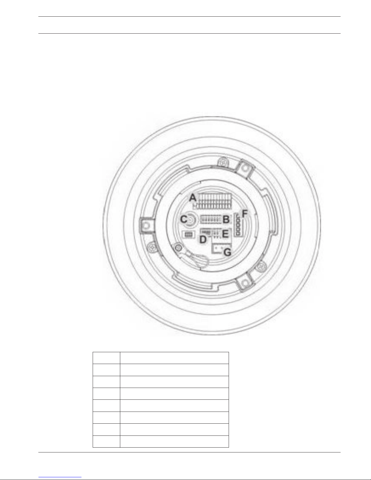
Connection
Switches/Connectors
Configuring the camera’s ID and communication protocol is required before connecting the
camera to other devices. The switches used for configuring these settings are located on the
camera’s back plate.
Refer to the diagram and table below for positions and definition of the switches / connectors.
Letter Description
A Alarm I/O
B Camera ID setup dip switch
C BNC video output
D Communication switch
E Camera control protocol switcher
F RS-485 connector
G Power connector
5
5.1
AUTODOME 5000 Analog PTZ Camera Connection | en 15
Bosch Security Systems, Inc. Operations Manual 2013.07 | 1.3 |
Page 16
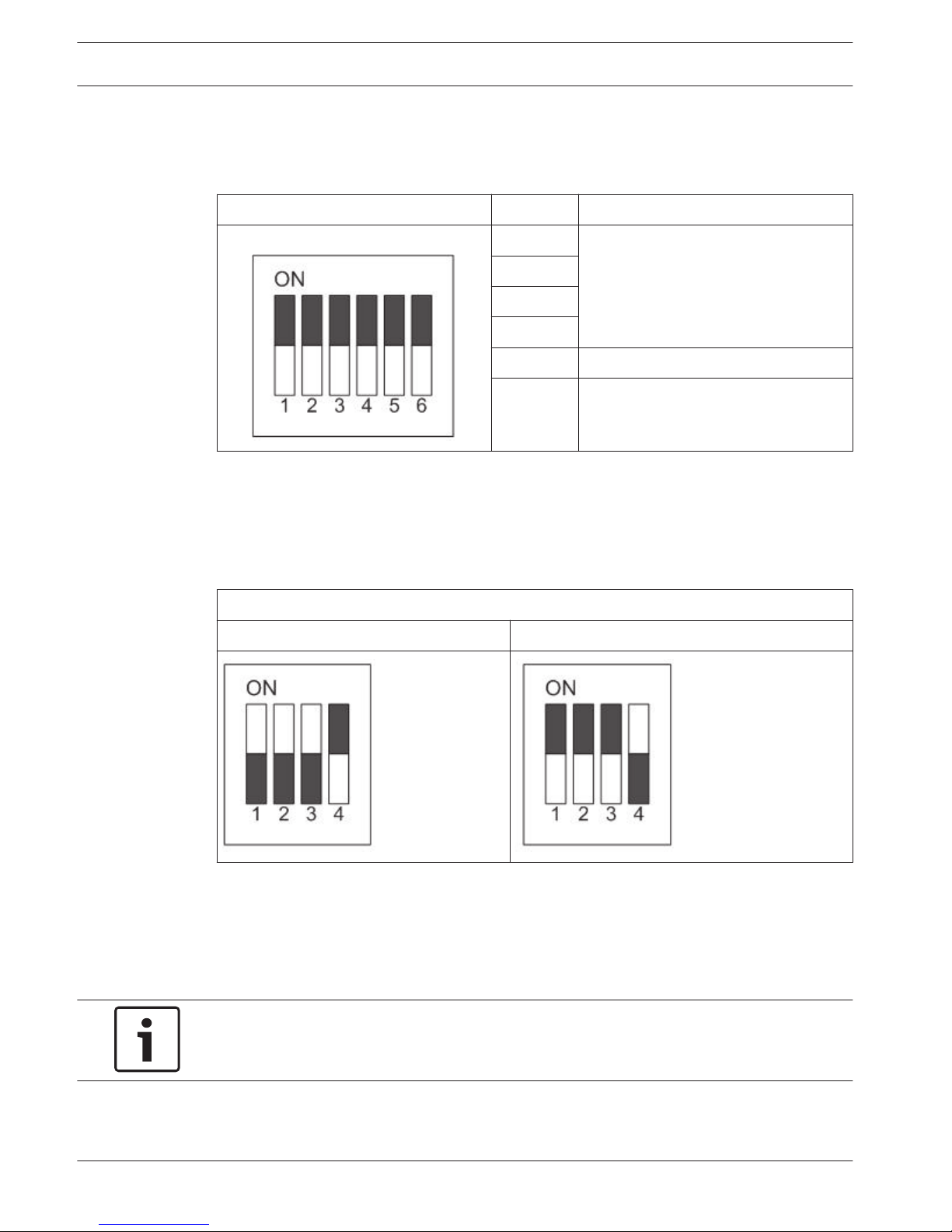
Communication Switch Setting
Communication Switch
The camera’s communication switches are specified in the table below.
Communication Switch Switches Description
SW1
RS-485 Setting
SW2
SW3
SW4
SW5 Reserved
SW6 Reserved
RS-485 Setting
The camera uses an RS-485 interface to communicate with the control device. For this reason,
the RS-485 setup of the camera and the control device must be the same. The default RS-485
setting is half-duplex. Do not change the default setting without any support from qualified
specialists or suppliers.
RS-485 Setting
Half-Duplex Full-Duplex
ID Setting
If there is more than one camera in the same network, you must assign an ID number to each
camera. Access the OSD menu and go to <INSTALLER MENU> → <CAMERA ID SETTING> → <ID
SETTING> to assign the camera’s ID number. Refer to the section Camera Setting for detail
setting instructions.
Notice!
No two cameras in the same network should be given the same ID, or communication conflict
may occur.
5.2
5.3
16 en | Connection AUTODOME 5000 Analog PTZ Camera
2013.07 | 1.3 | Operations Manual Bosch Security Systems, Inc.
Page 17
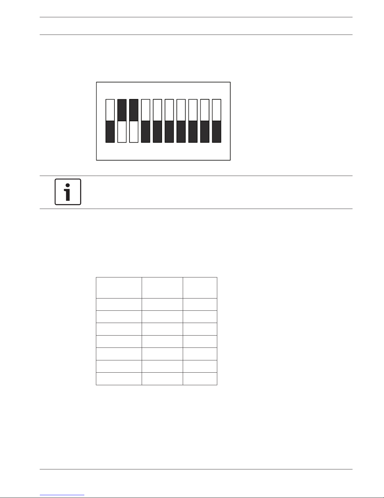
For users who wish to set up the camera ID via the dip switch at the camera’s back plate, first
choose <HW> as the setting type under the <ID SETTING> menu. Then the camera’s ID can be
setup using the 10-bit ID dip switch. If the camera’s ID number is 6, for instance, the ID switch
SW 2 and SW 3 should be set to “ON” and the rest should be set to “OFF” as shown below.
ON
1 2 3 4 5 6 7 8 9 10
For switch configuration details, refer to Appendices, page 69.
Notice!
If you need to setup the camera ID via the dip switch at the camera’s back plate, the setting
type MUST be changed to <HW>. Otherwise the dip switch WILL NOT be enabled.
Camera Control Protocol Setting
Define the camera control protocol according to the devices of the surveillance system.
Generally, use one protocol even the devices are provided from different manufacturers. Refer
to the table below for all supported protocols with their matching switch numbers and baud
rate. Choose an appropriate protocol for the camera.
Switch
Number
Protocol Baud Rate
00 Pelco D 2400
01 Pelco D 4800
02 Pelco D 9600
04 Pelco P 1200
05 Pelco P 4800
06 Pelco D 9600
10 Bosch OSRD 9600
5.4
AUTODOME 5000 Analog PTZ Camera Connection | en 17
Bosch Security Systems, Inc. Operations Manual 2013.07 | 1.3 |
Page 18
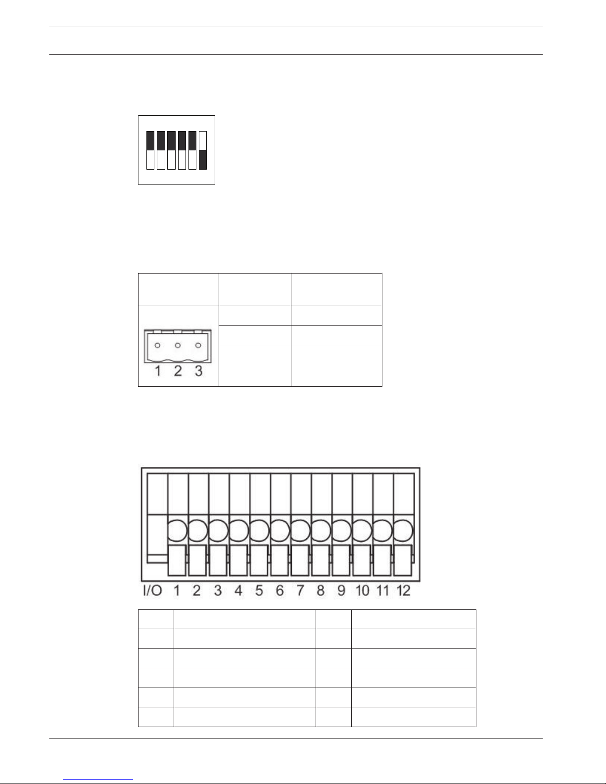
Use the 6-bit dip switch (Camera Control Protocol Switch) to set the camera’s control
protocol and its baud rate. If protocol “Pelco D” is selected, which is switch no. 01 and baud
rate 4800, for instance, set the SW-1 to “ON” and the rest to “OFF” as shown below.
ON
1 2 3 4 5 6
123456
For more switch configurations, refer to Appendices, page 69.
Power Connector
Before connecting the power wires, refer to the illustrations below for definition of the power
connector. Be sure to connect to the correct position.
Power
Connector
Switch
Number
Description
SW1 AC 24V_1 (24 VAC)
SW2 GND (Ground)
SW3 AC24V_2 (24 VAC)
Alarm I/O
The camera supports 4 digital alarm inputs and 2 digital alarm outputs. Make sure the alarm
connections are properly wired before starting to configure alarm related settings. Refer to
the pin definition table below for alarm system wiring.
1 ALARM_OUT_NO_1 7 ALARM_OUT_COM_2
2 ALARM_OUT_NC_1 8 GND
3 ALARM_OUT_COM_1 9 ALARM_IN_4
4 GND 10 ALARM_IN_3
5 ALARM_OUT_NO_2 11 ALARM_IN_2
6 ALARM_OUT_CN_2 12 ALARM_IN_1
5.5
5.6
18 en | Connection AUTODOME 5000 Analog PTZ Camera
2013.07 | 1.3 | Operations Manual Bosch Security Systems, Inc.
Page 19
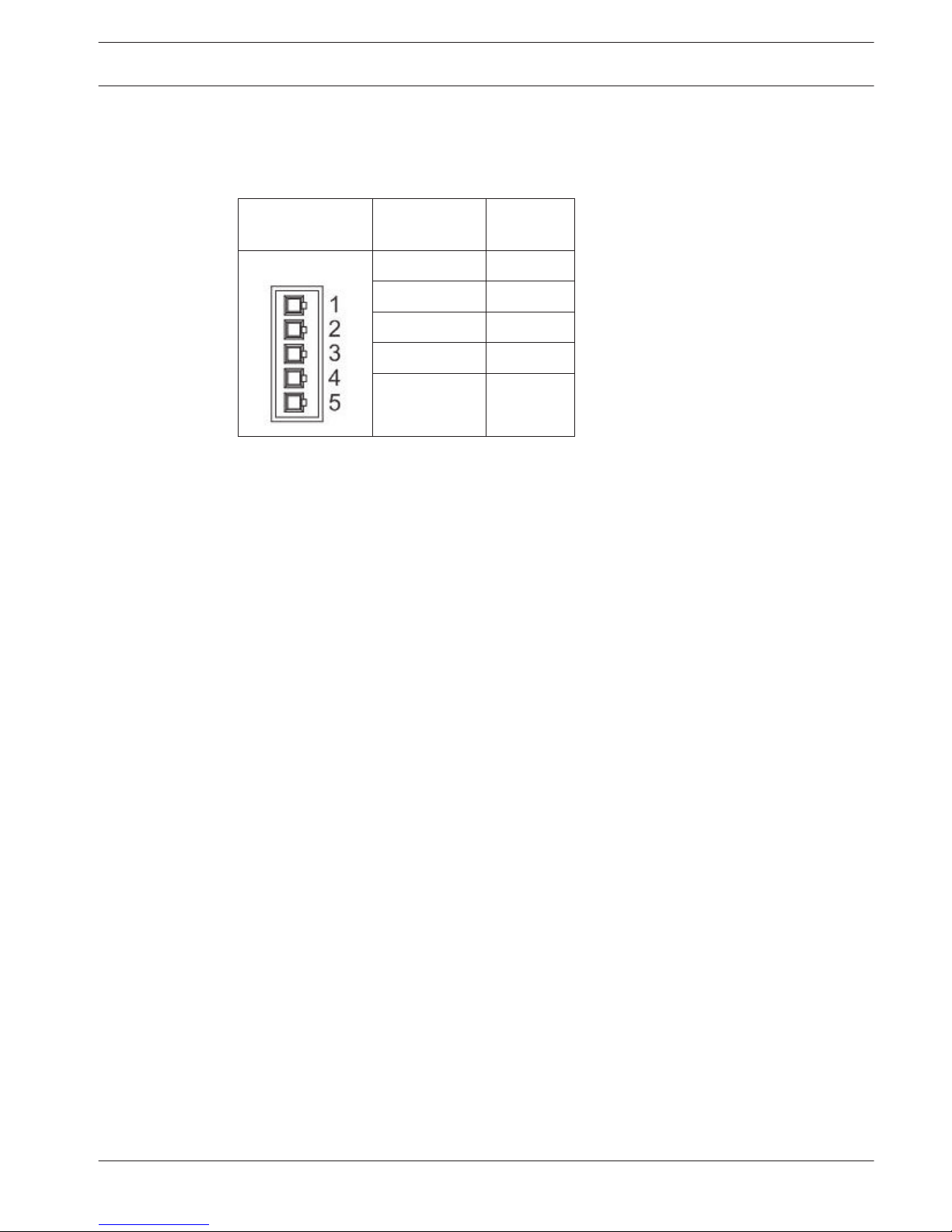
RS-485 Connector Definition
Before connecting the RS-485 wires, refer to the illustrations below for definition of the
RS-485 connector.
RS-485 Connector Switch
Number
Descriptio
n
SW1 R-
SW2 GND
SW3 R+
SW4 T-
SW5 T+
5.7
AUTODOME 5000 Analog PTZ Camera Connection | en 19
Bosch Security Systems, Inc. Operations Manual 2013.07 | 1.3 |
Page 20
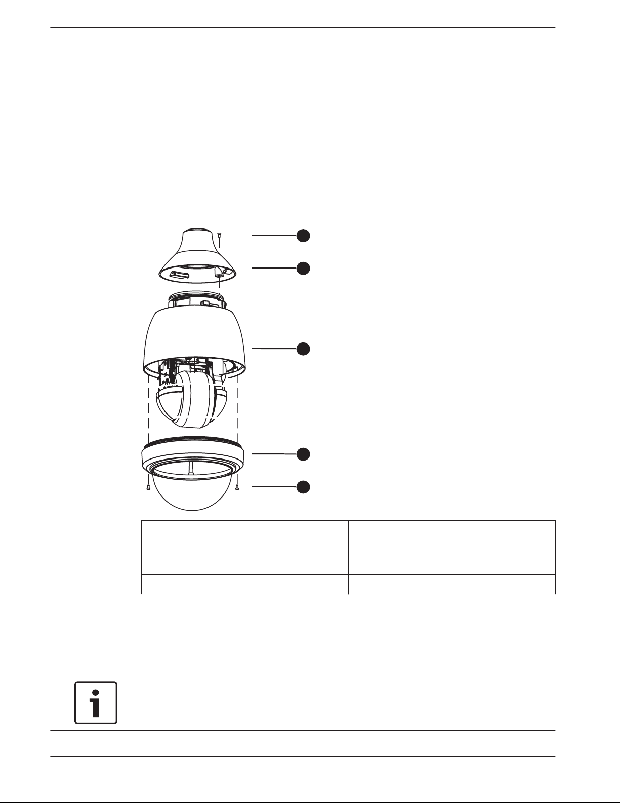
Prepare the Camera for Assembly
The camera is shipped with a PE cloth sheet covering the inside the dome cover and a lens
cap attached to the lens. Follow the steps below to remove them.
1. Loosen the screws from the top of the Dome Cover.
2. Rotate and detach the Dome Cover from the Dome Camera Body.
3. Remove the PE cloth sheet and take off the lens cap.
Assemble the Indoor Camera
Refer to the following illustration and descriptions for the assembly of the Indoor Dome
Camera.
1
2
3
4
5
1 M5x8L Mechanical Screw with Spring
washer (1 piece)
4 Bubble
2 Indoor Adaptor 5 M3x23L Screw with Rubber (2 pieces)
3 Dome Camera Body
Assembly Instructions
1. Attach the Bubble (4) to the Dome Camera Body (3) and fasten the M3x23L screws (5).
2. Attach the Indoor Adaptor (2) to the Camera Body (3) by turning clockwise and fasten the
M5x8L screw (1) after all cables are connected to the camera back plate.
Notice!
If the Dome Camera will be attached to a wall or a pipe mount, ensure that the Indoor
Adaptor is attached to the wall or pipe mount prior to attaching the Camera Dome Body.
5.8
5.9
20 en | Connection AUTODOME 5000 Analog PTZ Camera
2013.07 | 1.3 | Operations Manual Bosch Security Systems, Inc.
Page 21
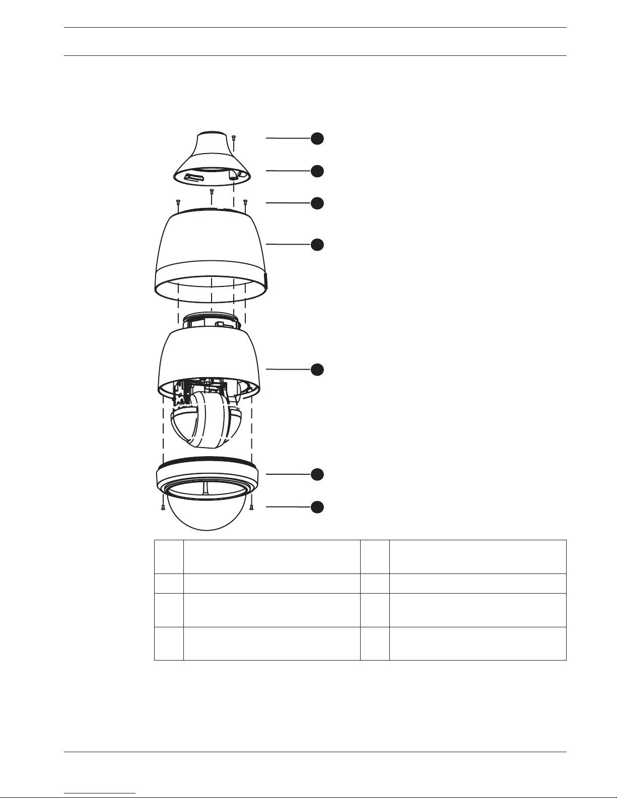
Assemble the Outdoor Camera
Refer to the following illustration and descriptions for the assembly of the Outdoor Dome
Camera.
1
2
3
4
5
6
7
1 M5x8L Mechanical Screw with Spring
Washer (1 piece)
4 Sunshield
2 Outdoor Adaptor 5 Camera Body
3 M4x21L Mechanical Screw with Spring
Washer (3 pieces)
6 Bubble
7 M3x23L Screws with Rubber (2
pieces)
5.10
AUTODOME 5000 Analog PTZ Camera Connection | en 21
Bosch Security Systems, Inc. Operations Manual 2013.07 | 1.3 |
Page 22

Assembly Instructions
1. Attach the Bubble (6) to the Camera Body (5) and fasten the two M3x23L screws (7).
2. Attach the Sunshield (4) to the Camera Body (5) by fastening the three (3) M4x21L
screws.
3. Attach the Outdoor Adaptor (2) to the Camera Body (5) by turning clockwise and fasten
the M5x8L screw (1) after all cables are connected to the camera back plate.
Notice!
If the Dome Camera will be attached to a wall or pipe mount, ensure that the Outdoor
Adaptor is attached to the wall or pipe mount prior to attaching the Camera Dome Body.
Accessories
The AUTODOME 5000 Series PTZ Dome camera comes with the hardware and installation
instructions necessary to mount the camera to a ceiling.
These following mounting accessories are available (and are supplied with separate mounting
instructions):
Model Number Description Application
VEZ-A5-WL Wall Mount Indoor/outdoor vertical walls
VEZ-A5-PP Pipe Mount Indoor/outdoor high ceilings
VEZ-A5-IC In-ceiling (Recessed)
Mount
Indoor drop-ceiling
VDA-CMT-PTZDOME Corner mount adapter Indoor/outdoor corner (used
with the VEZ-A5-WL Wall
Mount)
VDA-POMT-PTZDOME Pole mount adapter Indoor/outdoor mast (used
with the VEZ-A5-WL Wall
Mount)
!
Caution!
Installation
The installation should be made by qualified installation personnel and conform to the
National Electrical Code and applicable local codes.
Danger!
Servicing
TO REDUCE THE RISK OF ELECTRIC SHOCK, DO NOT PERFORM ANY SERVICING OTHER THAN
THAT CONTAINED IN THE OPERATING INSTRUCTIONS, UNLESS YOU ARE QUALIFIED TO DO
SO.
In USA and Canada, use Class 2 power supply unit (PSU) only.
5.11
22 en | Connection AUTODOME 5000 Analog PTZ Camera
2013.07 | 1.3 | Operations Manual Bosch Security Systems, Inc.
Page 23

Notice!
Use of Grounded Conduit
A grounded conduit is required in order to meet the EMC Regulation Requirements.
AUTODOME 5000 Analog PTZ Camera Connection | en 23
Bosch Security Systems, Inc. Operations Manual 2013.07 | 1.3 |
Page 24

On-Screen Display (OSD) Menu
The On-screen Display Setup Menu provides access to all programmable settings for the
camera.
Note: Although not always identified in the table below, most of the submenus have an Exit
option as well.
Camera Setup Menu
SUBMENU 1 SUBMENU 2 SUBMENU 3 VALUE
White Balance Auto
Indoor
Outdoor
ATW
Manual R Gain <000> to <127>
B Gain <000> to <127>
Video Level <1> to <15>
Auto SensUp Max <2x>, <4x>, <7.5x>,
<15x>, <30x>, <60x>,
<OFF>
Exposure Mode Auto
Shutter Shutter Speed PAL: < 1/50> to
<1/1000> sec.
NTSC: <1/60> to
<1/1000> sec.
Iris Value <Auto>
Gain Control <Auto>
Iris Shutter Speed <Auto>
Iris Value <1> to <17>
Gain Control Auto
Manual Shutter Speed PAL: < 1/50> to
<1/1000> sec.
NTSC: <1/60> to
<1/1000> sec.
Iris Value <1> to <17>
Gain Control <1> to <16>
Backlight ON, OFF
Sharpness <01> to <16>
WDR Function ON, OFF
Night Mode Threshold High, Mid, Low
6
6.1
24 en | On-Screen Display (OSD) Menu AUTODOME 5000 Analog PTZ Camera
2013.07 | 1.3 | Operations Manual Bosch Security Systems, Inc.
Page 25

SUBMENU 1 SUBMENU 2 SUBMENU 3 VALUE
Night Mode Auto, On, Off
Enhancement Zoom, Stabilize, Off
DNR 2D N.R. On, Off
3D N.R. On, Off
Restore Defaults
Exit
AUTODOME 5000 Analog PTZ Camera On-Screen Display (OSD) Menu | en 25
Bosch Security Systems, Inc. Operations Manual 2013.07 | 1.3 |
Page 26

Lens Setup Menu
SUBMENU 1 SUBMENU 2 SUBMENU 3 VALUE
Auto Focus Constant
Manual
Spot
Digital Zoom <Off>
<2x> to <12x>
Restore Defaults
Exit
6.2
26 en | On-Screen Display (OSD) Menu AUTODOME 5000 Analog PTZ Camera
2013.07 | 1.3 | Operations Manual Bosch Security Systems, Inc.
Page 27

PTZ Setup Menu
SUBMENU 1 SUBMENU 2 SUBMENU 3 VALUE
Autopan Autopan <1> to <4>
Start Point PT Move, To Save
End Point PT Move, To Save
Direction Right, Left
Speed <9°/sec>, <16°/sec>,
<21°/sec>, <32°/sec>
Dwell Time <000> to <127>,
Always
Run Autopan Enter
Tour Tour <1> to <8>
Record Start Enter
Record Ent Enter
Run Tour Enter
Preset Tour P. Tour <1> to <8>
P. Tour Point <1> to <64>
Preset Pos. <1> to <99>, End
Speed <1> to <15>
Dwell Time <0> to <127>, Always
Run P. Tour Enter
Preset Preset Set <1> to <99>
Preset Title
Overwrite
Clear
Preset Run <1> to <99>
Freeze On, Off
Home Setting Home Function On, Off
Select Mode Preset, P. Tour,
Autopan, Tour
Preset Point <1> to <99>
Preset Tour <1> to <8>
Autopan <1> to <4>
Tour <1> to <8>
6.3
AUTODOME 5000 Analog PTZ Camera On-Screen Display (OSD) Menu | en 27
Bosch Security Systems, Inc. Operations Manual 2013.07 | 1.3 |
Page 28

SUBMENU 1 SUBMENU 2 SUBMENU 3 VALUE
Return Time <005> to <099> sec.
or
<2>, <3>, <4>, <5>
min.
Schedule Switch On, Off
Point <1> to <32>
Hour <0> to <23>
Minute <0> to <59>
Mode None, Preset, P. Tour,
Autopan, Tour, Night
Mode, Tracking
Mode Line None
Preset <1> to <99>
Preset Tour <1> to <8>
Autopan <1> to <4>
Tour <1> to <4>
Night Mode Auto, On
Tracking On, Off
Schedule Reset
Misc Function Angle Adjuster Min Angle <-10> to <+10>
Max Angle <80> to <100>
PT Position PT Display On, Off
Set Pan Zero Enter
Speed By Zoom On, Off
AutoCali On, Off
Restore Defaults
Exit
28
en | On-Screen Display (OSD) Menu AUTODOME 5000 Analog PTZ Camera
2013.07 | 1.3 | Operations Manual Bosch Security Systems, Inc.
Page 29

Display Setup Menu
SUBMENU 1 SUBMENU 2 SUBMENU 3 VALUE
ID Display On, Off
Title Display Title Display On, Off
Title Setting <01> to <16>
Privacy Masking Privacy Switch On, Off
Transparency On, Off
Color Black, White, Red,
Green, Blue, Cyan,
Yellow, Magenta
Set Masking <1> to <20>
Center L/R
Size: H Size <000> to <080>
Size: V Size <000> to <060>
Clear Masking <01> to <20>
Time Setting Time Display On, Off
Set Year <2000> to <2099>
Set Month <01>to <12>
Set Day <01> to <31>
Set Hour <00> to <23>
Set Minute <00> to <59>
Motion Track Motion Track On, Off
Motion Block On, Off
Bounding Box On, Off
Threshold <1> to <255>
Restore Defaults
Exit
6.4
AUTODOME 5000 Analog PTZ Camera On-Screen Display (OSD) Menu | en 29
Bosch Security Systems, Inc. Operations Manual 2013.07 | 1.3 |
Page 30

Alarm Setup Menu
SUBMENU 1 SUBMENU 2 SUBMENU 3 VALUE
Alarm Setting Alarm Pin <01> to <04>
Alarm Switch On, Off
Alarm Type <NO> (NORMAL OPEN),
<NC> (NORMAL CLOSE)
Alarm Action Preset, Preset Tour,
Autopan, Tour
Preset Point <01> to <99>
P. Tour <01> to <08>
Autopan <01> to <04>
Tour <01> to <08>
Dwell Time Always,
<001> to <127> (Sec.)
Alarm Priority <01> to <04>
Alarm Output 1, 2, 1+2, Off
Alarm Detect Motion Detection On, Off
Block Mode On, Off
Frame Set <01> to <04>
Left Limit L/R
Top Limit U/D
H. Size +/-
V. Size +/-
Mode Preset, P. Tour,
Tour, Autopan
Frame Disable <01> to <04>
Threshold <001> to <255>
Restore Defaults
Exit
6.5
30 en | On-Screen Display (OSD) Menu AUTODOME 5000 Analog PTZ Camera
2013.07 | 1.3 | Operations Manual Bosch Security Systems, Inc.
Page 31

Language Setup Menu
SUBMENU 1 SUBMENU 2 SUBMENU 3 VALUE
EN
DE
FR
ES
NL
IT
PL
PT
RU
ZH-ZN
Exit
6.6
AUTODOME 5000 Analog PTZ Camera On-Screen Display (OSD) Menu | en 31
Bosch Security Systems, Inc. Operations Manual 2013.07 | 1.3 |
Page 32

Installer Menu
SUBMENU 1 SUBMENU 2 SUBMENU 3 VALUE
System Setup System Reset System Reset
Initialize Camera
Password On, Off
Image Inverse On, Off
Flip Off, M.E., Image
OSD Auto Close Off, <10>, <15>, <20>,
<25>, <30>, <60>,
<90>, <120> sec.
Camera Setting ID Setting Setting Type HW, OSD
ID Number <01> to <99>
Title Setting Enter
Protocol OSRD, Pelco P,
Pelco D
Baud Rate <2400>, <4800>,
<9600>
ID Info. ID Number, Title,
Protocol, Baud Rate
Restore Defaults
Exit
6.7
32 en | On-Screen Display (OSD) Menu AUTODOME 5000 Analog PTZ Camera
2013.07 | 1.3 | Operations Manual Bosch Security Systems, Inc.
Page 33

Monitor Display
The information shown on the screen is classified in terms of displaying position, function,
OSD display and description, as shown in the table below.
Position Function OSD Display Description
1 Motion MOTION Alarm Detect Message
2 Alarm ALARM 1 Alarm Message
3
Focus Modes &
Backlight
A Auto Focus Mode
M Manual Focus Mode
X Back Light Compensation OFF
B Back Light Compensation ON
4
Booting Message XX…(Dome Type);
ID: 001 (Default)
DSCP/9600 (Default)
INITIALIZING
Dome Type, ID Address, Protocol and
Baud Rate
5
Error Message PAN ERROR /
TILT ERROR /
CAM MODULE ERROR
System initializing error message
6 Zoom Ratio x1 Present Zoom Ratio
(Optical Zoom/Digital Zoom)
7 Title Maximum 20 characters for each title.
16 sets of title are available.
8 Camera ID c Camera ID
6.8
AUTODOME 5000 Analog PTZ Camera On-Screen Display (OSD) Menu | en 33
Bosch Security Systems, Inc. Operations Manual 2013.07 | 1.3 |
Page 34

Position Function OSD Display Description
9 Time XXXX/XX/XX XX:XX Year/Month/Day Hour: Minute
10
Position display XX YYY/YY XX: facing direction of PTZ
(N, E, Z, W, NE, SE, SW, SN)
YYY/YY: angle of PZT, 0 ~ 359 / 10 ~ −90
When the camera is starting up, the OSD Start Page will display information including ID
number, protocol / baud rate, and camera initializing message. When any camera error occurs,
the error message(s) will be shown on the screen.
34 en | On-Screen Display (OSD) Menu AUTODOME 5000 Analog PTZ Camera
2013.07 | 1.3 | Operations Manual Bosch Security Systems, Inc.
Page 35

Main Menu
When you use Pelco-D and Pelco-P protocol with your controller, you can access the MAIN
MENU on your monitor by pressing the keys [95] + [Preset], or by pressing and holding the
[Menu] key for 2 seconds.
When you use Bosch OSRD protocol with your controller, you can access the MAIN MENU on
your monitor by pressing the keys [ON]+[46]+[Enter].
MAIN MENU
CAMERA SETUP
LENS SETUP
PTZ SETUP
DISPLAY SETUP
ALARM SETUP
LANGUAGE
INSTALLER MENU
RESTORE DEFAULTS
EXIT
Table 6.1: Main Menu
MAIN MENU Choices
Menu
Description
Exit Exits the menu.
Camera Setup Accesses adjustable camera settings such as: focus/zoom, white
balance, exposure, day/night, sharpness and backlight, WDR/DNR.
Lens Setup
PTZ Setup Accesses adjustable pan/tilt/zoom (PTZ) settings such as: preset
speed, autoflip, proportional pan/tilt, home preset, and calibration.
Display Setup Accesses adjustable display settings such as: OSD, privacy zone
masking, image setup, motion/face detection, and display
language.
Alarm Setup Accesses the alarm settings such as: inputs, outputs, and rules.
Language
Installer Menu
Restore Defaults
SYSTEM SETUP Accesses system information and actions such as: rebooting,
resetting default settings, setting or resetting passwords.
6.9
AUTODOME 5000 Analog PTZ Camera On-Screen Display (OSD) Menu | en 35
Bosch Security Systems, Inc. Operations Manual 2013.07 | 1.3 |
Page 36

Common Menus
Exit
Exit the menu.
Restore Defaults
The RESTORE DEFAULTS menu is for restoring the settings in any of the menus to the factory
default values. Select <YES> to reset the parameters.
6.9.1
36 en | On-Screen Display (OSD) Menu AUTODOME 5000 Analog PTZ Camera
2013.07 | 1.3 | Operations Manual Bosch Security Systems, Inc.
Page 37

Camera Setup
The Camera Setup menu is as shown below:
CAMERA SETUP
WHITE BALANCE
VIDEO LEVEL
AUTO SENSUP MAX
EXPOSURE MODE
BACKLIGHT
SHARPNESS
WDR FUNCTION
NIGHT MODE
ENHANCEMENT
DNR
RESTORE DEFAULTS
EXIT
White Balance
A digital camera needs to find reference to color temperature, which is a way of measuring the
quality of a light source, for calculating all the other colors. The unit for measuring this ratio is
in degrees Kelvin (K). You can select one of the White Balance Control modes according to the
condition. The following table shows the color temperature of some light sources.
Light Sources Color Temperature in Degrees Kelvin
(K)
Cloudy Sky 6,000 to 8,000
Noon Sun and Clear Sky 6,500
Household Lighting 2,500 to 3,000
75-watt Bulb 2,820
Candle Flame 1,200 to 1,500
Auto
In this mode, white balance works within its color temperature range. This mode computes
the white balance value output using color information from the entire screen. It outputs the
proper value using the color temperature radiating from a black subject based on a range of
values from 3000K to 7500K.
Indoor
3200 K Base mode.
Outdoor
5800 K Base mode.
6.10
6.10.1
AUTODOME 5000 Analog PTZ Camera On-Screen Display (OSD) Menu | en 37
Bosch Security Systems, Inc. Operations Manual 2013.07 | 1.3 |
Page 38

ATW
In Auto Tracking White Balance (ATW) mode, the camera takes out the signals in a screen in
the range from 2000 K to 10,000 K.
Manual
In this mode, you can change the White Balance value manually. R Gain and B Gain are
adjustable and range from <000> to <127>.
MANUAL
R Gain 010
B Gain 019
Exit + Save YES
Video Level
Adjust the video level from <1> to <15> (−10.5 dB to 10.5 dB). Select <OFF> to disable the
function.
AutoSensUp Max
You can set up the limit for sensitivity when the shutter speed is selected as Auto SensUp.
This function will determine how long the image sensor is exposed to light, so that you can
see clear images in dark environments. The setting values are 2x, 4x, 7.5x, 15x, 30x, 60x and
off. The camera will adjust the shutter speed automatically, based on the light condition of the
environment. You will be able to see objects in darkness below 0.1 lux.
Exposure Mode
Exposure is the amount of light received by the image sensor and is determined by the width
of lens diaphragm opening (iris adjustment), the amount of exposure by the sensor (shutter
speed) and other exposure parameters. With this item, you can a preferred exposure mode.
Auto
In this mode, the camera’s Bright Value, Shutter Speed, Iris Value and Gain Control are
determined automatically to get consistent video output level.
Shutter
In this mode, shutter speed takes main control of exposure, and both the iris value and gain
control function automatically in cooperation with shutter speed to achieve consistent
exposure output. The shutter speed ranges from 1/10000 to 1/50 for PAL and 1/10000 to 1/60
for NTSC.
Iris
In this mode, the Iris function adjusts exposure in higher property. Shutter speed and gain
control circuit function automatically in cooperating with Iris to get consistent exposure
output. The iris value can be set from <1> to <17> (F1.6 to F28).
Manual
In this mode, you can adjust the following values for optimized video output:
– Shutter speed (1/10000 to 1/50 for PAL; 1/10000 to 1/60 for NTSC)
– Iris value <1> to <17> (F1.6 to F28)
– Gain control <1> to <16> (−3 dB to 28 dB)
6.10.2
6.10.3
6.10.4
38 en | On-Screen Display (OSD) Menu AUTODOME 5000 Analog PTZ Camera
2013.07 | 1.3 | Operations Manual Bosch Security Systems, Inc.
Page 39

Backlight
The backlight compensation function helps to improves image quality when the background
illumination level is high. Select <ON> to activate the function. The center object will be
brightened in contrast to the edge of the picture (where a backlight would be most likely
located).
Sharpness
In this menu, you can adjust enhancement of the edges of objects in the picture. There are 16
levels of adjustment: <01> to <16>. <01> represents “no enhancement”. This function can help
to make the image sharper to read texts.
WDR Function
The Wide Dynamic Range (WDR) function is especially effective in solving indoor and outdoor
contrast issues to enhance better image quality and video display. It enables the camera to
catch detailed data from the dark part (Indoor) without any saturation from the bright part
(Outdoor).
Select <ON> to activate the WDR function. The camera will operate the WDR function
automatically. Select <OFF> to deactivate.
Night Mode
With the IR cut filter, the camera can still catch clear images at night time or in low light
conditions. During day time, the IR cut filter will be on to block the infrared light for clear
image. During night time, the IR cut filter will be removed to catch infrared light, and the
displayed images will become black and white.
Threshold
The Internal circuit will automatically decide the occasion to remove the IR cut filter according
to the value of light condition calculated by the internal light algorithm. The options include
<LOW>, <MID> and <HI>. <LOW> indicates a higher sensitivity and can improve reliability of
lens so that it is easier to switch to Day mode and relatively difficult to change to Night mode.
<HI> indicates that it is easier to switch to Night mode and difficult to change to Day mode.
Night Mode
Select <AUTO> to let the camera switch ON/OFF the IR cut filter automatically according to
detection of light condition. Otherwise, select <ON> to remove the IR cut filter and the camera
will be in Night mode. Select <OFF> to attach the IR cut filter and the camera will be in Day
mode to disable the IR function.
Enhancement
With the Enhancement function, the "digital enhancement" will be implemented to improve
the zoom performance, which can capture images that would otherwise be blurred due to
vibration. The default setting is <ZOOM>, which gradually activates digital zoom when optical
zoom is greater than 1x. However, the Image Enhancement feature is set to OFF due to DSP
limitation.
When <STABILIZE> is selected, the Image Enhancement is activated. Under this mode, digital
zoom is added and the image is stabilized.
If you select <OFF>, digital zoom and Image Enhancement are deactivated.
DNR
In this menu, you can select the parameters for Dynamic Noise Reduction (DNR): 2DNR or
3DNR.
6.10.5
6.10.6
6.10.7
6.10.8
6.10.9
6.10.10
AUTODOME 5000 Analog PTZ Camera On-Screen Display (OSD) Menu | en 39
Bosch Security Systems, Inc. Operations Manual 2013.07 | 1.3 |
Page 40

With 2D / 3D Digital Noise Reduction (D.N.R.), the processor analyzes pixel by pixel and frame
by frame to eliminate environmental noise signal so that the highest quality image can be
produced even in low light conditions. In comparison with 2D D.N.R., 3D D.N.R. generates
better de-noising effects.
Lens Setup
The Lens Setup menu is as shown below.
LENS SETUP
AUTO FOCUS
DIGITAL ZOOM
RESTORE DEFAULTS
EXIT
Auto Focus
The focus of the camera can be set in three different modes: Constant, Manual and Spot.
Constant
Select <CONSTANT> and the camera will adjust the focus automatically and continuously in
any condition.
Manual
Select <MANUAL> to adjust the focus manually via the control keyboard.
Spot
When <SPOT> is selected, the camera will only activate Auto Focus after it stops movement.
Once the camera is focused, Auto Focus is inactive until the camera moves again.
Digital Zoom
You can enable Digital Zoom from <2x> to <12x>. The Digital Zoom will be activated after the
full Optical Zoom level is reached. The default setting is <OFF>.
Notice!
The difference between optical and digital zoom is that optical zoom uses the lens within the
camera to draw the image closer via zoom in or out to achieve the desired effect. Optical
zoom remains the same quality and full resolution of the zoomed image. On the other hand,
Digital zoom takes a portion of an image and expands the partial image to the full size of the
original image. Therefore, the image quality will be reduced.
PTZ Setup
The PTZ Setup menu is as shown below:
PTZ SETUP
AUTOPAN
TOUR
PRESET TOUR
PRESET
FREEZE
6.11
6.11.1
6.11.2
6.12
40 en | On-Screen Display (OSD) Menu AUTODOME 5000 Analog PTZ Camera
2013.07 | 1.3 | Operations Manual Bosch Security Systems, Inc.
Page 41

PTZ SETUP
HOME SETTING
SCHEDULE
MISC FUNCTION
RESTORE DEFAULTS
EXIT
Autopan
Autopan means the motion of scanning an area horizontally so that the camera can catch the
horizontal view. The parameters are as follows.
AUTOPAN
Autopan 01
Start Point PT Move
End Point PT Move
Direction Right
Speed 9° sec.
Dwell Time 001
Run Autopan Enter
Exit YES
Autopan
There are four sets of Autopan Lines built into the camera. You can select a line to execute by
pressing LEFT/RIGHT direction keys. In addition, you can command the camera to do endless
panning by setting the start point the same as the end point.
Start Point
Follow the description below to set the start position of the AUTOPAN path.
1. Move the cursor to <START POINT> and press <CAMERA MENU> while the item, <PT
MOVE>, is flashing. Then the item will turn <TO SAVE> automatically.
2. Point the camera lens to a desired position and press <CAMERA MENU> to save the
position as the start point. The cursor will move to <END POINT> automatically. Be sure
to set the end point to complete Auto Pan setting.
Notice!
The tilt and zoom values of the start point will be recorded and fixed for the selected
Autopan line.
End Point
You can set the end point after the start point is defined. Pan the camera lens to another
position and press <CAMERA MENU> to save the position as the end point.
Direction
You can set the AUTOPAN direction of the camera. The camera will start to pan clockwise from
the start point to the end point if <RIGHT> is selected here, and then return to the start point.
The camera will start to pan anti-clockwise from the start point to the end point if the
selection is <LEFT>. Refer to the diagram below.
6.12.1
AUTODOME 5000 Analog PTZ Camera On-Screen Display (OSD) Menu | en 41
Bosch Security Systems, Inc. Operations Manual 2013.07 | 1.3 |
Page 42

1 Camera
2 LEFT (counterclockwise) selection
3 RIGHT (clockwise) selection
4 Start point
5 End point
Speed
You can define the rotation speed during Autopan. The speed is adjustable from 9°/sec., 16°/
sec, 21°/sec. or 32°/sec.
Dwell Time
The dwell time is the duration of time that the camera remain at an Autopan line, and the
range is from <000> to <127> seconds. The camera proceeds to the next Autopan line when
the dwell time expires. If the setting is <000>, the camera remains at this Preset Tour Point for
less than 1 second and then shifts to the next point.
Run Autopan
Select this item to run the Autopan function after all Autopan settings are complete. Press the
<CAMERA MENU> key to run the Autopan path.
Notice!
You can execute the Autopan function through a control keyboard. Refer to the control
keyboard’s quick guide for further information.
Tour
Tour is a route formed with manual operation, through adjusting pan, tilt position and zoom
parameters, which can be stored and recalled to execute repeatedly.
TOUR
Tour 01
Record Start Enter
Record End Enter
6.12.2
42 en | On-Screen Display (OSD) Menu AUTODOME 5000 Analog PTZ Camera
2013.07 | 1.3 | Operations Manual Bosch Security Systems, Inc.
Page 43

TOUR
Run Tour Enter
Exit YES
Tour
Up to eight sets of Tour routes can be created for one camera. Use the LEFT/RIGHT direction
keys to select a set first and then follow the steps below to start recording the Tour route.
Record Start
Follow the description below to record the TOUR route.
1. Rotate the camera to a desired view area (for some protocols, you may need to do it
before entering the OSD), and press <CAMERA MENU> to build the tour path using the
joystick on the control device. The percentage of the memory buffer used will be
displayed on the screen.
2. Pan, tilt and zoom the camera to form a path.
Notice!
Beware of the memory size when building a Tour route. Once the buffer percentage reaches
100%, recording stops.
Record End
The cursor moves to RECORD END while building the Tour route. When the setting is
completed, press <CAMERA MENU> to save the route.
Run Tour
Press the <CAMERA MENU> key (ENTER) to run the defined Tour path after tour setting is
complete.
Notice!
You can execute the Tour function through a control keyboard. Refer to the control
keyboard’s quick guide for further information.
Preset Tour
This function executes pre-positioning of the pan, tilt, zoom and focus features in a certain
preset tour for a camera. Before setting this function, you must pre-define at least two preset
points.
PRESET TOUR
P. Tour 01
P. Tour Point 01
Preset Pos. 01
Speed 01
Dwell Time 000 Sec.
Run P. Tour Enter
Exit YES
Preset Tour
There are eight sets of preset tour built in the camera. Use the LEFT/RIGHT direction keys to
select a set first and then set its preset tour points.
6.12.3
AUTODOME 5000 Analog PTZ Camera On-Screen Display (OSD) Menu | en 43
Bosch Security Systems, Inc. Operations Manual 2013.07 | 1.3 |
Page 44

Preset Tour Point
Up to 64 points can be setup for each Preset Tour. The Preset Tour Points represent order of
the preset points that the camera will run automatically. The following setup items, including
PRESET POSITION, SPEED and DWELL TIME influence how the camera runs through each
preset tour point.
Preset Position
Assign a specific preset position to the selected Preset Tour Point . Options include <1> to
<99> and <END>. END is used for the Preset Tour Point following the last Preset Tour Point
when the amount of preset tour points (the previous menu item) is less than 64.
Notice!
If you will not use all 64 points, set the point following the last Preset Tour Point as <END> so
that the preset tour can work properly. For example, if you intend to set a Preset Tour with 5
preset tour points, you must set the PRESET POSITION of Preset Tour Point 06 as <END>.
!
Warning!
To set more than one Preset Tour Point or Preset Position, you must exit the Preset Tour
menu and access it again to set the next Point or Position.
Speed
You can set the pan/tilt speed of the camera from one Preset Tour Point to the next, and the
range of setup speed is from 1 to 15. Within the range, PAN speed varies from 10 to 360
(degree/sec.), and TILT speed varies from 8 to 360 (degree/sec.).
Dwell Time
The Dwell Time is the duration of time that the camera will stay at a Preset Tour Point, and the
range is from <000> to <127> seconds. The camera will go to the next preset tour point when
the Dwell Time expires. If the setting is <000>, the camera will stay at this Preset Tour Point
for less than 1 second and then shift to the next point.
Currently, the default dwell time is 0 seconds. You must change the numeral to set any other
duration of dwell time.
Run Preset Tour
You can command the camera to run the selected Preset Tour manually. Press the <CAMERA
MENU> key to execute a preset tour.
Notice!
You can execute the Preset Tour function through a control keyboard. Refer to the control
keyboard’s quick guide for further information.
Preset
You can define preset points in this menu.
PRESET
Preset Set 01
Preset Run 01
Exit YES
6.12.4
44 en | On-Screen Display (OSD) Menu AUTODOME 5000 Analog PTZ Camera
2013.07 | 1.3 | Operations Manual Bosch Security Systems, Inc.
Page 45

Preset Set
A total of 99 preset points can be set. Follow the steps below.
1. Press the LEFT/RIGHT direction keys to select a number (01 represents preset point 1, 02
represents preset point 2, etc.).
2. Press the <CAMERA MENU> key and then move the camera to a targeted shooting area/
point.
3. Press the <CAMERA MENU> key again to save the defined preset point.
4. Once the preset point is saved, access the <CAMERA MENU> again to choose one of the
following options: <PRESET TITLE> (name the preset point), <OVERWRITE> (overwrite
the preset number with the current point), <CLEAR> (clear the saved preset point) and
<EXIT> (exit without change).
5. Select <PRESET TITLE> to name the preset point, up to 20 characters. The camera
displays a keyboard similar to the illustration below.
Choose a character with the direction keys and press the <CAMERA MENU> key to
choose the character.
To delete characters in a title, move the cursor to the <LEFT> or the <RIGHT> and press
<CAMERA MENU> to select a character in the entry field. Then move the cursor to
<DELETE> and press <CAMERA MENU> to delete the selected character.
Move the cursor to <SAVE> and press <CAMERA MENU> to accept and save the title.
6. To overwrite a previous position, move to the new position and choose <OVERWRITE>
from the submenu.
7. To clear the saved preset point, enter the submenu and select <CLEAR> (clears both
preset point).
Preset Run
Press the <CAMERA MENU> key, and the camera will go to the selected point. To run other
defined preset points, press the LEFT/RIGHT direction keys, select the preset point that you
want to go, and press the <CAMERA MENU> key again.
Notice!
You can set preset points through a control keyboard. Refer to the control keyboard’s quick
guide for further information.
AUTODOME 5000 Analog PTZ Camera On-Screen Display (OSD) Menu | en 45
Bosch Security Systems, Inc. Operations Manual 2013.07 | 1.3 |
Page 46

Freeze
Freeze function allows you to hold the image while the camera is moving between preset
positions such as in PRESET and PRESET TOUR modes. For example, when the camera is
manipulated to run from point A to point B, if the Freeze function is activated, the first view
that you would see is point A. Then the next view would directly change to point B without
displaying the moving path.
Home Setting
You can set an operation mode to ensure constant monitoring. If the camera idles for a period
of time, the selected function will be activated automatically. That is the HOME function. The
HOME function helps to provide constant and accurate monitoring, which prevents the camera
from idling or missing events.
HOME SETTING
Home Function Off
Select Mode Preset
Preset Point 01
Return Time 005 Sec
Go Enter
Exit YES
Home Function
You can enable or disable the HOME function. Use the LEFT/RIGHT direction keys to change
the setting.
Select Mode
Select one of the modes that the camera should execute when the HOME function is enabled
and the RETURN TIME expires. The options include <PRESET>, <PRESET TOUR>, <AUTOPAN>
and <TOUR>. Use the LEFT/RIGHT direction keys to change the setting, and the menu items
below will change in cooperating with the selection.
Preset Point
Select a preset point the dome should go to after the Return Time function, which will be
mentioned later, is activated. The preset point(s) should be set prior either in the PRESET
setup menu or through the keyboard.
Preset Tour
Select a preset tour line that the camera should execute after the Return Time function is
activated. The preset tour line(s) should be defined prior either in the PRESET TOUR setup
menu or through the keyboard.
Autopan
Select an Auto Pan line that the camera should execute after the Return Time function is
activated. The Auto Pan line(s) should be defined prior either in the AUTOPAN setup menu or
through the keyboard.
Tour
Select a tour line that the camera should execute after the Return Time function is activated.
The tour line(s) should be defined prior either in the TOUR setup menu or through the
keyboard.
6.12.5
6.12.6
46 en | On-Screen Display (OSD) Menu AUTODOME 5000 Analog PTZ Camera
2013.07 | 1.3 | Operations Manual Bosch Security Systems, Inc.
Page 47

Return Time
The camera starts to count down RETURN TIME when the dome idles, and then execute the
SELECT MODE function when the return time is up. The RETURN TIME ranges from 5 to 99
seconds or 2, 3, 4, or 5 minutes.
Go
If the HOME function is enabled, select this parameter to execute the HOME.
Schedule
You can use the schedule function to program a preset point or function (Preset Tour / Auto
Pan / Tour) to be executed automatically at a specific time.
SCHEDULE
Switch Off
Point 01
Hour 00
Minute 00
Mode None
No Action None
Schedule Reset Yes
Exit YES
Switch
Select <ON> to enable or <OFF> to disable the schedule function.
Point
You can arrange 32 sets of schedule points. Each set of schedule point can be assigned one
kind of schedule modes.
Hour / Minute
These items are for setting up the time to execute each schedule point.
Mode
This is for setting the schedule function of the selected schedule point. The options are listed
as follows. For options other than <NONE>, further setting of <MODE LINE> is required.
– None
No action will be executed for the schedule point.
– Preset
You can select <PRESET > as an action carried out in a schedule point.
– Preset Tour
You can select <PRESET TOUR> as an action carried out in a schedule point.
– Autopan
You can select <AUTOPAN LINE> as an action carried out in a schedule point.
– Tour
You can select <TOUR LINE> as an action carried out in a schedule point.
– Night Mode
If < NIGHT MODE > is selected, the Night Mode function is activated for a schedule point.
– Tracking
You can select <MOTION TRACK> as an action carried out in a schedule point.
6.12.7
AUTODOME 5000 Analog PTZ Camera On-Screen Display (OSD) Menu | en 47
Bosch Security Systems, Inc. Operations Manual 2013.07 | 1.3 |
Page 48

Mode Line
After you select a schedule function for MODE, you can specify the MODE LINE of the selected
schedule function. According to different schedule functions, options for MODE LINE will be
different.
Schedule Reset
You can reset the whole schedule setting with this item.
Misc. Function
You can set up some miscellaneous functions here.
MISC FUNCTION
Angle Adjuster Enter
PT Position Enter
Speed By Zoom Off
Auto Cali. Off
Exit YES
Angle Adjuster
You can adjust the range of tilt motion by defining the angles between which the camera tilts.
The minimum range is from −10° to 10°. The maximum range is from 80° to 100°. The default
tilt angle is 90°.
PT Position
PT Position can setup the display of the Pan/Tilt position of the camera on the screen. Refer
to section Monitor Display, page 33 for the displaying location.
– PT Display
Set this item to <ON> to enable the display of the pan/tilt position on the screen. The
display format will be “XX YYY/ YY”.
– Set Pan Zero
By using <SET PAN ZERO> function, you can set the North as coordinate zero.
The display will show eight different directions including N, E, S, W, NE, SE, SW and SN,
depending on the closest direction that the camera is facing. The PAN range is from 0° to
359°, and the TILT range is from 10° to −90°. Once the TILT degree is lower than −90°,
the PAN degree will automatically be added 180°.
Speed By Zoom
If this item is set to <ON>, the pan/tilt speed will be adjusted automatically by internal
algorithm when zooming. The larger zoom ratio leads to the lower rotating speed.
Auto Cali. (Auto Calibration)
Each camera has one horizontal point and one vertical infrared rays check point. During
installation or maintenance, the camera’s position may be moved. Therefore, the relative
distance between the original set point and the check point will be changed. If the Auto
Calibration function is enabled, the camera will automatically detect the matter and reset the
horizontal point back to the original position.
Display Setup
The Display Setup menu is as shown below:
6.12.8
6.13
48 en | On-Screen Display (OSD) Menu AUTODOME 5000 Analog PTZ Camera
2013.07 | 1.3 | Operations Manual Bosch Security Systems, Inc.
Page 49

DISPLAY SETUP
ID DISPLAY
TITLE DISPLAY
PRIVACY MASKING
TIME SETTING
MOTION TRACK
RESTORE DEFAULTS
EXIT
ID Display
You can decide whether the camera’s ID will be displayed on the screen for the purpose of
identifying the camera.
Select <ON> to enable the display of the ID address of the camera on the screen. Alternatively,
select <OFF> to hide the ID address of the camera.
Title Display
You can choose whether to display the predefined titles of the selected positions on the
screen.
TITLE DISPLAY
Title Display Off
Title Setting 01
Exit YES
Title Display
Select <ON> to display the titles when the camera is shooting at the titled positions. Select
<OFF> to hide the titles, even they have been predefined.
Title Setting
Up to 16 scene titles can be set with maximum 20 characters for each title. Follow the steps
below to set a camera title.
1. Operate the camera to a position where you want to set a title for it.
2. Access the OSD and go to <DISPLAY SETUP> → <TITLE DISPLAY> →<TITLE SETTING>.
3. Select a number to represent the position.
4. Press the <CAMERA MENU> key on the keyboard to access the editing page.
6.13.1
6.13.2
AUTODOME 5000 Analog PTZ Camera On-Screen Display (OSD) Menu | en 49
Bosch Security Systems, Inc. Operations Manual 2013.07 | 1.3 |
Page 50

5. Choose a character with direction keys and then press the <CAMERA MENU> key to
input. For example: <A> <CAMERA MENU>, <B> <CAMERA MENU>, <C> <CAMERA
MENU>. The title is ABC.
6. To delete input characters, move the cursor to <LEFT> or <RIGHT> and press <CAMERA
MENU> to select a character in the entry field. Then move the cursor to <DELETE> and
press <CAMERA MENU> to delete the selected character.
7. When the setting is completed, move the cursor to <SAVE> and press <CAMERA MENU>
to save.
Privacy Masking
The Privacy Masking function aims to avoid any intrusive monitoring. You can adjust the
camera position by the joystick, and adjust the masking size and area via the direction keys.
When setting a mask, it is best to set it at least twice as large (height and width) as the
masked object. The camera will assume the center of the selected view as a starting point,
and the joystick will be locked as you enter the <SET MASKING> menu.
Notice!
The Image Flip function and the Image Inverse function will be disabled automatically while
the Privacy Masking function is enabled. Refer to the section System Setup, page 57.
The available area for setting a privacy mask is restricted within tilt angle 70°. Maximum 20
masks can be displayed in one scene. When Motion Detection function is enabled, only 16
masks zones can be displayed.
PRIVACY MASKING
Privacy Switch Off
Transparency Off
Color Black
Set Masking 01
Clear Masking 01
Exit YES
Privacy Switch
You can enable or disable the Privacy Masking function through this item. Set this item to
<ON> before configuring mask zones.
6.13.3
50 en | On-Screen Display (OSD) Menu AUTODOME 5000 Analog PTZ Camera
2013.07 | 1.3 | Operations Manual Bosch Security Systems, Inc.
Page 51

Transparency
The privacy masks can be set as transparent. Select <ON> to display transparent masks.
Color
Colors of privacy masks can be set via this item. The available colors are black, white, red,
green, blue, cyan, yellow and magenta.
Set Masking
Use the control device to move the camera to the area where you want to set a mask. Press
<CAMERA MENU> to enter the SET MASK menu. The camera will memorize the current
position as a privacy masking position.
SET MASKING
Center Enter
Size Enter
Exit + Save YES
– Center
The original center of a mask zone is the center of a screen. It is possible to move a mask
zone to other positions by adjusting with the LEFT/RIGHT keys. The camera will pan to
the right or to the corresponding direction according to users’ control.
– Size
You can adjust the horizontal / vertical size of a privacy mask through this item. Setting
the H size and V size to 0 will delete the selected mask.
Clear Masking
You can delete a preset masking zone with this item. Select a target masking zone and press
<CAMERA MENU> to confirm the deletion.
Time Setting
The Time Setting function is used to set the time-related parameters of the camera. The menu
is as follows.
TIME SETTING
Time Display Off
Set Year 2012
Set Month 09
Set Day 01
Set Hour 00
Set Minute 00
Exit + Save YES
Time Display
Select <ON> to enable the display of time information on the screen, or select <OFF> to
disable.
Set Year / Month / Day
These items are for setting up the system date.
Set Hour / Minute
These items are for setting up the system time.
6.13.4
AUTODOME 5000 Analog PTZ Camera On-Screen Display (OSD) Menu | en 51
Bosch Security Systems, Inc. Operations Manual 2013.07 | 1.3 |
Page 52

Motion Track
Motion Track consists of algorithms that detect movements or changes to see whether the
movements or changes mean a possible threat is about to occur or is occurring. These
algorithms work by examining each pixel of the video and putting together all the pixel
changes. If many pixels are changing in one area and that area is moving in a direction, the
software considers this to be a motion. Depending on the policies and alerts you have setup,
you will be notified of this motion or other actions can be automatically taken by the software,
such as Motion Tracking that follows the motion until it is no longer detected.
Motion Track
Motion Track On
Motion Block Off
Bounding Box Off
Threshold 16
Exit YES
Motion Track
Switch <ON> or <OFF> the Video Analytics function to start or stop tracking motions.
Motion Block
You can set Motion Block as <ON> or <OFF> when the Motion Track is activated. When Motion
Block is enabled, the detected motion images will be highlighted by a bunch of white motion
blocks.
Bounding Box
You can set Bounding Box as <ON> or <OFF> when the Motion Track is activated. When the
Bounding Box is enabled, the detected motion images will be highlighted by a big purple
bounding box. The size of the bounding box is depending on the biggest range of the moving
object.
Threshold
The Threshold range is adjustable from <1> to <255>. The smaller the value, the more sensitive
the video analytics detection is. For example, 1 has the highest sensitivity and 255 has the
lowest sensitivity.
Alarm Setup
The Alarm Setup menu is as shown below:
ALARM SETUP
ALARM SETTING
ALARM DETECT
RESTORE DEFAULTS
EXIT
Alarm Setting
The camera provides connection to four sets of alarm input devices and two sets of alarm
output devices (N.O. or N.C.). With this function, the camera can work with the alarm system
to catch event videos. For information about wiring, refer to the Installation section and/or to
qualified service personnel. Adjustable alarm parameters are as listed below:
6.13.5
6.14
6.14.1
52 en | On-Screen Display (OSD) Menu AUTODOME 5000 Analog PTZ Camera
2013.07 | 1.3 | Operations Manual Bosch Security Systems, Inc.
Page 53

ALARM SETTING
Alarm Pin 01
Alarm Switch OFF
Alarm Type NO
Alarm Action Preset
Preset Point 01
Dwell Time 003 Sec
Alarm Priority 1
Alarm Output 1+2
Exit Yes
Alarm Pin
The camera supports up to four sets of alarm inputs. Select an alarm input pin number to
setup its related parameters. For pin definitions of the alarm connector, refer to the section
Alarm Type.
Notice!
If two or more alarm pins are triggered at the same time and their alarm priority numbers are
the same, then the alarm pin with the smaller number will have higher priority to be handled.
For example, if Alarm-1 and Alarm-3 are triggered simultaneously, only Alarm-1 will actually be
handled.
Alarm Switch
Use this option to enable (ON) or disable (OFF) the selected alarm pin.
Alarm Type
There are two different alarm types: Normally Open and Normally Closed, which are illustrated
below. Select an alarm type that corresponds with the alarm application.
AUTODOME 5000 Analog PTZ Camera On-Screen Display (OSD) Menu | en 53
Bosch Security Systems, Inc. Operations Manual 2013.07 | 1.3 |
Page 54

Figure 6.1: Alarm Type
1
Normally Open
2 Normally Closed
3 Alarm
Alarm Action
The alarm actions include PRESET, PRESET TOUR, AUTOPAN and TOUR functions. Select one
of these modes so that the action will be executed when the selected alarm pin is triggered.
The items listed below will change in accordance with the selected alarm action. Additionally,
when an alarm is triggered, there will be a flash warning notice “ALARM” displayed at the
upper right corner of the screen.
Notice!
When the alarm condition (dwell time setting: 1 to 127 seconds / ALWAYS) is released, the
camera will go back to the previous status before alarm was triggered.
Preset Point
Select a preset point where the camera should go when the alarm pin is triggered. The preset
point(s) should be set prior either in the PRESET setup menu or through the keyboard.
Preset Tour
Select a preset tour line that the camera should execute when the alarm pin is triggered. The
preset tour line(s) should be defined prior either in the PRESET TOUR setup menu or through
the keyboard.
54 en | On-Screen Display (OSD) Menu AUTODOME 5000 Analog PTZ Camera
2013.07 | 1.3 | Operations Manual Bosch Security Systems, Inc.
Page 55

Autopan
Select an Auto Pan line that the camera should execute when the alarm pin is triggered. The
Auto Pan line(s) should be defined prior either in the AUTOPAN setup menu or through the
keyboard.
Tour
Select a tour line that the camera should execute when the alarm pin is triggered. The tour
line(s) should be defined prior either in the TOUR setup menu or through the keyboard.
Dwell Time
The dwell time is the duration for executing the alarm action. If the PRESET mode is selected,
the camera will go to the selected Preset position and stay there for a user-defined period of
time (1 ~ 127 seconds / Always) when the alarm pin is triggered, until the alarm condition is
released or you rotate the joystick to change the status of the camera.
If any other modes (PRESET TOUR / AUTOPAN / TOUR) is selected, the camera will keep
executing the selected mode (DWELL TIME: ALWAYS) until the alarm condition is released or
you rotate the joystick to change the status of the camera.
Notice!
The dwell time is only adjustable when PRESET is selected as the alarm action. When the
dwell time is up, the camera will go back to its triggered position and recheck alarm pin
status.
Alarm Priority
Set alarm priority from <1> to <4> for each alarm pin. If two or more alarms are triggered at
the same time, smaller alarm priority number will have higher priority to be handled. The
default alarm priority is <1>.
Alarm Output
There are two available alarm outputs for the camera. You can set <1>, <2>, <1+2> or <OFF> to
activate the alarm output devices when the pin alarm is triggered.
Alarm Detect
When the Alarm Detect function is activated, the camera will detect movement within a
predefined monitoring area and will send alarm signals automatically when any motion is
detected. There will be a flash warning notice “MOTION” displayed at the upper left corner of
the screen.
ALARM DETECT
Motion Detection Off
Block Mode Off
Frame Set 01
Frame Disable 01
Threshold 014
Exit Yes
Motion Detection
This item is used to enable (ON) or disable (OFF) the Motion Detection function. The Motion
Detection function allows the camera to monitor for suspicious motion and trigger an alarm
when motion volume in the detection area exceeds the specified sensitivity threshold value.
6.14.2
AUTODOME 5000 Analog PTZ Camera On-Screen Display (OSD) Menu | en 55
Bosch Security Systems, Inc. Operations Manual 2013.07 | 1.3 |
Page 56

Block Mode
Select <ON> to enable highlighting of detected motion in the monitoring area. Select <OFF> to
disable highlighting of detected motion.
Frame Set
You can define specific areas as motion detection target zones. Refer to the instructions as
follows to configure parameters for each motion detection zone so-called “Frame.” A total of
four frames can be set. Select the number of frame using the LEFT/RIGHT keys, and press the
<CAMERA MENU> key to enter the FRAME SET submenu.
FRAME SET
Left Limit L/R
Top Limit U/D
H Size +/-
V Size +/-
Mode Preset
Preset 001
Dwell Time 003 Sec
Exit Yes
– Left Limit
Move the frame to the left/right using the LEFT/RIGHT keys.
– Top Limit
Shift the frame up/down using the LEFT/RIGHT keys.
– H / V Size
Adjust the frame size via changing the Horizontal / Vertical size value using the LEFT/
RIGHT keys.
– Mode
Assign a trigger action for the motion detection frame. Options include PRESET, PRESET
TOUR, AUTOPAN and TOUR. When motion is detected in the frame, the camera will
execute the selected trigger action.
– Mode Line
After you select a trigger action for MODE, you can specify the MODE LINE of the selected
trigger action. According to different trigger actions, options for MODE LINE will be
different.
– Dwell Time
The Dwell Time is the duration for executing the selected trigger action. If the PRESET
mode is selected, the camera will go to the selected Preset position and stay there for a
user-defined period of time (1 to 127 seconds / Always) when any motion is detected,
until the alarm condition is released or you rotate the joystick to change the status of the
camera.
If any other mode (PRESET TOUR / AUTOPAN / TOUR) is selected, the camera will keep
executing the selected mode (DWELL TIME: ALWAYS) until the alarm condition is
released or you rotate the joystick to change the status of the camera.
56
en | On-Screen Display (OSD) Menu AUTODOME 5000 Analog PTZ Camera
2013.07 | 1.3 | Operations Manual Bosch Security Systems, Inc.
Page 57

Notice!
The dwell time is only adjustable when PRESET is selected as the alarm action. When the
dwell time is up, the camera will go back to its triggered position and recheck alarm pin
status.
Frame Disable
Select a frame to be canceled, and press <CAMERA MENU>. The selected frame will then be
removed.
Threshold
The Threshold range is adjustable from <1> to <255>. The smaller the value, the more sensitive
the video analytics detection is. For example, 1 has the highest sensitivity and 255 has the
lowest sensitivity.
Language
Select the language in which you want to read the OSD.
EN - English
DE - German
FR - French
ES - Spanish
NL - Dutch
IT - Italian
PL - Polish
PT - Portuguese
RU - Russian
ZH – Simplified Chinese
Installer Setup
The Installer Setup menu is as shown below.
INSTALLER SETUP
SYSTEM SETUP
CAMERA ID SETTING
EXIT
System Setup
System Setup is where installers can set up system-related parameters, which are as follows.
SYSTEM SETUP
System Reset Enter
Password Off
Image Inverse Off
Flip Enter
OSD Auto Close 20 Sec
Exit YES
System Reset
Two types of system reset can be implemented under this submenu.
6.15
6.16
6.16.1
AUTODOME 5000 Analog PTZ Camera On-Screen Display (OSD) Menu | en 57
Bosch Security Systems, Inc. Operations Manual 2013.07 | 1.3 |
Page 58

– System Reset
Select this function for system reboot. Press <CAMERA MENU> and system reboot will
be initiated.
– Initialize Camera
This function allows users to restore the camera to its factory default state. Press
<CAMERA MENU> and the camera will start to retrieve the factory default setting.
Password
In this menu, you can set the password for OSD control. Once the function is activated, you
must enter the password every time that you access the OSD menu. The Password setting
menu is shown as below.
The password setting procedure is as the following.
1. Choose a number with direction keys and then press the <CAMERA MENU> key to input
the number. For example: <0> <CAMERA MENU>, <1> <CAMERA MENU>, <2> <CAMERA
MENU>, <3> <CAMERA MENU>. The password will be 0123.
2. In the second line, enter the same password again to confirm the setting.
3. Move the cursor to <SAVE> and press <CAMERA MENU> to save the setting.
4. Move the cursor to <EXIT> and press <CAMERA MENU> to exit the password setting
page.
If OSD Password function is already enabled, the password request message will be displayed
when you press the <CAMERA MENU> key to enter the OSD menu. Please enter the password
to access the OSD main menu.
Notice!
If it is the first time activating the Password Function, please enter the Master Password
(9527) to setup a new password.
Image Inverse
Activates the image inverse function.
You can select <ON> to make the displayed image inversed vertically and horizontally (see the
figures shown below). Occasions to employ the function include conferences, demonstration,
testing, etc. The default setting is <OFF>.
58 en | On-Screen Display (OSD) Menu AUTODOME 5000 Analog PTZ Camera
2013.07 | 1.3 | Operations Manual Bosch Security Systems, Inc.
Page 59

Application: You can see the displayed images, as shown below, when a dome is placed on
the desk top in a conference, for instance.
Image Inverse OFF Image Inverse ON
Notice!
When the Image Inverse function is enabled, the Privacy Masking function will be disabled
automatically. Refer to the section Image Inverse Off.
Flip
This function allows the camera to track an object continuously when it passes through the
camera’s view. Options in this menu are IMAGE (Digital flip) or M.E. (Mechanical flip).
– Image
IMAGE represents digital IMAGE FLIP, which enables you to keep tracking objects
seamlessly. In this mode, almost no delay occurs in comparing with that in the M.E.
mode.
Notice!
When the Image Flip function is enabled, the Privacy Masking function will be disabled
automatically, and “MASK WILL BE SET OFF” will be shown on the screen. Refer to the
section Image Inverse Off.
– M.E. (Mechanical Flip)
M.E. is a standard mechanical operation. As the camera tilts to the maximum angle, it will
pan 180° and continue tilting to keep tracking objects.
Notice!
The Flip setting is manual-controlled only. If a Preset or a point for other function (for
example, a Preset Tour) is set in the position that can only be reached through the FLIP
motion, the position will become unreachable when the Flip function is disabled.
– Off
Select this item to disable the flip function.
AUTODOME 5000 Analog PTZ Camera On-Screen Display (OSD) Menu | en 59
Bosch Security Systems, Inc. Operations Manual 2013.07 | 1.3 |
Page 60

Notice!
To make the camera tilt between a specific range (−10° to 100°), refer to the section Angle
Adjuster to set the angle range of tilt movement. Otherwise, the camera will tilt 90° as the
default setting.
OSD Auto Close
Specifies the duration that the OSD menu appears on the screen, in seconds: 10, 15, 20, 25,
30, 60, 90, and 120.
To keep the OSD menu on the screen without auto exit, set this option to <OFF>.
Camera Setting
Camera ID Setup is where installers can set up camera ID-related parameters, which are as
follows.
CAMERA SETUP
ID Setting
ID Info.
Restore Defaults
Exit YES
ID Setting
Sets up the camera ID.
ID SETTING
Setting Type OSD
ID Number. 001
Title Setting Enter
Protocol OSRD
Baud Rate 9600 BPS
Exit YES
– Setting Type
Select the setting type for the camera ID. Options are: OSD (for setting the ID using the
OSD),
HW (for setting the ID using the DIP switch).
Set the OSD as the first priority. If installers set the camera ID by using the DIP switch,
then they must still enter the OSD menu to select “HW” (Hardware setting) before the
DIP switch will work. If installers do not select “HW” (Hardware setting), then the camera
uses the OSD setting automatically.
– ID Number
Select the ID number. The default is 001.
– Title Setting
Set up the title for the camera.
– Protocol
Select OSRD, Pelco D, Pelco P.
– Baud Rate
6.16.2
60 en | On-Screen Display (OSD) Menu AUTODOME 5000 Analog PTZ Camera
2013.07 | 1.3 | Operations Manual Bosch Security Systems, Inc.
Page 61

Select the correct baud rate: 2400, 4800, and 9600
ID Info.
Displays the information about the camera ID, ID number, title, protocol, and baud rate.
ID INFO.
ID Number 001
Title ABC
Protocol OSRD
Baud Rate 9600BPS
Exit YES
AUTODOME 5000 Analog PTZ Camera On-Screen Display (OSD) Menu | en 61
Bosch Security Systems, Inc. Operations Manual 2013.07 | 1.3 |
Page 62

Operation
The following tables identify common Aux commands (hot keys) for Bosch protocol and for
Pelco protocol.
Hot Keys, Bosch Protocol
Preset Command /
Function
Key Description Example
Autopan without
limits - to pan 360°
On/Off Autopan - to pan 360º ON+1+Enter
To start Autopan
between limits
On/Off To start AutoPan between limits ON+2+Enter
AutoPan Menu On Enters AutoPan Menu ON+5+Enter
Preset Tour 1 On/Off To activate or deactivate Preset Tour 1 ON+8+Enter
Preset Tour 2 On/Off To activate or deactivate Preset Tour 2 ON+7+Enter
Backlight Comp. On/Off Backlight Compensation ON+20+Enter
WB Setup On/Off Enters White Balance menu ON+35+Enter
Camera Default
Restored
On Restores Settings for the camera block only,
not for all PTZ or other unit functions
ON+40+Enter
Main Menu On Enters Main Setup Menu ON+46+Enter
Tour 1 On/Off Playback A ( Continuous) ON+50+Enter
Tour 1 On/Off Playback A ( Single) ON+51+Enter
Tour 2 On/Off Playback B ( Continuous) ON+52+Enter
Tour 2 On/Off Playback B ( Single) ON+53+Enter
Alarm Menu On Enters Alarm Menu ON+64+Enter
Alarm Action
stopped
Off Acknowledge Alarms and Deactivate Alarms OFF+65+Enter
SW Ver. Displayed On Displays SW version no. ON+66+Enter
Digital Zoom On/Off Changes to Digital Zoom mode ON+80+Enter
Privacy Masking On/Off Enters Privacy Masking menu ON+87+Enter
Tour 1 On/Off Record Tour A: Enters Tour Setup menu to
set up Tour 1
ON+100+Enter
Tour 2 On/Off Record Tour B: Enters Tour Setup menu to
set up Tour 2
ON+101+Enter
Preset 1~99 Set To set Preset 1~99 Set
+1~99+Enter
Preset 1~99 Shot To run Preset 1~99 Shot
+1~99+Enter
Run Calibration Set Set-recalibrate Home Position Set+110+Enter
7
62 en | Operation AUTODOME 5000 Analog PTZ Camera
2013.07 | 1.3 | Operations Manual Bosch Security Systems, Inc.
Page 63

Preset Command /
Function
Key Description Example
Restores all settings Set Restores all settings to original defaults and
clears all user-programmed settings
Set+899+Enter
Autopan left limit
( = manual preset)
Set Save AutoPan left limit Set+101+Enter
Autopan right limit
( = manual preset)
Set Save AutoPan right limit Set+102+Enter
AUTODOME 5000 Analog PTZ Camera Operation | en 63
Bosch Security Systems, Inc. Operations Manual 2013.07 | 1.3 |
Page 64

Hot Keys, Pelco Protocol
Preset Key Preset
Number
Operation Example
Preset Preset 1-59,101-140 No. + Preset 1+ Preset
Preset shortcut saving *Preset 1-59,101-140 * *
Scan Setup Preset 60 No. + Preset 60+Preset
Scan Setup Preset / Scan 61-68 No. + Preset 61+Preset
1+Scan
Preset Tour Setup Preset 70 No. + Preset 70+Preset
Run Preset Tour #1 Preset / Tour 71 No. + Preset 71+Preset
Run Preset Tour #2 Preset / Tour 72 No. + Preset 72+Preset
Run Preset Tour #3 Preset / Tour 73 No. + Preset 73+Preset
Run Preset Tour #4 Preset / Tour 74 No. + Preset 74+Preset
Run Preset Tour #5 Preset / Tour 75 No. + Preset 75+Preset
Run Preset Tour #6 Preset / Tour 76 No. + Preset 76+Preset
Run Preset Tour #7 Preset / Tour 77 No. + Preset 77+Preset
Run Preset Tour #8 Preset / Tour 78 No. + Preset 78+Preset
Tour Setup Preset 80 No. + Preset 80+Preset
Run Tour #1 Preset / Pattern 81 No. + Preset 81+Preset
1+ Pattern
Run Tour #2 Preset / Pattern 82 No. + Preset 82+Preset
Run Tour #3 Preset / Pattern 83 No. + Preset 83+Preset
Run Tour #4 Preset / Pattern 84 No. + Preset 84+Preset
Run Tour #5 Preset / Pattern 85 No. + Preset 85+Preset
Run Tour #6 Preset / Pattern 86 No. + Preset 86+Preset
Run Tour #7 Preset / Pattern 87 No. + Preset 87+Preset
Run Tour #8 Preset / Pattern 88 No. + Preset 88+Preset
ENT Key Preset 90 No. + Preset 90+Preset
Run HOME Preset 91 No. + Preset 91+Preset
Set Autopan 1 left limit Preset 92 No. + Preset 92+Preset
Set Autopan 1 Right limit Preset 93 No. + Preset 93+Preset
ENT2 Key Preset 94 No. + Preset 94+Preset
MENU Key / Enter OSD menu Preset / **Menu 95 No. + Preset 95+Preset
Deactivate running Autopan Preset 96 No. + Preset 96+Preset
64 en | Operation AUTODOME 5000 Analog PTZ Camera
2013.07 | 1.3 | Operations Manual Bosch Security Systems, Inc.
Page 65

Preset Key Preset
Number
Operation Example
D.Zoom ( toggle) Preset 97 No. + Preset 97+Preset
Run Autopan #1 Preset 99 No. + Preset 99+Preset
AUTODOME 5000 Analog PTZ Camera Operation | en 65
Bosch Security Systems, Inc. Operations Manual 2013.07 | 1.3 |
Page 66

Troubleshooting
If problems occur, check the installation of the camera with the instructions in this manual.
Refer to this guide for further information.
Problem Solution
No video on screen. - Verify that the power is connected to all components in the system.
- Verify that the power switch is ON.
- Verify the status of cables or the connection of cables.
Poor video quality. - Check the power supply voltage (normal 24 VAC) directly at the
camera.
- Check the camera settings.
- Check the video quality directly at the camera with a service
monitor.
- Check the quality and length of video cables, and possible EMC
interference.
- Check the quality of connectors and potential moisture/corrosion.
- If the lens or the dome window is dirty, clean it with a clean cloth.
Camera is not
working properly
(including wrong
position of camera).
- Power-cycle the camera and power supply, or reset the camera using
the configuration menu [Main > System > Reboot].
- Check the connection of the power cable and the status of the
camera.
- Initialize the camera [Main > System > Initialize].
- Check the power rating of the power supply.
- Measure the voltage at the camera (since there could be a drop in
voltage due cable length). The power consumption increases when
the camera is moving (especially at high speed) and when the heater
is on. The voltage at the camera should always be 24 VAC (+/- 10%).
The communication
between controller
and camera (via
RS-485 cable) is not
working properly.
- Check that the RS-485 cable is connected correctly.
- Check the ID/Protocol/Baud rate/Termination setting.
I want to set up the
camera ID via the dip
switch at the back of
the camera, but the
dip switch is not
enabled.
The value in the Setting Type menu (Installer Setup > Camera ID
Setup > Setting Type) must be HW (Hardware), or the dip switch will
not be enabled.
The surface of the
dome case is hot.
- Check the voltage level of the dome camera and the status of the
camera.
- Check that the camera is connected to the proper power.
The image on the
screen flickers.
- Check to see if the camera faces directly into the sun or a
fluorescent lamp. If so, reposition the dome. - Check for flickers on
the screen.
8
66 en | Troubleshooting AUTODOME 5000 Analog PTZ Camera
2013.07 | 1.3 | Operations Manual Bosch Security Systems, Inc.
Page 67

Problem Solution
The camera has 20
Privacy Masking
zones, but I can only
set 16.
Motion Detection function is enabled. Only 16 zones can be displayed
when this function is enabled.
I set Image Flip
function, but it is
disabled.
Privacy Masking function is enabled. When this function is enabled,
Image Flip function is disabled. Both functions cannot be enabled at
the same time.
I set Image Inverse
function, but it is
disabled.
Privacy Masking function is enabled. When this function is enabled,
Image Inverse function is disabled. Both functions cannot be enabled
at the same time.
I want to use Privacy
Masking, but it is
disabled.
Check that Image Flip function or Image Inverse Function is enabled.
When either of these functions is enabled, Privacy Masking is disabled
automatically.
I cannot set a new
password.
Try entering the Master Password (9527) before setting a new
password.
I cannot record a
tour.
Check the size of the memory buffer. Once the buffer reaches 100%,
the camera will not record a tour. Clear the buffer to regain memory
space.
Auto SensUp Max
mode does not
function.
Check that Enhancement function is enabled. When this function is
enabled, AutoSenUp Max does not function.
I set WDR function,
but it is disabled.
Check that Enhancement function is enabled. When this function is
enabled, WDR function is disabled.
Digital Zoom
capability is limited.
Check that Enhancement function is enabled. When this function is
enabled, Digital Zoom capability is limited.
I set multiple alarms,
but I see only one
triggered.
Check the priority numbers of the alarms. If two or more alarm pins
with the same priority number are triggered simultaneously, the
system gives higher priority to the alarm with the smaller number, and
handles only that alarm.
AUTODOME 5000 Analog PTZ Camera Troubleshooting | en 67
Bosch Security Systems, Inc. Operations Manual 2013.07 | 1.3 |
Page 68

Technical data
Camera Dimensions
295.5
(11.63)
218.38
(8.6)
81.9
(3.22)
mm
(in.)
208
(8.19)
187
(7.36)
Figure 9.1: AUTODOME 5000 Indoor/Outdoor Dimensions
1
Diameter without sunshield (indoor models)
2 Diameter with sunshield (outdoor models)
9
68 en | Technical data AUTODOME 5000 Analog PTZ Camera
2013.07 | 1.3 | Operations Manual Bosch Security Systems, Inc.
Page 69

Appendices
The following tables list the DIP Switch settings for camera IDs.
ID Number SW-1 SW-2 SW-3 SW-4 SW-5 SW-6 SW-7 SW-8 Sw-9 SW-10
00 OFF OFF OFF OFF OFF OFF OFF OFF OFF OFF
01 ON OFF OFF OFF OFF OFF OFF OFF OFF OFF
02 OFF ON OFF OFF OFF OFF OFF OFF OFF OFF
03 ON ON OFF OFF OFF OFF OFF OFF OFF OFF
04 OFF OFF ON OFF OFF OFF OFF OFF OFF OFF
05 ON OFF ON OFF OFF OFF OFF OFF OFF OFF
06 OFF ON ON OFF OFF OFF OFF OFF OFF OFF
07 ON ON ON OFF OFF OFF OFF OFF OFF OFF
08 OFF OFF OFF ON OFF OFF OFF OFF OFF OFF
09 ON OFF OFF ON OFF OFF OFF OFF OFF OFF
10 OFF ON OFF ON OFF OFF OFF OFF OFF OFF
11 ON ON OFF ON OFF OFF OFF OFF OFF OFF
12 OFF OFF ON ON OFF OFF OFF OFF OFF OFF
13 ON OFF ON ON OFF OFF OFF OFF OFF OFF
14 OFF ON ON ON OFF OFF OFF OFF OFF OFF
15 ON ON ON ON OFF OFF OFF OFF OFF OFF
16 OFF OFF OFF OFF ON OFF OFF OFF OFF OFF
17 ON OFF OFF OFF ON OFF OFF OFF OFF OFF
18 OFF ON OFF OFF ON OFF OFF OFF OFF OFF
19 ON ON OFF OFF ON OFF OFF OFF OFF OFF
20 OFF OFF ON OFF ON OFF OFF OFF OFF OFF
21 ON OFF ON OFF ON OFF OFF OFF OFF OFF
22 OFF ON ON OFF ON OFF OFF OFF OFF OFF
23 ON ON ON OFF ON OFF OFF OFF OFF OFF
24 OFF OFF OFF ON ON OFF OFF OFF OFF OFF
25 ON OFF OFF ON ON OFF OFF OFF OFF OFF
26 OFF ON OFF ON ON OFF OFF OFF OFF OFF
27 ON ON OFF ON ON OFF OFF OFF OFF OFF
28 OFF OFF ON ON ON OFF OFF OFF OFF OFF
29 ON OFF ON ON ON OFF OFF OFF OFF OFF
30 OFF ON ON ON ON OFF OFF OFF OFF OFF
10
AUTODOME 5000 Analog PTZ Camera Appendices | en 69
Bosch Security Systems, Inc. Operations Manual 2013.07 | 1.3 |
Page 70

ID Number SW-1 SW-2 SW-3 SW-4 SW-5 SW-6 SW-7 SW-8 Sw-9 SW-10
31 ON ON ON ON ON OFF OFF OFF OFF OFF
32 OFF OFF OFF OFF OFF ON OFF OFF OFF OFF
33 ON OFF OFF OFF OFF ON OFF OFF OFF OFF
34 OFF ON OFF OFF OFF ON OFF OFF OFF OFF
35 ON ON OFF OFF OFF ON OFF OFF OFF OFF
36 OFF OFF ON OFF OFF ON OFF OFF OFF OFF
37 ON OFF ON OFF OFF ON OFF OFF OFF OFF
38 OFF ON ON OFF OFF ON OFF OFF OFF OFF
39 ON ON ON OFF OFF ON OFF OFF OFF OFF
40 OFF OFF OFF ON OFF ON OFF OFF OFF OFF
41 ON OFF OFF ON OFF ON OFF OFF OFF OFF
42 OFF ON OFF ON OFF ON OFF OFF OFF OFF
43 ON ON OFF ON OFF ON OFF OFF OFF OFF
44 OFF OFF ON ON OFF ON OFF OFF OFF OFF
45 ON OFF ON ON OFF ON OFF OFF OFF OFF
46 OFF ON ON ON OFF ON OFF OFF OFF OFF
47 ON ON ON ON OFF ON OFF OFF OFF OFF
48 OFF OFF OFF OFF ON ON OFF OFF OFF OFF
49 ON OFF OFF OFF ON ON OFF OFF OFF OFF
50 OFF ON OFF OFF ON ON OFF OFF OFF OFF
51 ON ON OFF OFF ON ON OFF OFF OFF OFF
52 OFF OFF ON OFF ON ON OFF OFF OFF OFF
53 ON OFF ON OFF ON ON OFF OFF OFF OFF
54 OFF ON ON OFF ON ON OFF OFF OFF OFF
55 ON ON ON OFF ON ON OFF OFF OFF OFF
56 OFF OFF OFF ON ON ON OFF OFF OFF OFF
57 ON OFF OFF ON ON ON OFF OFF OFF OFF
58 OFF ON OFF ON ON ON OFF OFF OFF OFF
59 ON ON OFF ON ON ON OFF OFF OFF OFF
60 OFF OFF ON ON ON ON OFF OFF OFF OFF
61 ON OFF ON ON ON ON OFF OFF OFF OFF
62 OFF ON ON ON ON ON OFF OFF OFF OFF
63 ON ON ON ON ON ON OFF OFF OFF OFF
70 en | Appendices AUTODOME 5000 Analog PTZ Camera
2013.07 | 1.3 | Operations Manual Bosch Security Systems, Inc.
Page 71

ID Number SW-1 SW-2 SW-3 SW-4 SW-5 SW-6 SW-7 SW-8 Sw-9 SW-10
64 OFF OFF OFF OFF OFF OFF ON OFF OFF OFF
65 ON OFF OFF OFF OFF OFF ON OFF OFF OFF
66 OFF ON OFF OFF OFF OFF ON OFF OFF OFF
67 ON ON OFF OFF OFF OFF ON OFF OFF OFF
68 OFF OFF ON OFF OFF OFF ON OFF OFF OFF
69 ON OFF ON OFF OFF OFF ON OFF OFF OFF
70 OFF ON ON OFF OFF OFF ON OFF OFF OFF
71 ON ON ON OFF OFF OFF ON OFF OFF OFF
72 OFF OFF OFF ON OFF OFF ON OFF OFF OFF
73 ON OFF OFF ON OFF OFF ON OFF OFF OFF
74 OFF ON OFF ON OFF OFF ON OFF OFF OFF
75 ON ON OFF ON OFF OFF ON OFF OFF OFF
76 OFF OFF ON ON OFF OFF ON OFF OFF OFF
77 ON OFF ON ON OFF OFF ON OFF OFF OFF
78 OFF ON ON ON OFF OFF ON OFF OFF OFF
79 ON ON ON ON OFF OFF ON OFF OFF OFF
80 OFF OFF OFF OFF ON OFF ON OFF OFF OFF
81 ON OFF OFF OFF ON OFF ON OFF OFF OFF
82 OFF ON OFF OFF ON OFF ON OFF OFF OFF
83 ON ON OFF OFF ON OFF ON OFF OFF OFF
84 OFF OFF ON OFF ON OFF ON OFF OFF OFF
85 ON OFF ON OFF ON OFF ON OFF OFF OFF
86 OFF ON ON OFF ON OFF ON OFF OFF OFF
87 ON ON ON OFF ON OFF ON OFF OFF OFF
88 OFF OFF OFF ON ON OFF ON OFF OFF OFF
89 ON OFF OFF ON ON OFF ON OFF OFF OFF
90 OFF ON OFF ON ON OFF ON OFF OFF OFF
91 ON ON OFF ON ON OFF ON OFF OFF OFF
92 OFF OFF ON ON ON OFF ON OFF OFF OFF
93 ON OFF ON ON ON OFF ON OFF OFF OFF
94 OFF ON ON ON ON OFF ON OFF OFF OFF
95 ON ON ON ON ON OFF ON OFF OFF OFF
96 OFF OFF OFF OFF OFF ON ON OFF OFF OFF
AUTODOME 5000 Analog PTZ Camera Appendices | en 71
Bosch Security Systems, Inc. Operations Manual 2013.07 | 1.3 |
Page 72

ID Number SW-1 SW-2 SW-3 SW-4 SW-5 SW-6 SW-7 SW-8 Sw-9 SW-10
97 ON OFF OFF OFF OFF ON ON OFF OFF OFF
98 OFF ON OFF OFF OFF ON ON OFF OFF OFF
99 ON ON OFF OFF OFF ON ON OFF OFF OFF
Table 10.1: Camera ID Setup – DIP Switch Settings
Protocol Number SW-1 SW-2 SW-3 SW-4 SW-5 SW-6
00 OFF OFF OFF OFF OFF OFF
01 ON OFF OFF OFF OFF OFF
02 OFF ON OFF OFF OFF OFF
04 OFF OFF ON OFF OFF OFF
05 ON OFF ON OFF OFF OFF
06 OFF ON ON OFF OFF OFF
10 OFF ON OFF ON OFF OFF
Table 10.2: Protocol Setup – DIP Switch Settings
72
en | Appendices AUTODOME 5000 Analog PTZ Camera
2013.07 | 1.3 | Operations Manual Bosch Security Systems, Inc.
Page 73

Page 74

Bosch Security Systems, Inc.
850 Greenfield Road
Lancaster, PA, 17601
USA
www.boschsecurity.com
© Bosch Security Systems, Inc., 2014
 Loading...