

Bosch Ultima 862 Quick Reference Manual

Solution Ultima 862
Quick Reference Guide
ISSUE 1.70

2
Solution Ultima 862
Quick Reference Guide
Solution Ultima 862
Quick Reference Guide
Copyright 2002 by Bosch Security Systems Pty Limited,
SYDNEY, AUSTRALIA
Document Part Number MA486Q
DOCUMENT ISSUE 1.70
Printed 23 May 2006
This documentation is provided to suit the Solution Ultima 862
control panels.
Firmware Revision 1.00 – 1.09
Hardware Revision A - J
Alarm Link required = 2.74 or higher
Control Panel Software Version 1.00 – 1.09 = S486_V10
Copyright Notice
All rights reserved. No part of this publication may be reproduced, transmitted or stored in a retrieval system in
any form or by any means, electronic, mechanical, photocopying, recording, or otherwise, without the prior
written perm ission of Bos c h Security Systems Pty Limited.
Trademarks
Throughout this document trademark names may have been used. Rather than put a trademark symbol in every
occurrence of a trademark name, we state that we are using the names only in an editorial fashion and to the
benefit of the trademark owner with no intention of infringement of the trademark.
Notice of Liability
While every precaution has been taken in the preparation of this document, neither Bosch Security Systems Pty
Limited nor any of its official representatives shall have any liability to any person or entity with respect to any
liability, loss or damage caused or alleged to be caused directly or indirectly by the information contained in this
book.
Bosch Secu rity Systems Pt y Limited res erves the righ t to make chang es to features and specifi cations at any
time without prior notification in the interest of ongoing product development and improvement.
SOL ULTIMA 862 QUICK REF GUIDE.DOCBosch Security Systems Pty Limited

Solution Ultima 862
Quick Reference Guide
Introduction
Thank you for choosing the Solution control panel for your installation. We a re sure that you will
find this system extremely flexible, reliable and easy to use. The quick reference guide is supplied
with the system to provide users with enough basic information to wire, configure and program the
system. Due to the systems many programmable features and options, we suggest that you obtain
the complete installation manual that provides detailed information on system options and functions
and programming methods.
Programming
The programming options of the system are stored in a non-volatile EPROM. This memory will
hold all information during a total power loss and can be changed as many times as required.
In general, the entire programming sequence will consist of entering a location number and then
change the data as required.
Programming the system can be via the following methods:
• Codepad
• Hand Held Programmer
• Alarm Link Software
Programming Using A Codepad
The system needs to be disarmed (with no active alarm) to program the system. If there is an
active alarm or the system is armed, enter the code for User 1 (Default = 2580) followed by the #
key (User Code 1 is factory default as the Master Code).
To enter installer’s programming mode, enter the installer code (Default = 1234) followed by the #
key. Two beeps will be heard and both the STAY and AWAY indicators will flash simultaneously to
indicate that you have entered programming mode. The codepad indicators will displ ay the current
data programmed in LOCATION 000 (First location of the Primary Telephone Number).
To move to another programming location, enter the location number followed by the # key. The
data in the new location will now be displayed via the codepad indicators (eg. If you entered 34#,
the system will jump you to LOCATION 034, the beginning of the Subscriber ID Number For
Receiver 1).
To move to the next location, press the # key. This will step you to the next location. The data in
the next location will now be displayed via the codepad indicators (eg. If you are currently
positioned at LOCATION 034, pressing the # key will take you to LOCATION 035).
To step back one location, press the * key (eg. If you are currently positioned at LOCATION 35,
pressing the * key will take you back to LOCATION 34).
To change data in the current location, enter the new value (0 – 15) followed by the * key. This will
store the ne w data into t he locati on and leav e you at t he same loca tion (eg. If you ent er the valu e
14*, both the Zone 4 indicator and the MAINS indicator will display to represent the new data
value).
To move to the next location, press the # key. The data in the next location will now be displayed.
To exit Installer’s Programming Mode, enter 960#. Two beeps will be heard and the STAY and
AWAY indicators will no longer display. The system has now returned to the disarmed state and is
now ready for use.
The table below is a quick guide to programming:
Enter Installer’s Programming Mode 1234#
Exit Installer’s Programming Mode
Step To Next Location
Step Back One Location *
Program New Data Into Location
Jump To Another Location
3
960#
#
Data + * (Data = 0 – 15)
Location No. + #
Electronics Design and Manufacturing Pty LimitedSOL ULTIMA 862 QUICK REF GUIDE.D
4
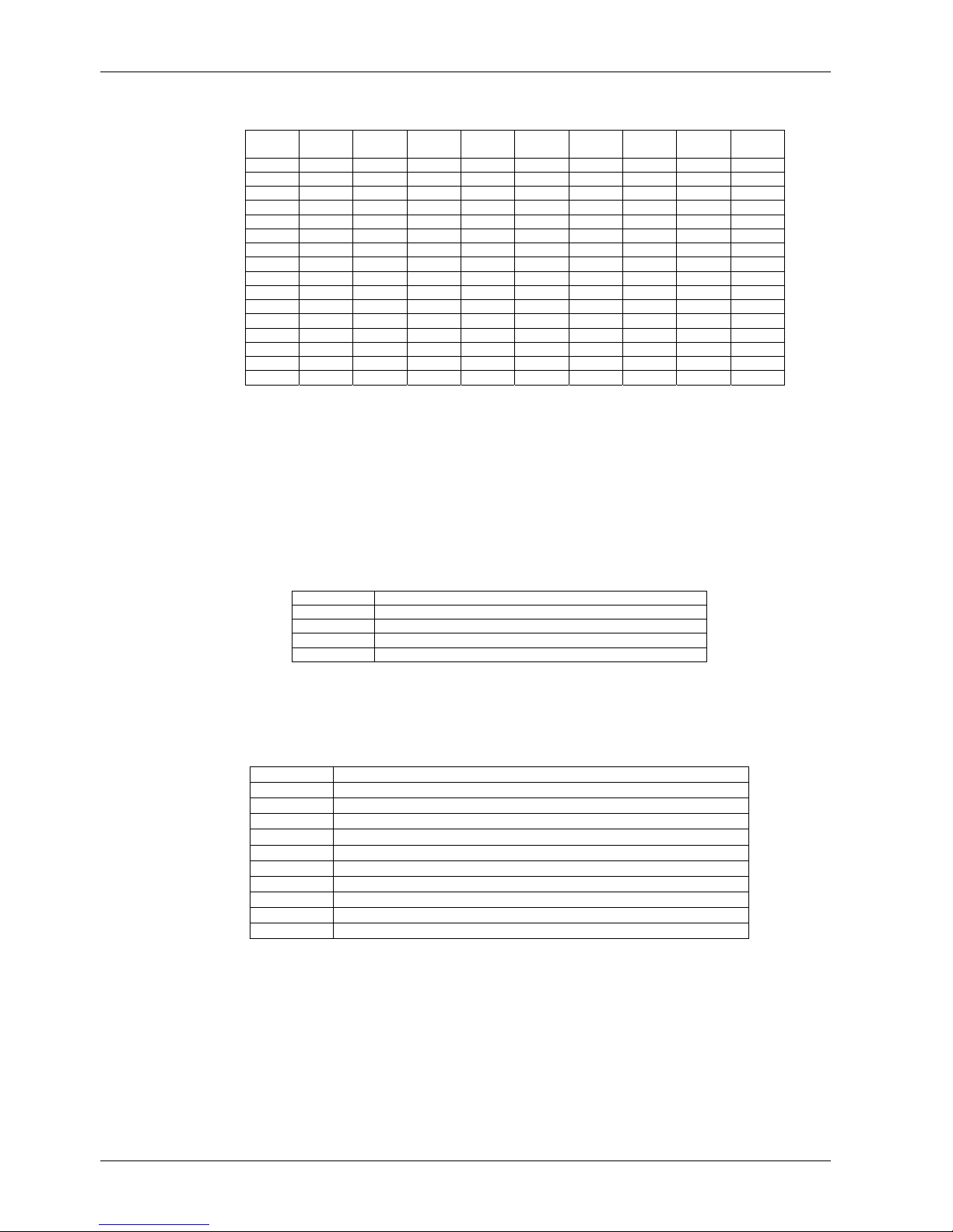
Codepad Indicators
Data
Value
Zone 1
Indicator
0
1 X
2 X
3 X
4 X
5 X
6 X
7 X
8 X
9 X X
10 X
11 X X
12 X X
13 X X
14 X X
15 X X
Zone 2
Indicator
Programming Option Bits
You will notice option bits throughout the quick reference guide. This allows you to program any
combination of the four different options in the one location by adding the options together.
Programming a zero (0) will disable all four options.
Example
If at LOCATION 177 you only want options 1, 2 and 4, add the numbers together and the total is
the number to be programmed. In this example, the number to be programmed is 7 (eg. 1 + 2 + 4
= 7).
Option Description
1
2
4 Answering Machine Bypass Only When Armed
8
Dialler Reporting Functions Allowed
Remote Arming Via Telephone Allowed
Use Bell 103 For FSK Format (Disabled = CCITT V21)
Installer’s Programming Commands
These commands can only be used when you enter Installer’s Programming Mode. Enter the
command followed by the # key.
Command Description
958
959
960 Exit Installer’s Programming Mode
961
962 Copy Panel Memory To Programming Key
963
964 Erase Programming Key
965
966
999
Enable/Disable Zone Status (Hand Held Programmer Required)
Test Programming Ke y
Default System Back To Factory Settings
Copy Programming Key To Panel Me mo ry
Default System For Domestic Dialling Format
Enable/Disable Automatic Stepping Of Locations When Programming
Display Software Version (Hand Held Programmer Required)
Zone 3
Indicator
Solution Ultima 862
Zone 4
Indicator
Zone 5
Indicator
Zone 6
Indicator
Zone 7
Indicator
Quick Reference Guide
Zone 8
Indicator
MAINS
Indicator
SOL ULTIMA 862 QUICK REF GUIDE.DOCBosch Security Systems Pty Limited

Solution Ultima 862
Quick Reference Guide 5
Arming The System (On)
AWAY Mode
1. Pres
2. Enter your code followed by the # key.
TAY Mo
S
1.
2.
S
TAY Mo
1. Pres
s and hold the # key until two beeps are
heard.
Or
[eg. 2580 + #].
de 1
Press and hold the * key until tw
heard.
Or
Enter your code followed by the * key.
eg. 2580 + *].
[
de 2
s and hold the 0 key until two beeps are
heard.
o beeps are
Isolating Zones
Standard Isolating
P
1.
2. Enter the zone number that you want to
3. Press the # k
Code To Isolate
1.
2. Enter your user code
3. Enter the zone number that you want to
4. P
ress the * key twice.
isolate fol
Repeat step 2 if more than one zone is
required to be isolated.
ress the * key o
P
isolate fol
Repeat step 2 if more than one zone is
required to be isolated.
ress the # key to exit when finished.
lowed by the * key.
ey to exit when finished.
nce.
, followed by the
lowed by the * key.
* key .
Disarming The System (Off)
AWAY Mode
Enter your code followed by the # key.
1.
[eg. 2580 + #].
S
TAY Mo
1. Press and hold the * key until tw
2. Enter your code followed by the # key.
TAY Mo
S
1. Pres
2. Enter your code followed by the # key.
de 1
o beeps are
heard (Only if no alarm).
Or
[eg. 2580 + #].
de 2
s and hold the 0 key until two beeps are
heard (Only if no alarm).
Or
[eg. 2580 + #].
Add/Delete RF Devices (Wireless Zones)
Add RF Device
Enter the Installer Code followed by 0 and the
1.
# key [eg. 1234 + 0 + #].
Enter the Device Number (1 – 16) that you
2.
want to add followed by the # key.
Enter the 9-digit RF device ID number
3.
followed by the # key.
Delete RF Device
1. Enter the Installer Code followed by 0 and the
# key [eg. 1234 + 0 + #].
2. Enter the Device Number (1 – 16) that you
want to delete followed by the # key.
3. Press the * key to delete the RF d
evice.
Electronics Design and Manufacturing Pty LimitedSOL ULTIMA 862 QUICK REF GUIDE.D

6
Set First Test Report
1. Enter the Installer Code followed by 1 and the
key [eg. 1234 + 1 + #].
2. Enter the Number Of Days (0 – 15) to wait
until first test report followed by the # key.
Event Memory Recall
1. Enter the Installer Code or Master Code
followed by 8 and the # key.
[eg. 1234 + 8 + #].
The last 40 events (non partitioned) or last 10 events
(partitioned) will be displayed in reverse order (i.e.
most recent to least recent).
Walk Test Mode
Enter the Installer Code or Master Code
1.
followed by 7 and the # key.
[eg. 1234 + 7 + #].
Test each zone as required.
2.
3. Press the # key to exit.
Satellite Siren Service Mode
Enter the Installer Code followed by 5 and the
1.
# key [eg. 1234 + 5 + #].
Telephone Monitor Mode (Toggle On/Off)
Enter the Installer Code followed by 6 and the
1.
# key [eg. 1234 + 6 + #].
2. Press and hold the 9 key until two beeps are
heard to send a test report.
Zone LED Dialling Event
1
2 Dialling Telephone Number
3
4 Data Being Sent
5
None Released Telephone Line
Telephone Line Seized
Handshake Received
Kiss-Off Received
Add A User Code
1. Enter the Master Code followed by 1 and the
# key [eg. 2580 + 1 + #].
2. Enter the User Number (1 – 8) that you want
to add / change followed by the # key.
Enter the New Code followed by the # key.
3.
Solution Ultima 862
Quick Reference Guide
Add RF Keyfob
1. Enter the Master Code followed by 1 and the
# key [eg. 2580 + 1 + #].
Enter the User Number (9 – 16) that you want
2.
to add follo wed by the # key.
Enter the 9-digit RF keyfob ID number
3.
followed by the # key.
Delete A User Code / RF Keyfob
1. Enter the Master Code followed by 1 and the
# key [eg. 2580 + 1 + #].
2. Enter the User Number (1 – 16) that you want
to delete followed by the # key.
3. Press the * key to delete the user code.
Change Domestic Telephone Numbers
Enter the Installer Code or Master Code
1.
followed by 2 and the # key.
[eg. 1234 + 2 + #].
Enter the digits for the telephone number.
2.
3. If more than one telephone number, press the
* key followed by the 4 key (inserts break
between phone numbers) and repeat Step 2,
else press the # key to exit.
Turn Outputs On/Off
Enter the Master Code followed by 5 and the
1.
# key [eg. 2580 + 5 + #].
2. Enter the Output Number (1 – 3) that you
want to toggle on or off.
3. Press the # key to toggle On or the * key to
toggle Off.
4. Press the # key to exit.
Setting Date and Time
Enter the Master Code followed by 6 and the
1.
# key [eg. 2580 + 6 + #].
2. Enter the day (DD), month (MM) and year
(YY) followed by the hour (HH) and minute
(MM).
3. Press the # key to exit.
Day Alarm – Toggle On/Off
1. Press an d hold the 4 key unti l two beeps are
heard. Day alarm will toggle on or off.
SOL ULTIMA 862 QUICK REF GUIDE.DOCBosch Security Systems Pty Limited

Solution Ultima 862
Quick Reference Guide
STAY Mode 2 Zones - Program
1. Enter the Installer Code or Master Code
followed by 4 and the # key .
[eg. 1234 + 4 + #].
2. Enter the Zone Number that you want the
system to automatically isolate followed by the
* key.
Repeat if more than one zone to be
automatically isolated when armed in STAY
Mode 2.
Press the # key to exit.
3.
Fault Analysis
Press and hold the 5 key until two beeps are
1.
heard.
2. Zone Indicators will display FAULT condition
(see table below).
3. Press # key to exit.
Zone
FAULT Condition
LED
1
System Fault
2
RF Low Battery
3
Zone Tamper
4 Sensor Watch
5
RF Sensor Watch
6 Communication Fail
Press and Hold Button 1
To Determine Fault
1 = Battery Fail
2 = Date/Time
3 = RF Rx Jamming
RF Rx Tamper
RF Rx Comm’s Fail
4 = Horn Speaker Fail
5 = Telephone Line Fail
6 = E2 Fail
7 = Fuse Fail
8 = AC Fail
Press and Hold Button 2
To Determine Fault
Displays Zones (1 – 8) that
registers RF Low Battery
Press and Hold Button 3
To Determine Fault
Displays Zones (1 – 8) that
registers Zone Tamper
Press and Hold Button 4
To Determine Fault
Displays Zones (1 – 8) that
registers Zone Tamper
Press and Hold Button 5
To Determine Fault
Displays Zones (1 – 8) that
registers Zone Tamper
Press and Hold Button 6
To Determine Fault
1 = Receiver 1 Fail (Dialler)
2 = Receiver 2 Fail (Dialler)
Codepad Buzzer Tone
1. Press and hold the 8 key until the desired
2.
Test Report
1. Press an d hold the 9 key unti l two beeps are
Speaker Test
1. Press an d hold the 1 key unti l two beeps are
Bell Test
1.
Strobe Test (Toggle On/Off)
1.
2. Press an d hold the 3 key unti l two beeps are
Telco Arm Sequence (Call Forward On)
1. Enter your Installer Code or Master Code
2. Press 1 followed by the # key.
3.
4. Press the # key to exit.
Telco Disarm Sequence (Call Forward On)
1. Enter your Installer Code or Master Code
2. Press 2 followed by the # key.
3. Enter the Call Forward Off sequence.
4.
7
buzzer tone has been reached.
Press the # key to exit.
heard.
heard. The speaker will sound for two
seconds.
Press and hold the 2 key until t wo beeps are
heard. The piezo will sound for two seconds.
Press and hold the 3 key until three beeps are
heard to turn the strobe on.
heard to turn the strobe off.
followed by 3 and the # key.
[eg. 1234 + 3 + #].
Enter the Call Forward On sequence.
followed by 3 and the # key.
[eg. 1234 + 3 + #].
Press the # key to exit.
Modem Call (Alarm Link)
Press and hold the 6 key until two beeps are
1.
heard.
Latching Outputs (Reset)
1. Press and hold the 7 key until two beeps are
heard.
Electronics Design and Manufacturing Pty LimitedSOL ULTIMA 862 QUICK REF GUIDE.D
 Loading...