

Bosch UHO-HBPS, UHO-HGS, UHO-HBGS, UHO-HPS Installation Manual
UHO Camera Housing
UHO-HBPS | UHO-HBGS | UHO-HGS | UHO-HPS
en Installation Manual


Table of contents
1
Safety 4
1.1 Safety message explanation 4
1.2 Safety precautions 4
1.3 Important safety instructions 5
1.4 FCC and ICES compliance 6
2
Short information 7
3
System overview 8
3.1 Available models 8
4
Planning information 9
4.1 Parts list 9
4.2 Unpacking 10
4.3 Tools required 10
5
Installation 11
5.1 Camera/lens requirements 11
5.2 Housing mounting 12
5.3 Opening the cover 12
5.4 Feed-through cables 13
5.4.1 Feed-through power cables 13
5.4.2 Feed-through wiring through the base 13
5.4.3 Feed-through wiring through the rear 13
5.5 Camera/Lens installation 14
5.5.1 Camera tray mount 14
5.5.2 Mounting the camera/tray in the housing 15
6
Connection 16
6.1 Feed-through power connection 16
6.1.1 Incoming power safety earth connection 16
6.1.2 Incoming power wires 17
6.2 Camera connections 18
6.2.1 Camera video connections 18
6.2.2 Camera power connections 18
6.3 Housings with rear connectors 19
6.3.1 Connection – UHO – Rear housing video connection 19
6.3.2 Connection – UHO – Rear housing power connection 19
6.4 Final assembly 20
6.4.1 Camera operation 20
6.4.2 Closing the housing 20
6.4.3 Positioning sunshield 20
7
Maintenance 21
7.1 Fuse replacement 21
8
Decommissioning 22
UHO Camera Housing Table of Contents | en 3
Bosch Security Systems Installation Manual 2014.10 | 5.0 | F.01U.167.418
Safety
Safety message explanation
Danger!
Indicates a hazardous situation which, if not avoided, will result in death or serious injury.
!
Warning!
Indicates a hazardous situation which, if not avoided, could result in death or serious injury.
!
Caution!
Indicates a hazardous situation which, if not avoided, could result in minor or moderate
injury.
Notice!
Indicates a situation which, if not avoided, could result in damage to the equipment or
environment, or data loss.
Safety precautions
!
Warning!
Hazardous voltage
Use caution when working inside the housing. Hazardous voltage is present in the housing
when connected to the AC supply. Do not touch the power terminals when the unit is
powered.
!
Caution!
Installation should only be performed by qualified service personnel in accordance with the
National Electrical Code (NEC 800 CEC Section 60) or applicable local codes.
!
Caution!
This device must be connected to earth (ground).
Safety (power) ground is indicated by the symbol.
!
Caution!
These units must be properly and securely mounted to a supporting structure capable of
sustaining the unit weight. Use care when selecting mounts or pan/tilts (not supplied) for
installation; the mounting surface and unit's weight should be carefully considered.
!
Caution!
To protect the device, the branch circuit protection must be secured with a maximum fuse
rating of 16A. This must be in accordance with NEC 800 (CEC Section 60).
1
1.1
1.2
4 en | Safety UHO Camera Housing
2014.10 | 5.0 | F.01U.167.418 Installation Manual Bosch Security Systems

Important safety instructions
Read, follow, and retain for future reference all of the following safety instructions. Follow all
warnings before operating the unit.
1. Clean only with a dry cloth. Do not use liquid cleaners or aerosol cleaners.
2. Do not install unit near any heat sources such as radiators, heaters, stoves, or other
equipment (including amplifiers) that produce heat.
3. Never spill liquid of any kind on the unit.
4. Take precautions to protect the unit from power and lightning surges.
5. Adjust only those controls specified in the operating instructions.
6. Operate the unit only from the type of power source indicated on the label.
7. Unless qualified, do not attempt to service a damaged unit yourself. Refer all servicing to
qualified service personnel.
8. Install in accordance with the manufacturer's instructions in accordance with applicable
local codes.
9. Use only attachments/accessories specified by the manufacturer.
Power disconnect - Units have power supplied whenever the power cord is inserted into the
power source. The power cord is the main power disconnect for all units.
All-pole power switch - Incorporate an all-pole power switch, with a contact separation of at
least 3 mm, into the electrical installation of the building. If it is needed to open the housing,
use this all-pole switch as the main disconnect device for switching off the voltage to the unit.
Coax grounding:
– Ground the cable system if connecting an outside cable system to the unit.
– Connect outdoor equipment to the unit's inputs only after this unit has had its grounding
plug connected to a grounded outlet or its ground terminal is properly connected to a
ground source.
– Disconnect the unit's input connectors from outdoor equipment before disconnecting the
grounding plug or grounding terminal.
– Follow proper safety precautions such as grounding for any outdoor device connected to
this unit.
Section 810 of the National Electrical Code, ANSI/NFPA No.70, provides information regarding
proper grounding of the mount and supporting structure, grounding of the coax to a discharge
unit, size of grounding conductors, location of discharge unit, connection to grounding
electrodes, and requirements for the grounding electrode.
1.3
UHO Camera Housing Safety | en 5
Bosch Security Systems Installation Manual 2014.10 | 5.0 | F.01U.167.418

FCC and ICES compliance
FCC & ICES Information
(U.S.A. and Canadian Models Only)
This device complies with part 15 of the FCC Rules. Operation is subject to the following
conditions:
– this device may not cause harmful interference, and
– this device must accept any interference received, including interference that may cause
undesired operation.
NOTE: This equipment has been tested and found to comply with the limits for a Class A
digital device, pursuant to Part 15 of the FCC Rules and ICES-003 of Industry Canada. These
limits are designed to provide reasonable protection against harmful interference when the
equipment is operated in a commercial environment. This equipment generates, uses, and
radiates radio frequency energy and, if not installed and used in accordance with the
instruction manual, may cause harmful interference to radio communications. Operation of
this equipment in a residential area is likely to cause harmful interference, in which case the
user will be required to correct the interference at his expense.
Intentional or unintentional modifications, not expressly approved by the party responsible for
compliance, shall not be made. Any such modifications could void the user's authority to
operate the equipment. If necessary, the user should consult the dealer or an experienced
radio/television technician for corrective action.
The user may find the following booklet, prepared by the Federal Communications
Commission, helpful: How to Identify and Resolve Radio-TV Interference Problems. This
booklet is available from the U.S. Government Printing Office, Washington, DC 20402, Stock
No. 004-000-00345-4.
1.4
6 en | Safety UHO Camera Housing
2014.10 | 5.0 | F.01U.167.418 Installation Manual Bosch Security Systems

Short information
This manual has been compiled with great care and the information it contains has been
thoroughly verified. The text was correct at the time of printing, however, the content can
change without notice. Bosch Security Systems accepts no liability for damage resulting
directly or indirectly from faults, incompleteness or discrepancies between this manual and
the product described.
Trademarks
All hardware and software product names used in this document are likely to be registered
trademarks and must be treated accordingly.
More information
For more information please contact the nearest Bosch Security Systems location or visit
www.boschsecurity.com
2
UHO Camera Housing Short information | en 7
Bosch Security Systems Installation Manual 2014.10 | 5.0 | F.01U.167.418
System overview
Available models
These outdoor camera housings are available in several versions. The variants are input power
supply, fitted connectors and temperature control. All models are equipped with a heater and
a sunshield. The maximum camera/lens size (H x W x D) for all models is 91 x 81 x 262 mm
(3.6 x 3.2 x10.3 in).
– UHO-HBGS and UHO-HBPS models have a blower (fan).
– UHO-HGS and UHO-HBGS models have feed-through holes for power and signal cabling.
– UHO-HPS and UHO-HBPS models have a 4-pin power connector and a BNC connector
instead of feed-through holes.
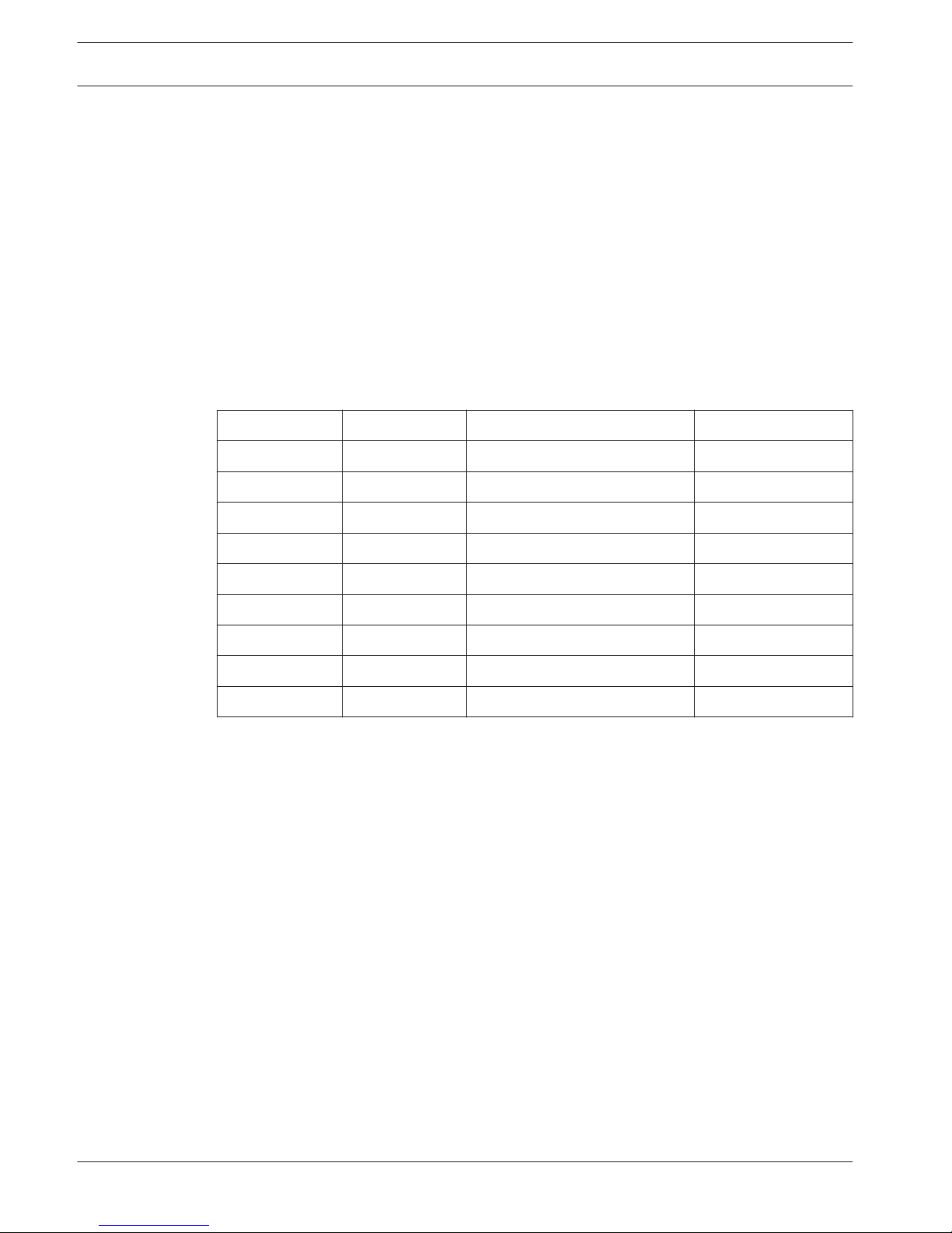
The following models are available:
Model
Input voltage Connection Temperature control
UHO-HBGS-11 24 VAC Feed-through Fan
UHO-HBGS-51 230 VAC Feed-through Fan
UHO-HBGS-61 115 VAC Feed-through Fan
UHO-HGS-11 24 VAC Feed-through Passive
UHO-HGS-51 230 VAC Feed-through Passive
UHO-HBPS-11 24 VAC Power and BNC connectors Fan
UHO-HBPS-51 230 VAC Power and BNC connectors Fan
UHO-HPS-51 230 VAC Power and BNC connectors Passive
All models have an internal +12 VDC power supply available for the camera. Alternatively, the
input voltage is also available to power the camera.
3
3.1
8 en | System overview UHO Camera Housing
2014.10 | 5.0 | F.01U.167.418 Installation Manual Bosch Security Systems
 Loading...