

Page 1
Fire Alarm Systems | SS‑P Two‑wire Indoor Horn Strobes
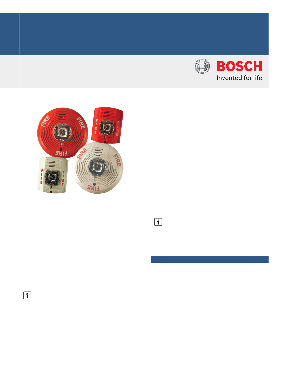
SS‑P Two‑wire Indoor Horn Strobes
www.boschsecurity.com
u Plug‑in design with tamper-resistant construction
u Field‑selectable standard candela (15 cd, 15/75 cd,
30 cd, 75 cd, 95 cd, 110 cd, or 115 cd) settings or
high candela settings (135 cd, 150 cd, 177 cd, or
185 cd)
The SS‑P System Sensor SpectrAlert Advance
notification appliances simplify installations with
features such as plug‑in designs, instant feedback
messages to ensure correct installation of individual
devices, and field‑selectable candela settings. While
there are products specifically designed for use on the
ceiling or the wall, these products are listed to be
used in either application, and the same mounting
plate is used for wall- and ceiling‑mount units.
SpectrAlert products can be used in either DC or
full‑wave rectified (FWR) systems (12 V or 24 V). If
required, the SSMDL or SSMDLW module can be used
to provide synchronization.
Notice
Full‑wave Rectified (FWR) voltage is a
non‑regulated, time‑varying power source that is
used on some power supply and panel outputs.
u Horn rated at 88 dbA or greater at 16 V
u Rotary switch selection for horn tone and one of
three volumes
u Shorting spring on mounting plate for continuity
check before installation
Notice
SpectrAlert products set at 15 cd and 15/75 cd
automatically work on either 12 V or 24 V power
supplies. The products are not listed for 12 V
operating voltages when set to any other candela
settings.
Functions
Horn
The horn has three volume options and an option to
switch between a temporal Code 3 pattern and a
non‑temporal (continuous) pattern. These options are
set by a multiple position switch.
Strobe
When wired as a primary-signaling notification
appliance, the strobe complies with the Americans
with Disabilities Act (ADA) requirements for visible
signaling appliances, flashing at 1 Hz over the strobe's
entire operating voltage range. The strobe light
consists of a xenon flash tube and associated lens and
reflector system.
Page 2
2 | SS‑P Two‑wire Indoor Horn Strobes
For 24 V applications, the total number of strobes on a
single NAC must not exceed 40, with a maximum loop
resistance of 120 Ω. For 12 V applications, the total
number of strobes must not exceed 12, with a
maximum loop resistance of 30 Ω.
Certifications and approvals
System Sensor holds these Listings and Approvals:
Region Certification
USA UL ULSZ: Audible Signal Appliances
(UL464)
FM SS-P Family
CSFM see our website
Installation/configuration notes
Mounting Considerations
These horn strobes mount on a standard 4‑inch square
back box, a 4‑inch octagon back box, a single‑gang
back box, or a double‑gang back box.
Wiring Considerations
The input terminals on the universal mounting plate
accept solid wires between 12 AWG (2.3 mm) to
18 AWG (1.2 mm).
15/75 cd - Temporal Code 3 Pattern
DC FWR
High dB Setting: 147 mA 155 mA RMS
Medium dB Setting: 144 mA 152 mA RMS
Low dB Setting: 143 mA 151 mA RMS
15/75 cd – Non‑temporal (continuous) Pattern
DC FWR
High dB Setting: 152 mA 161 mA RMS
Medium dB Setting: 145 mA 155 mA RMS
Low dB Setting: 144 mA 154 mA RMS
Current Draw, UL maximum at 16 V to 33 V
Standard-candela Models
15 cd - Temporal Code 3 Pattern
DC FWR
High dB Setting: 79 mA 88 mA RMS
Medium dB Setting: 69 mA 78 mA RMS
Low dB Setting: 66 mA 76 mA RMS
Parts included
Quant. Component
1 Horn strobe
1 Universal mounting plate (MP120K)
1 Hardware pack
1 Literature pack
Technical specifications
Electrical
Current Draw, UL maximum at 8 V to 17.5 V
Standard-candela Models only
15 cd - Temporal Code 3 Pattern
DC FWR
High dB Setting: 137 mA 136 mA RMS
Medium dB Setting: 132 mA 129 mA RMS
Low dB Setting: 132 mA 129 mA RMS
15 cd – Non‑temporal (continuous) Pattern
DC FWR
High dB Setting: 141 mA 142 mA RMS
Medium dB Setting: 133 mA 134 mA RMS
Low dB Setting: 131 mA 132 mA RMS
15 cd – Non‑temporal (continuous) Pattern
DC FWR
High dB Setting: 91 mA 103 mA RMS
Medium dB Setting: 75 mA 85 mA RMS
Low dB Setting: 68 mA 80 mA RMS
15/75 cd - Temporal Code 3 Pattern
DC FWR
High dB Setting: 90 mA 97 mA RMS
Medium dB Setting: 80 mA 88 mA RMS
Low dB Setting: 77 mA 86 mA RMS
15/75 cd – Non‑temporal (continuous) Pattern
DC FWR
High dB Setting: 100 mA 112 mA RMS
Medium dB Setting: 85 mA 95 mA RMS
Low dB Setting: 79 mA 90 mA RMS
30 cd - Temporal Code 3 Pattern
DC FWR
High dB Setting: 107 mA 112 mA RMS
Medium dB Setting: 97 mA 103 mA RMS
Low dB Setting: 93 mA 101 mA RMS
30 cd – Non‑temporal (continuous) Pattern
Page 3

3 | SS‑P Two‑wire Indoor Horn Strobes
DC FWR
High dB Setting: 116 mA 126 mA RMS
Medium dB Setting: 102 mA 110 mA RMS
Low dB Setting: 96 mA 105 mA RMS
75 cd - Temporal Code 3 Pattern
DC FWR
High dB Setting: 176 mA 168 mA RMS
Medium dB Setting: 157 mA 160 mA RMS
Low dB Setting: 154 mA 160 mA RMS
75 cd – Non‑temporal (continuous) Pattern
DC FWR
High dB Setting: 176 mA 181 mA RMS
Medium dB Setting: 163 mA 166 mA RMS
Low dB Setting: 156 mA 161 mA RMS
95 cd - Temporal Code 3 Pattern
DC FWR
High dB Setting: 194 mA 190 mA RMS
Medium dB Setting: 182 mA 184 mA RMS
Low dB Setting: 179 mA 184 mA RMS
95 cd – Non‑temporal (continuous) Pattern
DC FWR
High dB Setting: 201 mA 203 mA RMS
Medium dB Setting: 187 mA 189 mA RMS
Low dB Setting: 182 mA 184 mA RMS
110 cd - Temporal Code 3 Pattern
DC FWR
High dB Setting: 212 mA 210 mA RMS
Medium dB Setting: 201 mA 202 mA RMS
Low dB Setting: 198 mA 194 mA RMS
110 cd – Non‑temporal (continuous) Pattern
DC FWR
High dB Setting: 221 mA 221 mA RMS
Medium dB Setting: 207 mA 208 mA RMS
Low dB Setting: 201 mA 202 mA RMS
115 cd - Temporal Code 3 Pattern
DC FWR
High dB Setting: 218 mA 218 mA RMS
Medium dB Setting: 210 mA 206 mA RMS
Low dB Setting: 207 mA 201 mA RMS
115 cd – Non‑temporal (continuous) Pattern
DC FWR
High dB Setting: 229 mA 229 mA RMS
Medium dB Setting: 216 mA 216 mA RMS
Low dB Setting: 210 mA 211 mA RMS
Current Draw, UL maximum at 16 V to 33 V
High-candela Models
135 cd - Temporal Code 3 Pattern
DC FWR
High dB Setting: 245 mA 215 mA RMS
Medium dB Setting: 235 mA 209 mA RMS
Low dB Setting: 232 mA 207 mA RMS
135 cd – Non‑temporal (continuous) Pattern
DC FWR
High dB Setting: 255 mA 233 mA RMS
Medium dB Setting: 242 mA 219 mA RMS
Low dB Setting: 238 mA 214 mA RMS
150 cd - Temporal Code 3 Pattern
DC FWR
High dB Setting: 259 mA 231 mA RMS
Medium dB Setting: 253 mA 224 mA RMS
Low dB Setting: 251 mA 221 mA RMS
150 cd – Non‑temporal (continuous) Pattern
DC FWR
High dB Setting: 270 mA 248 mA RMS
Medium dB Setting: 259 mA 232 mA RMS
Low dB Setting: 254 mA 229 mA RMS
177 cd - Temporal Code 3 Pattern
DC FWR
High dB Setting: 290 mA 258 mA RMS
Medium dB Setting: 288 mA 250 mA RMS
Low dB Setting: 282 mA 248 mA RMS
177 cd – Non‑temporal (continuous) Pattern
DC FWR
High dB Setting: 303 mA 275 mA RMS
Medium dB Setting: 293 mA 262 mA RMS
Low dB Setting: 291 mA 256 mA RMS
Page 4

4 | SS‑P Two‑wire Indoor Horn Strobes
185 cd - Temporal Code 3 Pattern
DC FWR
High dB Setting: 297 mA 265 mA RMS
Medium dB Setting: 297 mA 258 mA RMS
Low dB Setting: 292 mA 256 mA RMS
185 cd – Non‑temporal (continuous) Pattern
DC FWR
High dB Setting: 309 mA 281 mA RMS
Medium dB Setting: 299 mA 267 mA RMS
Low dB Setting: 295 mA 262 mA RMS
Voltage
Nominal: Regulated 12 VDC/FWR or
Operating Range: 12V nominal: 8 V to 17.5 V or
Regulated 24 VDC/FWR
24 V nominal: 16 V to 33 V
Environmental
Relative Humidity: 10% to 93%, non‑condensing
Temperature (operating): +32°F to +120°F (0°C to +49°C)
Mechanical
Dimensions
• Ceiling-mount
(Diameter x Height):
6.8 in × 2.5 in (173 mm × 64 mm)
High dB Setting: 82 dBA 88 dBA
Medium dB Setting: 78 dBA 85 dBA
Low dB Setting: 75 dBA 81 dBA
Trademarks
All hardware and software product names used in this
document are likely to be registered trademarks and
must be treated accordingly.
Ordering information
SS‑P2R Wall‑mount, Standard‑candela Horn Strobe (red)
Red, wall‑mount device with field‑selectable strobe
intensities of 15 cd, 15/75 cd, 30 cd, 75 cd, 95 cd,
110 cd, or 115 cd and rotary switch selection for horn
tone and one of three volumes
Order number SS-P2R
SS‑P2W Wall‑mount, Standard‑candela Horn Strobe
(white)
White, wall‑mount device with field‑selectable strobe
intensities of 15 cd, 15/75 cd, 30 cd, 75 cd, 95 cd,
110 cd, or 115 cd and rotary switch selection for horn
tone and one of three volumes
Order number SS-P2W
SS‑PC2R Ceiling‑mount, Standard‑candela Horn Strobe
(red)
Red, ceiling‑mount device with field‑selectable strobe
intensities of 15 cd, 15/75 cd, 30 cd, 75 cd, 95 cd,
110 cd, or 115 cd and rotary switch selection for horn
tone and one of three volumes
Order number SS-PC2R
• Wall-mount (Height x
Width x Depth):
Candela Selections: 15 cd1, 15/75 cd1, 30 cd2, 75 cd2,
1
When set at these settings, the devices automatically
5.6 in × 4.7 in × 2.5 in
(142 mm × 119 mm × 64 mm)
95 cd2, 110 cd2, and 115 cd
2
work on both 12 V and 24 V power supplies. The
15/75 cd selection is listed at 15 cd but provides
75 cd on axis.
2
The strobe is not listed for 12 V operating voltages
when set to these selections. When using a 12 V
control panel, this device yields required light output
only in the 15 cd and 15/75 cd settings.
Horn Audibility (minimum) for DC or FWR
Temporal Code 3 Pattern
8 V to 17.5 V 16 V to 33 V
High dB Setting: 78 dBA 84 dBA
Medium dB Setting: 74 dBA 80 dBA
Low dB Setting: 71 dBA 76 dBA
Non‑temporal (continuous) Pattern
8 V to 17.5 V 16 V to 33 V
SS‑PC2W Ceiling‑mount, Standard‑candela Horn Strobe
(white)
White, ceiling‑mount device with field‑selectable
strobe intensities of 15 cd, 15/75 cd, 30 cd, 75 cd, 95
cd, 110 cd, or 115 cd and rotary switch selection for
horn tone and one of three volumes
Order number SS-PC2W
SS‑PC2RH Ceiling‑mount, High‑candela Horn Strobe
(red)
Red, ceiling‑mount device with field‑selectable strobe
intensities of 135 cd, 150 cd, 177 cd, or 185 cd and
rotary switch selection for horn tone and one of three
volumes
Order number SS-PC2RH
SS‑PC2WH Ceiling‑mount, High‑candela Horn Strobe
(white)
White, ceiling‑mount device with field‑selectable
strobe intensities of 135 cd, 150 cd, 177 cd, or 185 cd
and rotary switch selection for horn tone and one of
three volumes
Order number SS-PC2WH
Page 5

5 | SS‑P Two‑wire Indoor Horn Strobes
Represented by:
Americas: Europe, Middle East, Africa: Asia-Pacific: China: America Latina:
Bosch Security Systems, Inc.
130 Perinton Parkway
Fairport, New York, 14450, USA
Phone: +1 800 289 0096
Fax: +1 585 223 9180
security.sales@us.bosch.com
www.boschsecurity.us
Bosch Security Systems B.V.
P.O. Box 80002
5617 BA Eindhoven, The Netherlands
Phone: + 31 40 2577 284
Fax: +31 40 2577 330
emea.securitysystems@bosch.com
www.boschsecurity.com
Robert Bosch (SEA) Pte Ltd, Security
Systems
11 Bishan Street 21
Singapore 573943
Phone: +65 6571 2808
Fax: +65 6571 2699
apr.securitysystems@bosch.com
www.boschsecurity.asia
Bosch (Shanghai) Security Systems Ltd.
201 Building, No. 333 Fuquan Road
North IBP
Changning District, Shanghai
200335 China
Phone +86 21 22181111
Fax: +86 21 22182398
www.boschsecurity.com.cn
Robert Bosch Ltda Security Systems Division
Via Anhanguera, Km 98
CEP 13065-900
Campinas, Sao Paulo, Brazil
Phone: +55 19 2103 2860
Fax: +55 19 2103 2862
latam.boschsecurity@bosch.com
www.boschsecurity.com
© Bosch Security Systems 2014 | Data subject to change without notice
2722182795 | en, V2, 02. Sep 2014
Accessories
SS‑BBS‑2 Wall Back Box Skirt (red)
Red back box skirt.
Not Available.
Order number SS-BBS-2
SS‑BBSW‑2 Wall Back Box Skirt (white)
White back box skirt
Order number SS-BBSW-2
SS‑BBSC‑2 Ceiling Back Box Skirt (red)
Red back box skirt.
Not Available.
Order number SS-BBSC-2
SS‑BBSCW‑2 Ceiling Back Box Skirt (white)
White back box skirt.
Not Available.
Order number SS-BBSCW-2
SSMDL Synchronization Module (red)
Red, 24VDC device that can connect to two Style Y
(Class B) circuits or one Style Z (Class A) circuit and
synchronize System Sensor SpectrAlert horns, strobes,
and horn strobes.
Not Available.
Order number SSMDL
SSMDLW Synchronization Module (white)
White, 24VDC device that can connect to two Style Y
(Class B) circuits or one Style Z (Class A) circuit and
synchronize System Sensor SpectrAlert horns, strobes,
and horn strobes.
Not Available.
Order number SSMDLW
 Loading...